Tutorials
- (MAC) How to use Phomemo Thermal Printer M834
- (MAC) Automatic printing with Automator
- How to hack a brainwave EEG toy - Force Trainer II
- Connecting a Potentiometer
- Controlling an actuator with a N-channel Mosfet
- Controlling an actuator with TinkerKit Mosfet
- DFRobot Sensor Testing: HX711 Weight Sensor, Voice Recorder Module Pro, Speech Synthesis Module V2
- How to build a Simple Robot Arm with Servo Motor and Joystick
- How to connect a Light Dependent Resistor (LDR)
- How to connect a push button or switch
- How to control Arduino without using delay()
- How to control Arduino without using delay()
- How to install libraries
- How to make Animation on NeoMatrix
- How to make Animation on NeoMatrix with Processing
- How to Program an ATtiny85 with an Arduino Uno
- How to send data to p5.js from Arduino
- How to send data to Processing from Arduino
- How to use a Bare Conductive Touch Board with Arduino
- How to use a Hall Effect Sensor
- How to use a Neopixel strip
- How to use a PIR sensor
- How to use a relay module
- How to use a rotary encoder
- How to use DFPlayer mini to play MP3
- How to use Grove Serial Bluetooth v3.0
- How to use MatrixPortal M4
- Touch sensor - with No Sensor!
- Making Breathing Light with LEDs
- Making sounds with a piezo
- Powering an Arduino
- Making a Force Sensor/ a Button with Velostat & Conductive Fabric
- Using a Force Sensor
- Using a Membrane Potentiometer (SoftPot)
- Using a HC-SR04 distance sensor
- Using a Monochrome 1.3" 128x64 OLED display
- Using a Soil Moisture Sensor
- Using a Sparkfun MP3 Trigger
- Using a Sparkfun Sound Detector
- Using a TCS34725 RGB Color Sensor
- Using a Vibration Motor
- Using an MFRC522 RFID reader
- Touch sensor - Using an MPR121
- Touch sensor - Using an CAP1188
- Using an PN532 RFID reader
- Using Arduino Leonardo to send USB MIDI data
- Using AVR ISP MKII to upload firmware to Arduino
- Using L293D IC for motors
- Using MatrixPortal M4 for animation
- Using the MAX9814 mic amplifier
- Using the serial monitor and serial logger
- Using Smartphont to Read NFC tag
- Using NFC Tools to Read/Write NFC tag
(MAC) How to use Phomemo Thermal Printer M834
What is Phomemo Thermal Printer M834?
Phomemo M834 thermal portable printer that can print black and white text and graphics inklessly on different sizes 216mm/210mm/110mm/80mm/53mm (US Letter/A4/4.33"/3.14"/2.08") of thermal papers.
1. Install Printer Driver
Please visit the official site to download the driver and install the driver according to the guide.
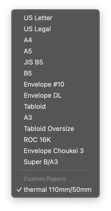
2. Create Custom paper size
If you are using thermal paper that is not the standard A4 or US Letter size, then you will need to create a custom paper size for your thermal paper.
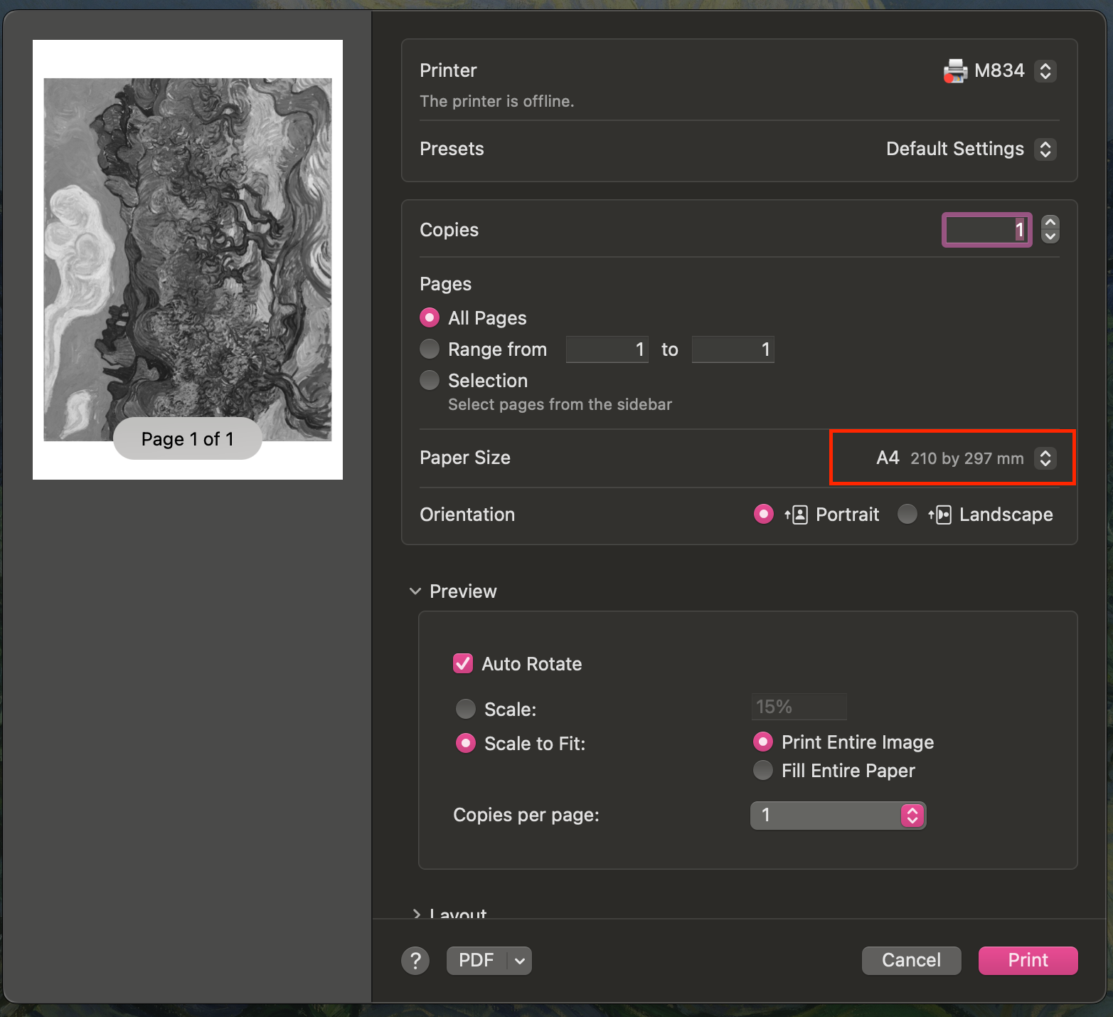
- Open any files or images, eg. Preview, the click
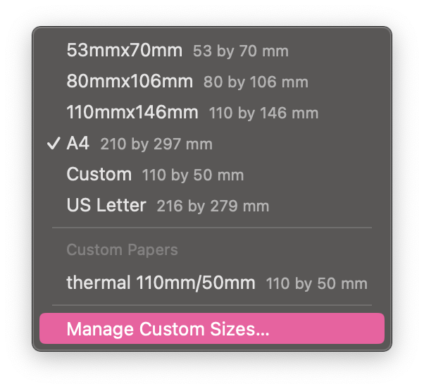
File->Print - Click the drop down menu of Paper Size

- Click Manage Custom Sizes

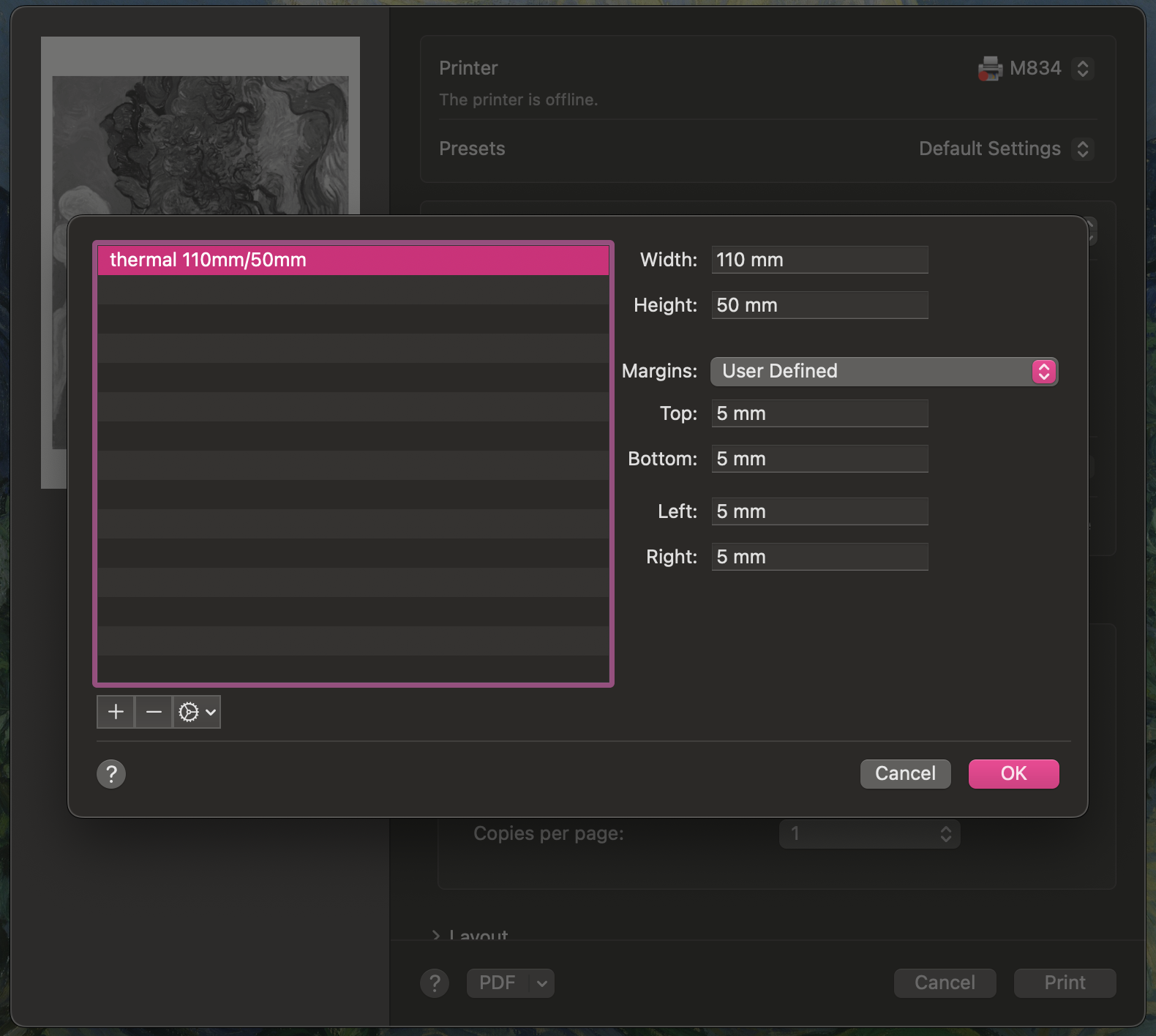
- Use the
+button to create a size for your paper. For example in this screenshot, I am using a thermal paper roll of 110mm wide. The height, however, should be based on the height of your graphics/ files, as it is a roll which means the height can be indefinite for the printer. I set the height as 50mm, as my intended printing file is going to be 50mm tall. At last, remember at least 3mm margins.
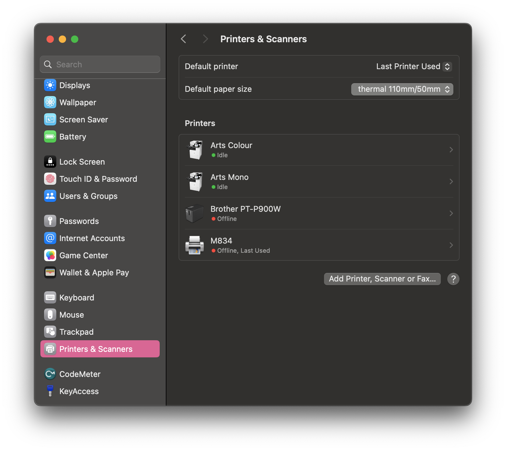
3. Set Default Paper size
You will need to set your new custom paper size as the default paper size before you print. Although you can select the paper size everytime you print instead, it is essential if you want to do auto-printing in the next step.
- Go to
System Settings->Printers & Scanners - Click the drop down menu of Default paper size

- Select your new custom paper size

4. Set up Auto-Printing with Automator
We have a tutorial for setting up automatic printing with Automator on MAC here.
(MAC) Automatic printing with Automator
What is Automator?
Apple’s Automator is a built-in Mac feature that allows users to easily “program” their Macs to automatically execute certain repetitive tasks, thus saving time by removing the need to perform said tasks manually.
Automator can be helpful when you don't have much programming knowledge or don't want to do a lot of coding. One of the most common usage is Auto-printing. Unfortunately, the app is not available for other operating systems.
1. Launch Automator
Search for "Automator" in Spotlight and launch.

2. Folder Action
You will see this dialogue when you launch Automator and choose Folder Action.

3. Print Finder Items
Drag Print Finder Items to the right side of the window.

4. Choose Folder & Printer
Choose the folder where you want to put all your printing files and choose the printer that you want to use as the default printer.

5. Save the Script

6. Quit Automator
You must quit the Automator for it to work.

7. Testing
Put some files into the folder you chose above.

8. Printing
All files should be sent and lined up in the Printer dialogue.

Now that you have set up a auto-print workflow, it can be a great add-on for your project. For example, we have a generative graphic sketch in Processing, we program it to save the graphics every 1 minute in a designated folder and the Automator will print it auotmatically through a thermal printer.
How to hack a brainwave EEG toy - Force Trainer II
What is a NeuroSky Brainwave?
NeuroSky Brainwave is a technology that uses EEG (Electroencephalography) sensors to detect electrical activity in the brain. The NeuroSky chip processes these brain signals and translates them into digital data, which can be used in applications like gaming, meditation tracking, and brain-computer interfaces (BCIs).
Although the actual headset is quite pricey, the NeuroSky chip can be found on brainwave-controlled toys such as the Star Wars Force Trainer. The toy can be hacked with a arduino. This tutorial is based on JimRosKind's tutorial.

Wiring
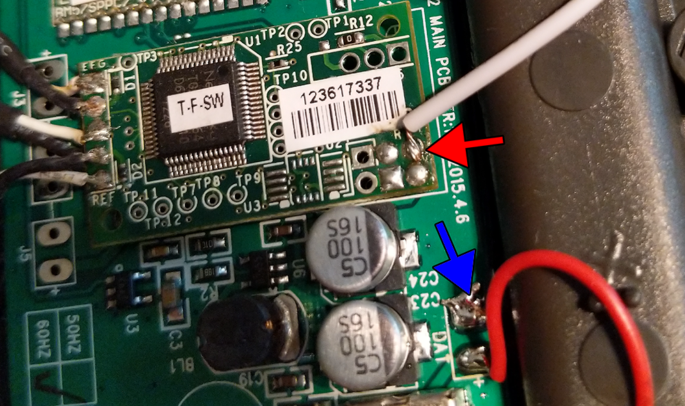
In this tutorial, we are using an UNO, hardware Serial (pins 0 & 1) is shared with the USB connection, therefore we need to use software serial to communicate with the NeuroSky chip.
- Solder a wire from the T pin (red arrow) (red circle & white wire) on the chip and connect that wire to pin 2 on Arduino
- Solder a wire from the - (blue arrow) on the chip next to the battery and connect that wire to GND on Arduino.
Getting started
The following is a sketch that will print out the signal quality, attention and meditation data.
#include <SoftwareSerial.h>
// Define the RX/TX pins for SoftwareSerial
SoftwareSerial mindwaveSerial(2, 3); // RX, TX
void setup() {
Serial.begin(57600); // Serial monitor baud rate
mindwaveSerial.begin(57600); // NeuroSky baud rate
}
void loop() {
readMindwave();
}
void readMindwave() {
static int state = 0;
static byte payload[256];
static int payloadLength = 0, payloadIndex = 0;
static byte checksum = 0;
while (mindwaveSerial.available()) {
byte byteRead = mindwaveSerial.read();
switch (state) {
case 0: // Waiting for first sync byte (0xAA)
if (byteRead == 0xAA) state = 1;
break;
case 1: // Waiting for second sync byte (0xAA)
if (byteRead == 0xAA) state = 2;
else state = 0;
break;
case 2: // Read payload length
if (byteRead > 169) { // Invalid length, reset
state = 0;
} else {
payloadLength = byteRead;
payloadIndex = 0;
checksum = 0;
state = 3;
}
break;
case 3: // Read payload
payload[payloadIndex++] = byteRead;
checksum += byteRead;
if (payloadIndex == payloadLength) state = 4;
break;
case 4: // Verify checksum
checksum = ~checksum & 0xFF; // Compute checksum
if (checksum == byteRead) {
processPayload(payload, payloadLength);
}
state = 0;
break;
}
}
}
void processPayload(byte *payload, int length) {
for (int i = 0; i < length; i++) {
byte code = payload[i];
if (code == 0x02) { // Signal Quality
int signalQuality = payload[++i];
Serial.print("Signal Quality: ");
Serial.println(signalQuality);
}
else if (code == 0x04) { // Attention
int attention = payload[++i];
Serial.print("Attention: ");
Serial.println(attention);
}
else if (code == 0x05) { // Meditation
int meditation = payload[++i];
Serial.print("Meditation: ");
Serial.println(meditation);
}
}
}
Connecting a Potentiometer
What is a potentiometer?
A potentiometer (often abbreviated to pot) is an electronic component with three connections, the main purpose of the pot is to create a variable voltage as an input to a circuit, for example controlling how loud your speakers should be.

Inside a potentiometer is a large resistive area between pin #1 and #3, the middle pin #2 is called the wiper, and by actuating the pot you can select a position along that resistive area to create a proportional to the voltage between pins #1 and #3.
For example if you have Ground (0V) on pin #1, and 5V on pin #3, you could select a voltage between 0V to 5V, at the half way the voltage on pin #2 would be 2.5V.
Different types
There are two main types:

Rotary Potentiometers like those found on speakers to control the volume.

Slide Potentiometer like those found on audio mixing desks.
Wiring
At its most basic, pins #1 and #3 need to be connected to Power and Ground, for example 5V and GND on an Arduino. Pin #2 the wiper needs to be connected to the analog input pins (eg. A0-A5 for Arduino UNO).
Rotary Potentiometer Wiring

Slide Potentiometer Wiring

Identifying the pins of a potentiometer
The most common type of potentiometer to use is a 10KΩ potentiometer, that means the resistance between pin #1 and #3 is fixed at 10KΩ or thereabouts, and that the resistance between pin #2 and either of the other two will be proportional to the position of the potentiometer rotation/sliding.
In other words, using a multimeter set to resistance/ohms/Ω measurement you can find the two pins that don't change at all, and measure a resistance close to the rating marked on it. The remaining leg is likely the wiper.
Getting started
The following is a simple sketch that will get a potentiometer controlling the LED built into the Arduino.
This sketch will make the LED blink at a rate between 0ms to 1023ms, this is because the function analogRead returns a value between 0-1023.
#define ledPin 13
#define potPin A0
void setup() {
pinMode( ledPin, OUTPUT );
pinMode( potPin, INPUT );
}
void loop() {
digitalWrite( ledPin, HIGH );
delay( analogRead( potPin ) );
digitalWrite( ledPin, LOW );
delay( analogRead( potPin ) );
}
Controlling an actuator with a N-channel Mosfet
What is Mosfet?
A MOSFET (Metal-Oxide-Semiconductor Field-Effect Transistor) is a type of transistor used to switch or amplify electrical signals in electronic devices. It’s one of the most common components in electronic circuits, especially in digital and analog systems.
Structure
A MOSFET has three main terminals — Gate, Drain, and Source. The Gate is separated from the channel by a thin insulating layer of silicon dioxide (SiO₂).
Operation
A small voltage applied to the Gate controls the current flow between the Drain and Source terminals. By adjusting this voltage, the MOSFET can act as a switch (turning the current on or off) or as an amplifier (controlling the level of current flow).
Types
There are two main types of MOSFETs, we will be using a N-channel Mosfet in this tutorial.e
- N-channel MOSFETs: These conduct when a positive voltage is applied to the Gate relative to the Source.
- P-channel MOSFETs: These conduct when a negative voltage is applied to the Gate relative to the Source.
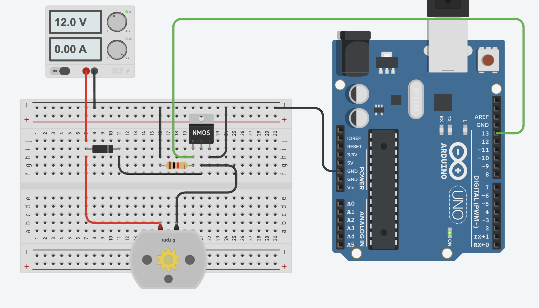
Wiring
- Source (S) to
GND - Drain (D) to
actuator(-)& todiode(-) - Gate (G) to
GNDvia 1k resistor & toPin 13 - Power Supply(+) to
actuator(+)&diode(+) - Power Supply(-) to
GND
Basic Example
This basic example is effectively the blink sketch, the TinkerKit Mosfet operates just like any other digital device.
#define actuatorPin 13
void setup() {
pinMode( actuatorPin, OUTPUT );
}
void loop() {
digitalWrite( actuatorPin, HIGH );
delay( 1000 );
digitalWrite( actuatorPin, LOW );
delay( 1000 );
}
Controlling an actuator with TinkerKit Mosfet
What is the TinkerKit Mosfet?
The TinkerKit Mosfet is a simple module for controlling devices like motors, solenoids, LED strips and electromagnets which require higher voltages and currents than the Arduino can handle alone.
Typically you might find an example of a mosfet circuit online when trying to solve this problem, however high current circuits can melt breadboards, and accidentally wiring up the 12 or 24 volt power supply to your Arduino is a easily made mistake that will damage the Arduino and potentially your computer.
For this reason we use a small, cheap module which takes away all these headaches, on the Arduino side you have three header pins and on the actuator side you've got your power in, and switched power out.
In effect TinkerKit Mosfet is an electronic switch that can turn your actuator on and off using an Arduino.
Wiring
There are three wires to connect on the Arduino side:
- Ground (
-connects toGND) - Power (
+connects to5V) - Signal (The middle pin connects to your Arduino pin e.g. pin 6)
On the other side there are four screw terminals, labeled:
- GND (Connects to your power supply ground)
- +V (Connects to your power supply positive)
- M+ (Connects to one side of your actuator)
- M- (Connects to the other side of your actuator)
**Warning**
The TinkerKit Mosfet can only drive up to 24V DC.

Getting started
After wiring up the board it can be controlled via digitalWrite just like an LED. There are some quick examples below:
Basic Example
This basic example is effectively the blink sketch, the TinkerKit Mosfet operates just like any other digital device.
#define actuatorPin 6
void setup() {
pinMode( actuatorPin, OUTPUT );
}
void loop() {
digitalWrite( actuatorPin, HIGH );
delay( 1000 );
digitalWrite( actuatorPin, LOW );
delay( 1000 );
}
Advanced Example
You can also control the speed of some actuators, normally this is only useful for motors, this is accomplished using analogWrite (PWM) this is effectively the same as setting the brightness of an LED.
**Danger**
Below a certain voltage/PWM value most actuators such as motors will stall (won't turn), this will cause the motor to become extremely hot potentially causing a fire damaging the motor, or burning you.
Always make sure your code prevents the speed of the motor going below the stall speed,
you can find the stall speed by testing different values until the motor is only just turning, this should be your minimum.
#define actuatorPin 6
void setup() {
pinMode( actuatorPin, OUTPUT );
}
void loop() {
// This example uses 128 as an example of the minimum motor speed to protect the motor
for ( int i = 128; i < 255; i++ ) {
analogWrite( actuatorPin, i );
delay( 10 );
}
}
DFRobot Sensor Testing: HX711 Weight Sensor, Voice Recorder Module Pro, Speech Synthesis Module V2
We tested a few DFRobot sensors by following their tutorials. Before you jump into using these sensors, we have some tips for you.
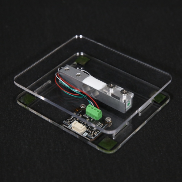
HX711 Weight Sensor
This sensor can measure weight up to 1kg, and is compatible with Arduino, micro:bit, ESP32 and Raspberry Pi via I2C communication.
You will need to install the library DFRobot_HX711_I2C library which is available in Arduino library manager. However, the Arduino source file DFRobot_HX711_I2C.h will prompt an error in the console. To fix it, you simply need to remove this part sensor IIC address*/ from this line #define HX711_I2C_ADDR (0x64) sensor IIC address*/.
Please see here for their official tutorial.
Speech Synthesis Module V2
This module can turn text into speech. It supports both English and Mandarin languages and uses I2C or UART for communication.
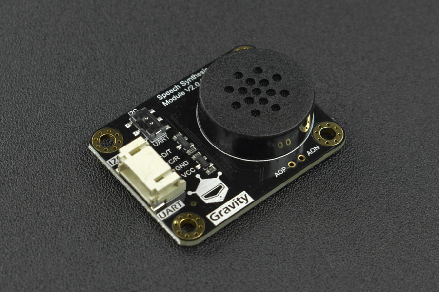
If you are using the V2 version, make sure you download and install the DFRobot_SpeechSynthesis_V2 library which is only available via manual install. There is a tutorial for installing libraries on Arduino.
In the V2 library, you can only use the Female voice, but you can change the pitch by setting the tone from 0-9 (0 is the deepest).
Please see here for their official tutorial.
Voice Recorder Module Pro
This module has an integrated recording and playback function and supports I2C communication. It can store 10 segments of 100s audio.
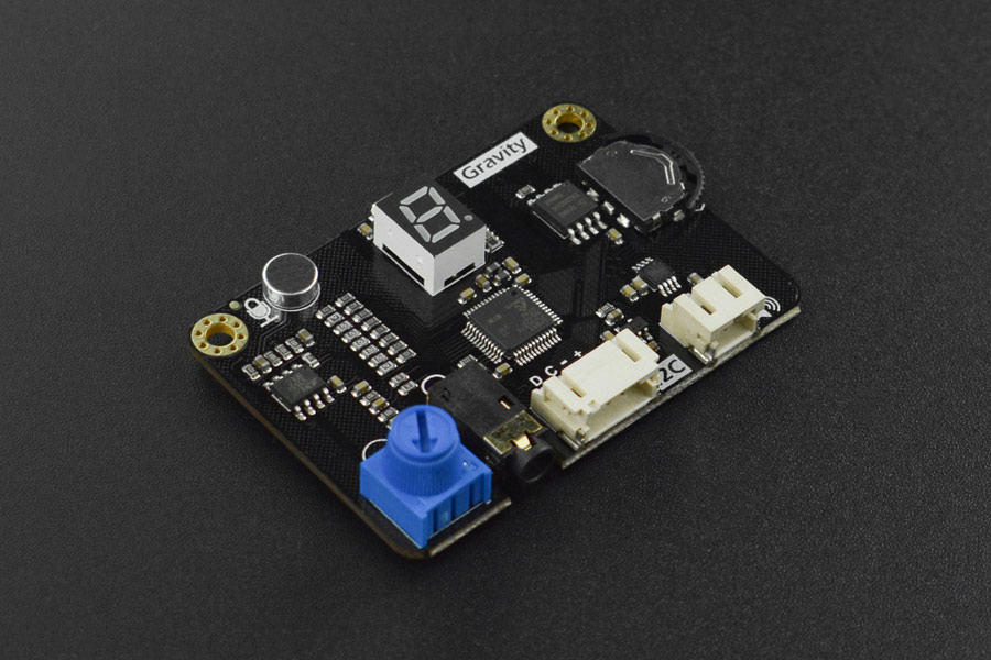
It also has a simplified speech synthesis function, for numbers 0 to 9 only. The built-in LED is very helpful when using the module.
- Off: No recording at the current number
- Yellow: There is a recording at the current number
- Red: Is recording
- Green: Is playing
- Flashing in red: Is deleting
Please see here for their official tutorial.
How to build a Simple Robot Arm with Servo Motor and Joystick
How to construct a robotic arm?
A simple robotic arm is basically like a human arm which consists of the upper arm, lower arm and hand (gripper). There are a lot of online resources for laser-cut files that you can use. After you have found one or designed one, you can go to the 3D Workshop to laser cut the hardware. In this tutorial, we will focus on how to control the servo motor (the joint of your robotic arm) with two potentiometers.
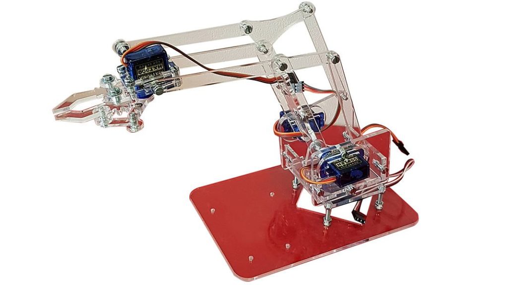
You can use more or less servo motors in your design based on how many joints you need. In this tutorial, we will use two servo motors, one for the rotation at the base and one for the angle of the upper arm.
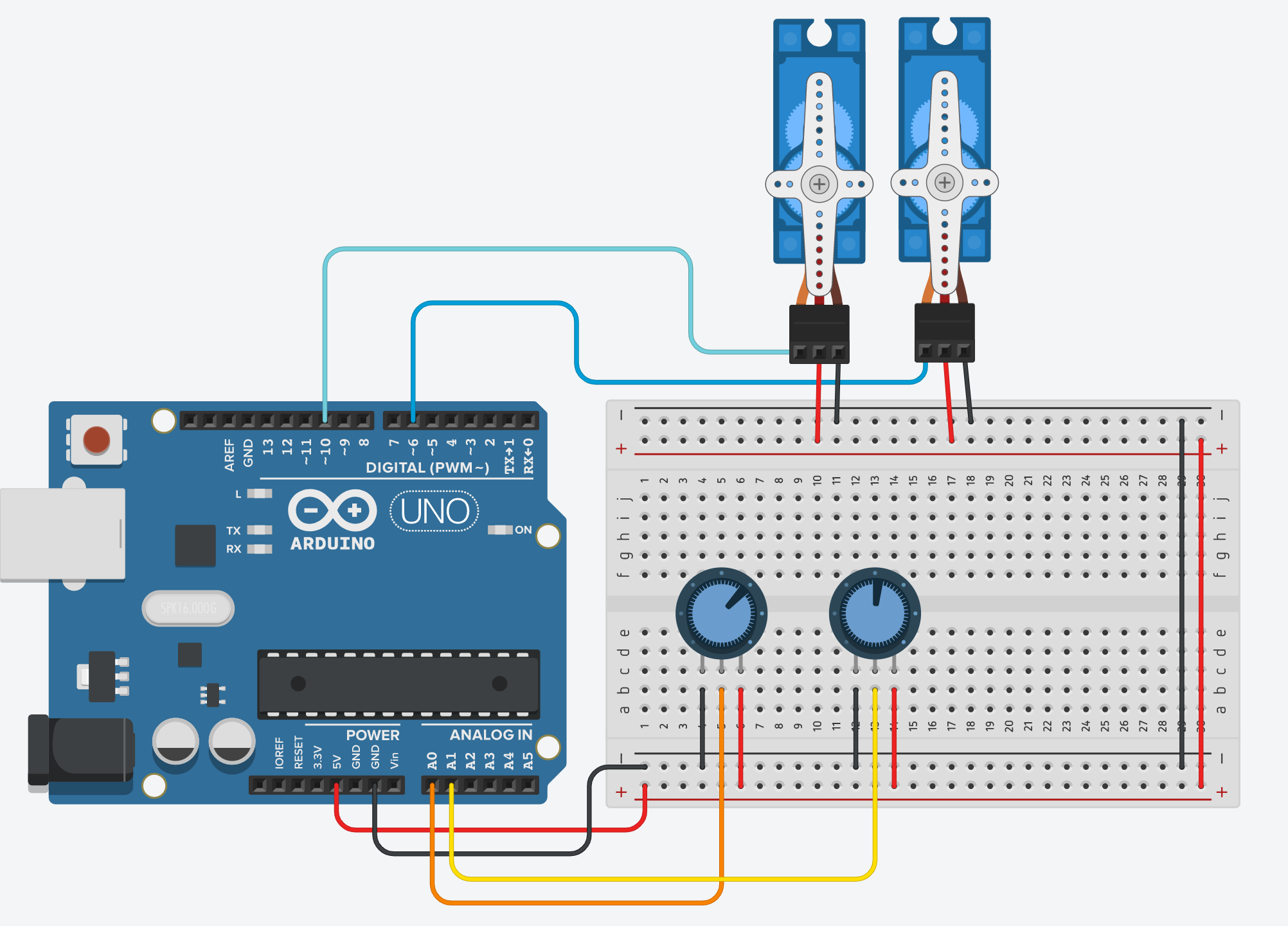
Wiring
- Servo: Power to 5V
- Servo: Ground to GND
- Servo: Signal to 6/10
- Potentiometer: Right pin to 5V
- Potentiometer: Left pin to GND
- Potentiometer: Middle pin to A0/A1
Getting started
This code is getting the servo motors to rotate based on the potentiometers' values.
#include <Servo.h>
#define potRotation A0
#define potAngle A1
#define servoRotation 10
#define servoAngle 6
// create servo object to control a servo
Servo rotateServo;
Servo angleServo;
void setup() {
Serial.begin(9600) ;
rotateServo.attach(servoRotation);
angleServo.attach(servoAngle);
}
void loop() {
// read analog potentiometer values
int rotation = analogRead(potRotation);
int angle = analogRead(potAngle);
int rotationMapped = map(rotation, 0, 1023, 0, 180); // scale it to the servo's angle (0 to 180)
int angleMapped = map(angle, 0, 1023, 0, 180); // scale it to the servo's angle (0 to 180)
rotateServo.write(rotationMapped); // rotate servo motor 1
angleServo.write(angleMapped); // rotate servo motor 2
// print data to Serial Monitor on Arduino IDE
Serial.print("potRotation: ");
Serial.print(rotation);
Serial.print(", potAngle:");
Serial.print(angle);
Serial.print(" => Servo Motor Rotation: ");
Serial.print(rotationMapped);
Serial.print("°, Angle:");
Serial.print(angleMapped);
Serial.println("°");
}
}
How to connect a Light Dependent Resistor (LDR)
What is an LDR?
An LDR or Light Dependent Resistor is a component which restricts how much power can flow through a circuit based on how much or little light hits the sensitive part on the top.

To use a Light Dependent Resistor, we have to use it in combination with a fixed value resistor, the combination of these two components acts a little like a kitchen mixer tap, we can vary the temperature (voltage) by adjusting the tap.

The zig-zag lines indicate resistors, the voltage output we measure with the Arduino comes from this middle point between the two, as the value of the LDR varies it changes the voltage between Ground (0V) and 5V (VCC).
Wiring
- (1)leg to 5V (Power)
- (2)leg split to GND via 10K resistor
- (2)leg split to A0

Getting started
The following code uses analogRead() to get a integer between 0-1023 representing the voltage, where 0 is 0V and 1023 is 5V.
The code below uses the serial port to output the value every 50ms to the Serial Monitor.
#define ldrPin A0
int value;
int limit;
void setup() {
Serial.begin( 9600 );
pinMode( ldrPin, INPUT );
pinMode(LED_BUILTIN, OUTPUT);
}
void loop() {
value = analogRead( ldrPin );
Serial.println( value );
if(value < limit){
digitalWrite(LED_BUILTIN, HIGH);
}else{
digitalWrite(LED_BUILTIN, LOW);
}
delay( 50 );
}
How to connect a push button or switch
What is are push buttons/switches?
There are dozens of different types of switches and buttons, but at their most basic is the momentary push button which we'll be focusing on in the wiring and getting started sections below. However the same approach applies to these as it does to any other type of button or switch.
Different types
- Rocker switch
- Push button
- Tactile button
- Reed switch
- Tilt switch
- Key operated switch
- Rotary switch
- Slide switch
- Micro switch
- Toggle switch
There are many different types for different purposes:


Rocker, slide and toggle switches work more like light switches holding their position, they can be a good way of indicating the mode of a device, such as playing video forward or backwards.

Micro switches can with motors to detect when it has reached the end of movement, such as in a 3D printer to stop the motor going too far over the end, or to detect if a draw is open or closed.
Wiring
Although a push button like that in the diagram only has two connections, which are closed by pressing the button, you have to add a resistor to make the circuit work properly.

It's not possible however to do this otherwise when you apply 5V by closing the circuit you would create a short circuit, instead we connect the Arduino pin through a high value 10KΩ resistor to ground, this allows the circuit to quickly reach 0V when the button is released but prevents large amounts of current flowing when the button is pressed.

Getting started
The following is a simple circuit that will get your button controlling the LED built into the Arduino.
#define ledPin 13
#define buttonPin 4
void setup() {
pinMode( ledPin, OUTPUT );
pinMode( buttonPin, INPUT );
}
void loop() {
boolean btnState = digitalRead( buttonPin );
if ( btnState == HIGH ) {
digitalWrite( ledPin, HIGH );
} else {
digitalWrite( ledPin, LOW );
}
}
If you want to add a toggle functionality such that one press causes the LED to come on, and another press then turns it off, so you don't have to hold the button down things get a little bit more complex.
The Arduino is a powerful computer and operates many times faster than human perception, as such when the mechanical push button is closed there is a small amount of 'bounce' where the circuit makes and breaks the connection a few times before it settles, this is detected by the Arduino as multiple presses.
 This diagram shows the signal bouncing up and down over a period of 10µS (0.00001 seconds)
In effect this means that each time you press the button to toggle just once it toggles multiple times, you can fix this either with a small capacitor, or modifications to your Arduino sketch.
The code here adds two major changes, first it tracks the current and previous button state through each loop meaning it can see if the button has changed from LOW to HIGH, and then adds a delay of 75ms to allow the button to settle but keep it fast enough that the user doesn't perceive this delay.
#define ledPin 13
#define buttonPin 4
boolean ledState = LOW;
boolean prevBtnState = LOW;
void setup() {
pinMode( ledPin, OUTPUT );
pinMode( buttonPin, INPUT );
}
void loop() {
boolean btnState = digitalRead( buttonPin );
if ( btnState == HIGH && prevBtnState == LOW ) {
ledState = ! ledState;
delay( 75 );
}
digitalWrite( ledPin, ledState );
prevBtnState = btnState;
}
How to control Arduino without using delay()
What is a delay()?
We have a tutorial about delay() and how to code without using it. Here we will try to simplify the process using the FireTimer library.
Replace delay()
There is an example that is modified from the built-in example Blink code which demonstrates controlling timing without using delay().
#include "FireTimer.h"
// Create a FireTimer object
FireTimer ledTimer;
void setup() {
// Initialize digital pin LED_BUILTIN as an output
pinMode(LED_BUILTIN, OUTPUT);
// Initialize the FireTimer with a delay of 1000 milliseconds
ledTimer.begin(1000);
}
void loop() {
// Check if the timer has fired
if (ledTimer.fire()) {
// Toggle the LED state
static bool ledState = LOW; // Keep track of the current LED state
ledState = !ledState; // Toggle the state
digitalWrite(LED_BUILTIN, ledState);
}
}
Change Timer in the loop()
This is the code to keep the LED on for 1 second and off for 2 seconds using the FireTimer library.
#include "FireTimer.h"
// Create a FireTimer object
FireTimer ledTimer;
void setup() {
// Initialize digital pin LED_BUILTIN as an output
pinMode(LED_BUILTIN, OUTPUT);
// Start the FireTimer with an initial delay of 1 second (LED ON duration)
ledTimer.begin(1000);
}
void loop() {
// Check if the timer has fired
if (ledTimer.fire()) {
// Toggle the LED state
static bool ledState = LOW; // Keep track of the current LED state
// Toggle the state
ledState = !ledState;
digitalWrite(LED_BUILTIN, ledState);
// Update the timer for the next duration:
// 1 second when LED is ON, 2 seconds when LED is OFF
if (ledState == HIGH) {
ledTimer.begin(1000); // LED is ON for 1 second
} else {
ledTimer.begin(2000); // LED is OFF for 2 seconds
}
}
}
Multiple Actuators and Multiple Timers
You can set up multiple timers for multiple actuators, like giving each person a watch and ask them to action based on their own watches.
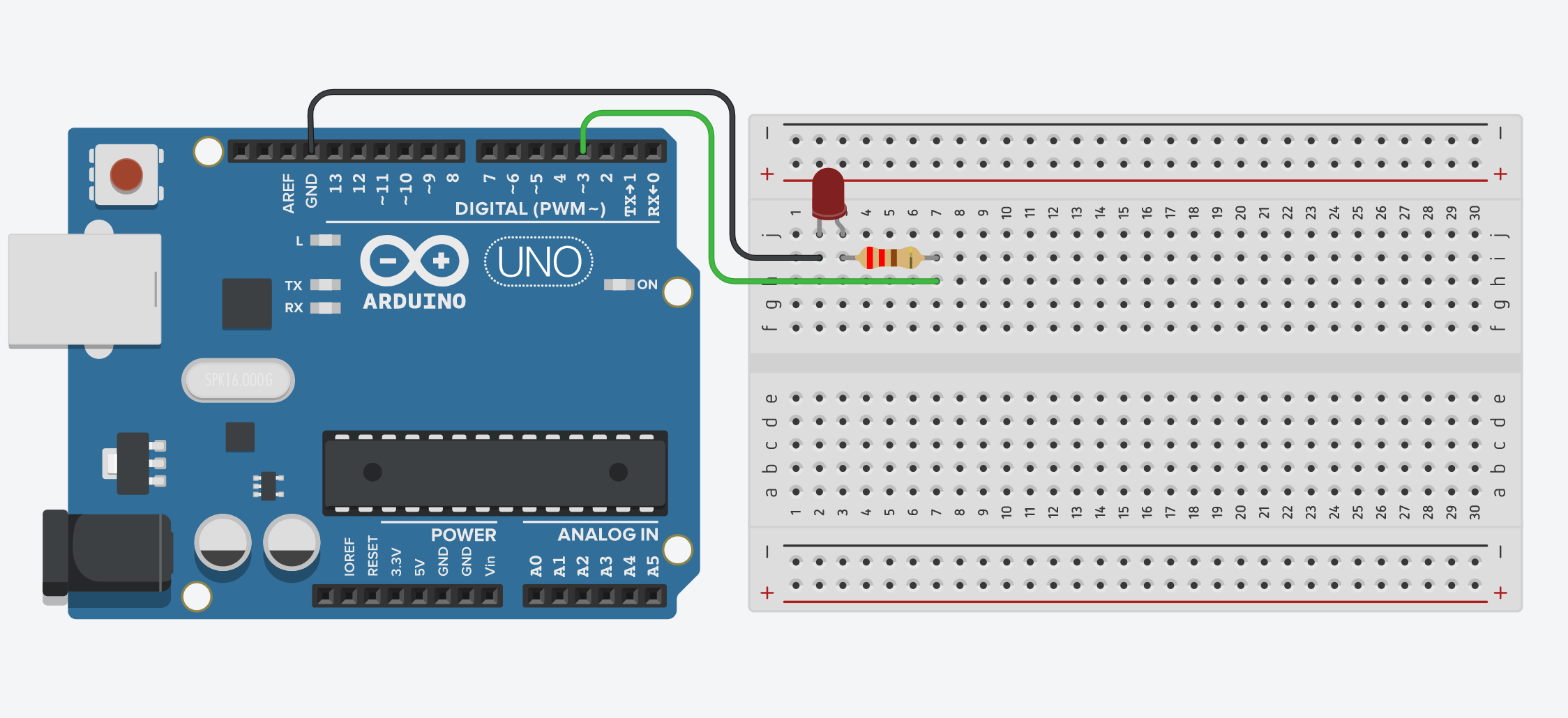
Wiring
There are three wires to connect on the Arduino side:
- LED short pin (-) to Ground
- LED long pin (+) to PWM Digital pin (D3), via 220Ω resistor
Code
In this code we are adding one more LED to the circuit. The built-in LED will stay the same, on and off every 1 second. The second LED will be one for 1 second and off for 5 second.
#include "FireTimer.h"
// Create FireTimer objects for two LEDs
FireTimer led1Timer; // Timer for LED1 (1-second interval)
FireTimer led2Timer; // Timer for LED2 (3-second interval)
const int LED1_PIN = 13; // Pin for the first LED
const int LED2_PIN = 3; // Pin for the second LED
void setup() {
// Initialize the LED pins as outputs
pinMode(LED1_PIN, OUTPUT);
pinMode(LED2_PIN, OUTPUT);
// Start the timers with their respective intervals
led1Timer.begin(1000); // LED1 blinks every 1 second
led2Timer.begin(3000); // LED2 blinks every 3 seconds
}
void loop() {
// Check if the timer for LED1 has fired
if (led1Timer.fire()) {
static bool led1State = LOW; // Keep track of LED1 state
led1State = !led1State; // Toggle LED1 state
digitalWrite(LED1_PIN, led1State);
}
// Check if the timer for LED2 has fired
if (led2Timer.fire()) {
static bool led2State = LOW; // Keep track of LED2 state
led2State = !led2State; // Toggle LED2 state
digitalWrite(LED2_PIN, led2State);
}
}
How to control Arduino without using delay()
What is a delay()?
delay() is a function that pauses the program for the amount of time (in milliseconds) specified as a parameter. (1000 milliseconds = 1 second.) delay() is very commonly used but it has its drawbacks. It does not just pause one sensor or actuator that you wish but pauses everything controlled by the same Arduino and the same code. This often leads to the slow down of sensors and thus is not accurate anymore.
read more
Getting started
There is a built-in example called BlinkWithoutDelay which demonstrates controlling timing without using delay(). Rather than pausing everything to keep the light on/off for a specific amount of time, we are setting up a timer to count the time for the actuator to action. In this example, you can see the value of the variable interval is actually equal to the same amount of delay() you will need to get the same result of blinking every 1 second.
// constants won't change. Used here to set a pin number:
const int ledPin = LED_BUILTIN; // the number of the LED pin
// Variables will change:
int ledState = LOW; // ledState used to set the LED
// Generally, you should use "unsigned long" for variables that hold time
// The value will quickly become too large for an int to store
unsigned long previousMillis = 0; // will store last time LED was updated
// constants won't change:
const long interval = 1000; // interval at which to blink (milliseconds)
void setup() {
// set the digital pin as output:
pinMode(ledPin, OUTPUT);
}
void loop() {
// check to see if it's time to blink the LED; that is, if the difference
// between the current time and last time you blinked the LED is bigger than
// the interval at which you want to blink the LED.
unsigned long currentMillis = millis();
if (currentMillis - previousMillis >= interval) {
// save the last time you blinked the LED
previousMillis = currentMillis;
// if the LED is off turn it on and vice-versa:
if (ledState == LOW) {
ledState = HIGH;
} else {
ledState = LOW;
}
// set the LED with the ledState of the variable:
digitalWrite(ledPin, ledState);
}
}
Multiple Actuators and Multiple Timers
You can set up multiple timers for multiple actuators, like giving each person a watch and ask them to action based on their own watches.
Wiring
There are three wires to connect on the Arduino side:
- LED short pin (-) to Ground
- LED long pin (+) to PWM Digital pin (D3), via 220Ω resistor
Code
In this code we are adding one more LED to the circuit. The built-in LED will stay the same, on and off every 1 second. The second LED will be one for 1 second and off for 5 second.
const int ledPin = LED_BUILTIN;
const int ledPin2 = 3;
unsigned long previousMillis = 0;
unsigned long previousMillis2 = 0;
void setup()
{
pinMode(ledPin, OUTPUT);
pinMode(ledPin2, OUTPUT);
}
void loop()
{
ledPattern();
ledPattern2();
}
void ledPattern(){
unsigned long currentMillis = millis();
digitalWrite(ledPin, LOW); //turn off at the beginning
//after 1s, light up, ie 1000
if (currentMillis - previousMillis >= 1000) {
digitalWrite(ledPin, HIGH);
}
//after light up for 1s, off, ie 1000+1000 = 2000
if (currentMillis - previousMillis >= 2000){
digitalWrite(ledPin, LOW);
//reset timer
previousMillis = currentMillis;
}
}
void ledPattern2(){
unsigned long currentMillis2 = millis();
digitalWrite(ledPin2, LOW); //turn off at the beginning
//after 5s, vibrate, ie 5000
if (currentMillis2 - previousMillis2 >= 5000) {
digitalWrite(ledPin2, HIGH);
}
//after vibrating for 1s, stop, ie 5000+1000 = 6000
if (currentMillis2 - previousMillis2 >= 6000){
digitalWrite(ledPin2, LOW);
//reset timer
previousMillis2 = currentMillis2;
}
}
How to install libraries
Arduino libraries are collections of code that are designed to provide additional, reusable functionality or to simplify using external electronic modules.
Libraries typically come with examples of how to use them. The library developer usually provides online documentation and explains how it possibly relates to what you are trying to achieve.
Installing a library
There are three different ways to install libraries; we'll show you each of them.
Arduino Library Manager
The simplest method of installing libraries is using the Library Manager built into the Arduino IDE.
You can access the Library Manager from the menu bar: Sketch - Include Library - Manage Libraries...

A new window will open:

From here you can search for libraries to use in your code. Only a few libraries are currently available this way, as this feature is relatively new. You will often have to manually download and install a library, following the other two processes.
ZIP library
Locate and download a library you wish to use. Sometimes the library will download as a *.zip archive, which can sometimes be installed directly without restarting the Arduino IDE.
Similar to the Library Manager, this option is in the menu bar:
Sketch - Include Library - Add .ZIP Library...

Use the file dialog to locate and select the zip file from your Downloads folder. You will be notified if the installation has been successful – otherwise you'll need to install manually.
Manually adding libraries
This is the original method of adding libraries.
- Locate the
Arduinofolder inside yourDocumentsdirectory. - Open the
librariesfolder. If not found, create a new folder with that name (must be lowercase). - Unzip the library archive that you wish to install.
- Inside the archive you should find a folder bearing the name of the library – for example 'MPR121'.
- Copy this entire folder (named 'MPR121' in our example) into the Arduino's
librariesfolder. - Restart the Arduino IDE.
- In the menu bar, select
Sketch>Include Library. You should now see that your library is listed.
How to make Animation on NeoMatrix
What is NeoMatrix?
NeoMatrix is a grid lined up with mutiple Neopixel. Neopixel is addressable LEDs, meaning that they can be programmed individually. With the library created by Adafruit, you can easily program the Neopixel strip for your project. They come in different sizes and shapes and you can shorten or lengthen them flexibly. Once set up, they are very durable and efficient. They are commonly found in a lot house decorations or light installations.We have a tutorial about Neopixel here.
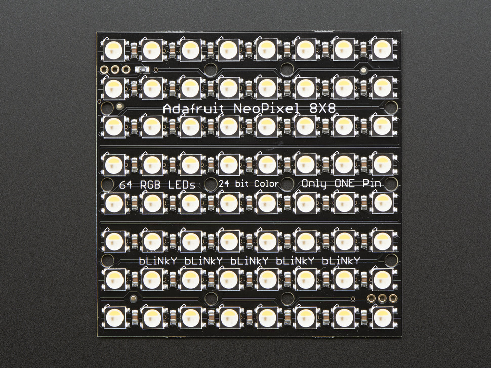
In this tutorial, we are using a 8x8 NeoMatrix from Adafruit.
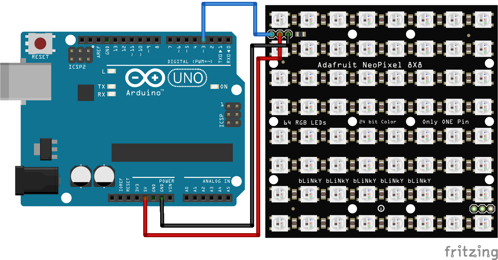
Wiring
- DIN to Pin3
- +5V to 5V
- GND to GND
Library
Warning
Download version 1.9.0 or below of Adafruit Neopixel library for a more stable performance.
We will need three libraries for this tutorial.
We have a tutorial on how to install a library here.
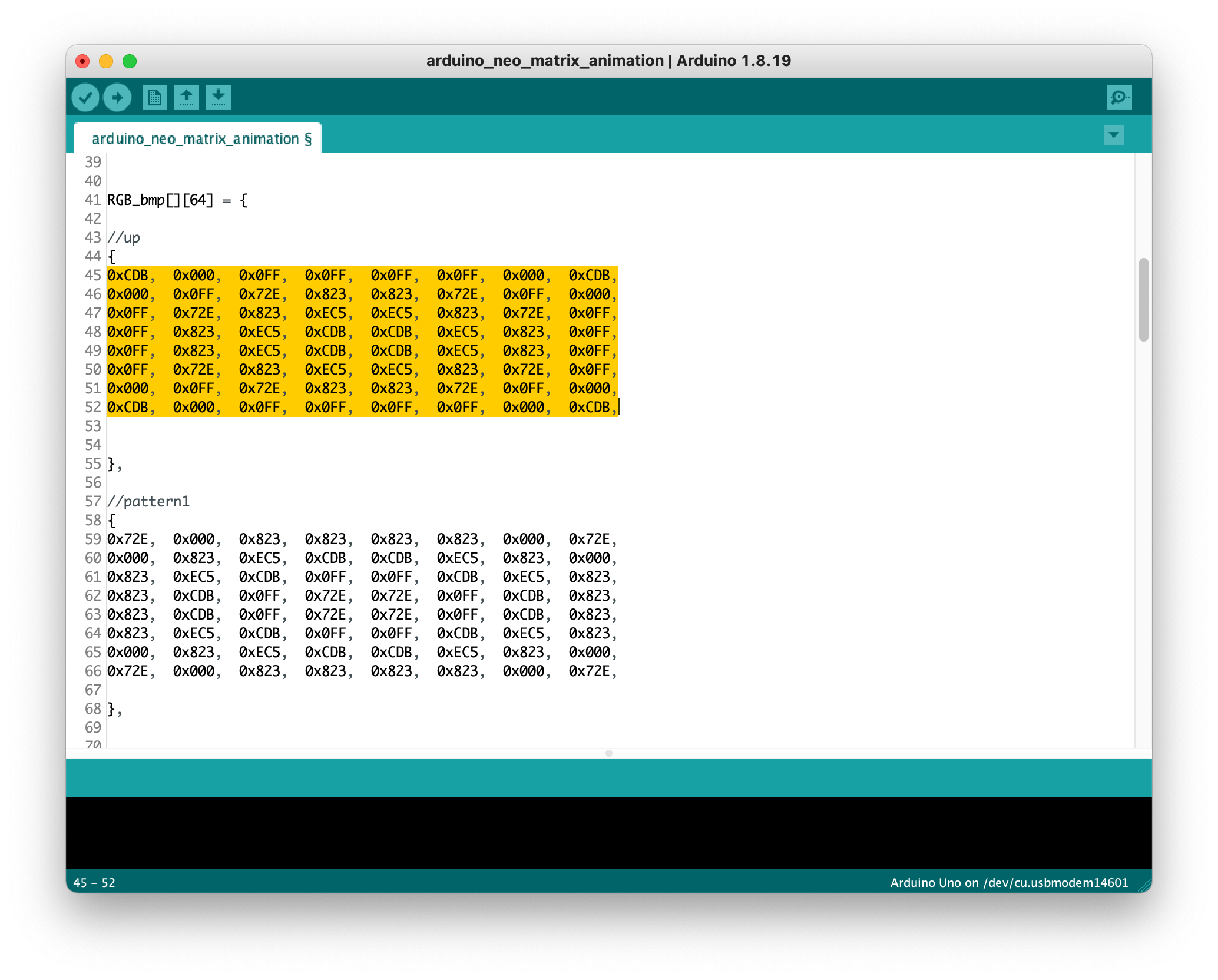
Getting started
The example shows the upward arrow first and then the animation of a colour-changing pattern. The upward arrow is for identifying the orientation of your matrix.
#include <Adafruit_GFX.h>
#include <Adafruit_NeoMatrix.h>
#include <Adafruit_NeoPixel.h>
// Which pin on the Arduino is connected to the NeoPixels?
#define PIN 3
// Max is 255, 32 is a conservative value to not overload
// a USB power supply (500mA) for 12x12 pixels.
#define BRIGHTNESS 50
// Define matrix width and height.
#define mw 8
#define mh 8
#define LED_BLACK 0
int counter = 0;
int numImage = 0;
// When we setup the NeoPixel library, we tell it how many pixels, and which pin to use to send signals.
// Note that for older NeoPixel strips you might need to change the third parameter--see the strandtest
// example for more information on possible values.
Adafruit_NeoMatrix *matrix = new Adafruit_NeoMatrix(mw, mh, PIN,
NEO_MATRIX_TOP + NEO_MATRIX_LEFT +
NEO_MATRIX_ROWS + NEO_MATRIX_ZIGZAG,
NEO_GRB + NEO_KHZ800);
static const uint16_t PROGMEM
// These bitmaps were written for a backend that only supported
// 4 bits per color with Blue/Green/Red ordering while neomatrix
// uses native 565 color mapping as RGB.
// I'm leaving the arrays as is because it's easier to read
// which color is what when separated on a 4bit boundary
// The demo code will modify the arrays at runtime to be compatible
// with the neomatrix color ordering and bit depth.
RGB_bmp[][64] = {
//up for identifying direction
{
0x000, 0x000, 0x000, 0x5C9, 0x5C9, 0x000, 0x000, 0x000,
0x000, 0x000, 0x5C9, 0x5C9, 0x5C9, 0x5C9, 0x000, 0x000,
0x000, 0x5C9, 0x000, 0x5C9, 0x5C9, 0x000, 0x5C9, 0x000,
0x5C9, 0x000, 0x000, 0x5C9, 0x5C9, 0x000, 0x000, 0x5C9,
0x000, 0x000, 0x000, 0x5C9, 0x5C9, 0x000, 0x000, 0x000,
0x000, 0x000, 0x000, 0x5C9, 0x5C9, 0x000, 0x000, 0x000,
0x000, 0x000, 0x000, 0x5C9, 0x5C9, 0x000, 0x000, 0x000,
0x000, 0x000, 0x000, 0x5C9, 0x5C9, 0x000, 0x000, 0x000,
},
//pattern1
{
0x72E, 0x000, 0x823, 0x823, 0x823, 0x823, 0x000, 0x72E,
0x000, 0x823, 0xEC5, 0xCDB, 0xCDB, 0xEC5, 0x823, 0x000,
0x823, 0xEC5, 0xCDB, 0x0FF, 0x0FF, 0xCDB, 0xEC5, 0x823,
0x823, 0xCDB, 0x0FF, 0x72E, 0x72E, 0x0FF, 0xCDB, 0x823,
0x823, 0xCDB, 0x0FF, 0x72E, 0x72E, 0x0FF, 0xCDB, 0x823,
0x823, 0xEC5, 0xCDB, 0x0FF, 0x0FF, 0xCDB, 0xEC5, 0x823,
0x000, 0x823, 0xEC5, 0xCDB, 0xCDB, 0xEC5, 0x823, 0x000,
0x72E, 0x000, 0x823, 0x823, 0x823, 0x823, 0x000, 0x72E,
},
//pattern2
{
0x823, 0x000, 0xEC5, 0xEC5, 0xEC5, 0xEC5, 0x000, 0x823,
0x000, 0xEC5, 0xCDB, 0x0FF, 0x0FF, 0xCDB, 0xEC5, 0x000,
0xEC5, 0xCDB, 0x0FF, 0x72E, 0x72E, 0x0FF, 0xCDB, 0xEC5,
0xEC5, 0x0FF, 0x72E, 0x823, 0x823, 0x72E, 0x0FF, 0xEC5,
0xEC5, 0x0FF, 0x72E, 0x823, 0x823, 0x72E, 0x0FF, 0xEC5,
0xEC5, 0xCDB, 0x0FF, 0x72E, 0x72E, 0x0FF, 0xCDB, 0xEC5,
0x000, 0xEC5, 0xCDB, 0x0FF, 0x0FF, 0xCDB, 0xEC5, 0x000,
0x823, 0x000, 0xEC5, 0xEC5, 0xEC5, 0xEC5, 0x000, 0x823,
},
//pattern3
{
0xEC5, 0x000, 0xCDB, 0xCDB, 0xCDB, 0xCDB, 0x000, 0xEC5,
0x000, 0xCDB, 0x0FF, 0x72E, 0x72E, 0x0FF, 0xCDB, 0x000,
0xCDB, 0x0FF, 0x72E, 0x823, 0x823, 0x72E, 0x0FF, 0xCDB,
0xCDB, 0x72E, 0x823, 0xEC5, 0xEC5, 0x823, 0x72E, 0xCDB,
0xCDB, 0x72E, 0x823, 0xEC5, 0xEC5, 0x823, 0x72E, 0xCDB,
0xCDB, 0x0FF, 0x72E, 0x823, 0x823, 0x72E, 0x0FF, 0xCDB,
0x000, 0xCDB, 0x0FF, 0x72E, 0x72E, 0x0FF, 0xCDB, 0x000,
0xEC5, 0x000, 0xCDB, 0xCDB, 0xCDB, 0xCDB, 0x000, 0xEC5,
},
//pattern4
{
0xCDB, 0x000, 0x0FF, 0x0FF, 0x0FF, 0x0FF, 0x000, 0xCDB,
0x000, 0x0FF, 0x72E, 0x823, 0x823, 0x72E, 0x0FF, 0x000,
0x0FF, 0x72E, 0x823, 0xEC5, 0xEC5, 0x823, 0x72E, 0x0FF,
0x0FF, 0x823, 0xEC5, 0xCDB, 0xCDB, 0xEC5, 0x823, 0x0FF,
0x0FF, 0x823, 0xEC5, 0xCDB, 0xCDB, 0xEC5, 0x823, 0x0FF,
0x0FF, 0x72E, 0x823, 0xEC5, 0xEC5, 0x823, 0x72E, 0x0FF,
0x000, 0x0FF, 0x72E, 0x823, 0x823, 0x72E, 0x0FF, 0x000,
0xCDB, 0x000, 0x0FF, 0x0FF, 0x0FF, 0x0FF, 0x000, 0xCDB,
},
//pattern5
{
0x0FF, 0x000, 0x72E, 0x72E, 0x72E, 0x72E, 0x000, 0x0FF,
0x000, 0x72E, 0x823, 0xEC5, 0xEC5, 0x823, 0x72E, 0x000,
0x72E, 0x823, 0xEC5, 0xCDB, 0xCDB, 0xEC5, 0x823, 0x72E,
0x72E, 0xEC5, 0xCDB, 0x0FF, 0x0FF, 0xCDB, 0xEC5, 0x72E,
0x72E, 0xEC5, 0xCDB, 0x0FF, 0x0FF, 0xCDB, 0xEC5, 0x72E,
0x72E, 0x823, 0xEC5, 0xCDB, 0xCDB, 0xEC5, 0x823, 0x72E,
0x000, 0x72E, 0x823, 0xEC5, 0xEC5, 0x823, 0x72E, 0x000,
0x0FF, 0x000, 0x72E, 0x72E, 0x72E, 0x72E, 0x000, 0x0FF,
},
};
void display_rgbBitmap(uint8_t bmp_num) {
static uint16_t bmx, bmy;
fixdrawRGBBitmap(bmx, bmy, RGB_bmp[bmp_num], 8, 8);
bmx += 8;
if (bmx >= mw) bmx = 0;
if (!bmx) bmy += 8;
if (bmy >= mh) bmy = 0;
matrix->show();
}
// Convert a BGR 4/4/4 bitmap to RGB 5/6/5 used by Adafruit_GFX
void fixdrawRGBBitmap(int16_t x, int16_t y, const uint16_t *bitmap, int16_t w, int16_t h) {
uint16_t RGB_bmp_fixed[w * h];
for (uint16_t pixel = 0; pixel < w * h; pixel++) {
uint8_t r, g, b;
uint16_t color = pgm_read_word(bitmap + pixel);
//Serial.print(color, HEX);
b = (color & 0xF00) >> 8;
g = (color & 0x0F0) >> 4;
r = color & 0x00F;
//Serial.print(" ");
//Serial.print(b);
//Serial.print("/");
//Serial.print(g);
//Serial.print("/");
//Serial.print(r);
//Serial.print(" -> ");
// expand from 4/4/4 bits per color to 5/6/5
b = map(b, 0, 15, 0, 31);
g = map(g, 0, 15, 0, 63);
r = map(r, 0, 15, 0, 31);
//Serial.print(r);
//Serial.print("/");
//Serial.print(g);
//Serial.print("/");
//Serial.print(b);
RGB_bmp_fixed[pixel] = (r << 11) + (g << 5) + b;
// Serial.print(" -> ");
//Serial.print(pixel);
//Serial.print(" -> ");
//Serial.println(RGB_bmp_fixed[pixel], HEX);
}
matrix->drawRGBBitmap(x, y, RGB_bmp_fixed, w, h);
}
void setup() {
Serial.begin(115200);
matrix->begin();
matrix->setTextWrap(false);
matrix->setBrightness(BRIGHTNESS);
// Test full bright of all LEDs. If brightness is too high
// for your current limit (i.e. USB), decrease it.
//matrix->fillScreen(LED_WHITE_HIGH);
//matrix->show();
//delay(1000);
matrix->clear();
numImage=(sizeof(RGB_bmp) / sizeof(RGB_bmp[0]));
Serial.print("Number of images: ");
Serial.println(numImage);
}
void loop() {
// clear the screen after X bitmaps have been displayed and we
// loop back to the top left corner
// 8x8 => 1, 16x8 => 2, 17x9 => 6
static uint8_t pixmap_count = ((mw + 7) / 8) * ((mh + 7) / 8);
// Cycle through red, green, blue, display 2 checkered patterns
// useful to debug some screen types and alignment.
Serial.print("Screen pixmap capacity: ");
Serial.println(pixmap_count);
display_rgbBitmap(counter++);
delay(500);
if (counter >=numImage){
counter = 0;
}
Serial.println ("----------------------------------------------------------------");
//delay(1000);
}
You should see your Neopixel displaying the animation frame by frame right now.
Creating your own Animation
To create the animation, we have to convert your animation into HEX code frame by frame. We have an Excel file you can download to do that.
1. Enable Macros for Excel

2. Set up your Matrix
Type in the number of row and column (blue boxes) and then press Update Color_Pixel Page.
![]()
3. Create your Frame
Go to the Color_Pixel Tab, and start filling your Matrix with colours. Black means turning off that LED.
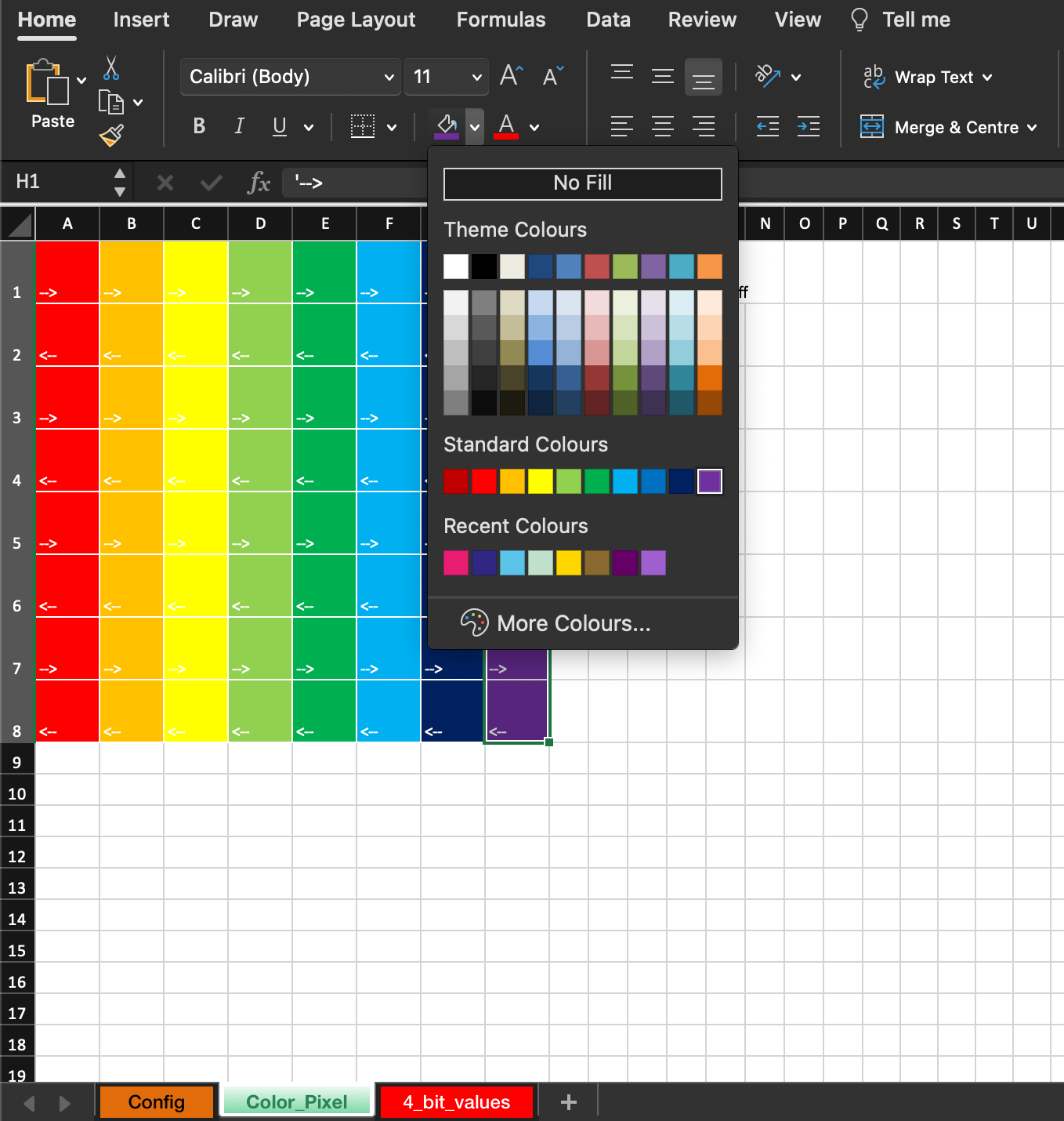
4. Convert your Frame to Code
When you are happy with your design, go to the Config Tab and press Update 4 Bit Values.

5. Copy your Code
Copy the Code in the 4_bit_values.
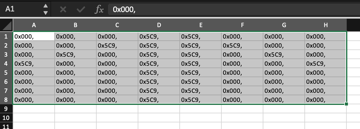
6. Paste your Code in Arduino IDE
The yellow highlighted part within {} will be the code to be replaced. Upload, then you are good to go!
How to make Animation on NeoMatrix with Processing
Controlling NeoMatrix with Processing
This tutorial is a follow-up to the last NeoMatrix animation tutorial. We are using Processing to create images, videos or realtime interaction and push those to an 8x8 Adafruit NeoMatrix.
Wiring
Warning
If you have a bigger matrix, you will need an extra power supply. The extra power supply will share the ground with Arduino and the matrix.
- DIN to Pin3
- +5V to 5V
- GND to GND
Library
Warning
Download version 1.9.0 or below of Adafruit Neopixel library for a more stable performance.
We will need three libraries for this tutorial.
We have a tutorial on how to install a library here.
Understand your Matrix
When programming the matrix, it is important to know the configuration of your matrix so that the x and y coordinates sent from Processing can be matched. The most important two are the starting point and the arrangement.
The Starting Point
the starting point: Usually it will be the Top Left. If you are building your own Matrix from scratch, it will be easier to program later if you choose the top left corner as your first pixel as 0,0 in Processing is the top left corner by default.
![]()
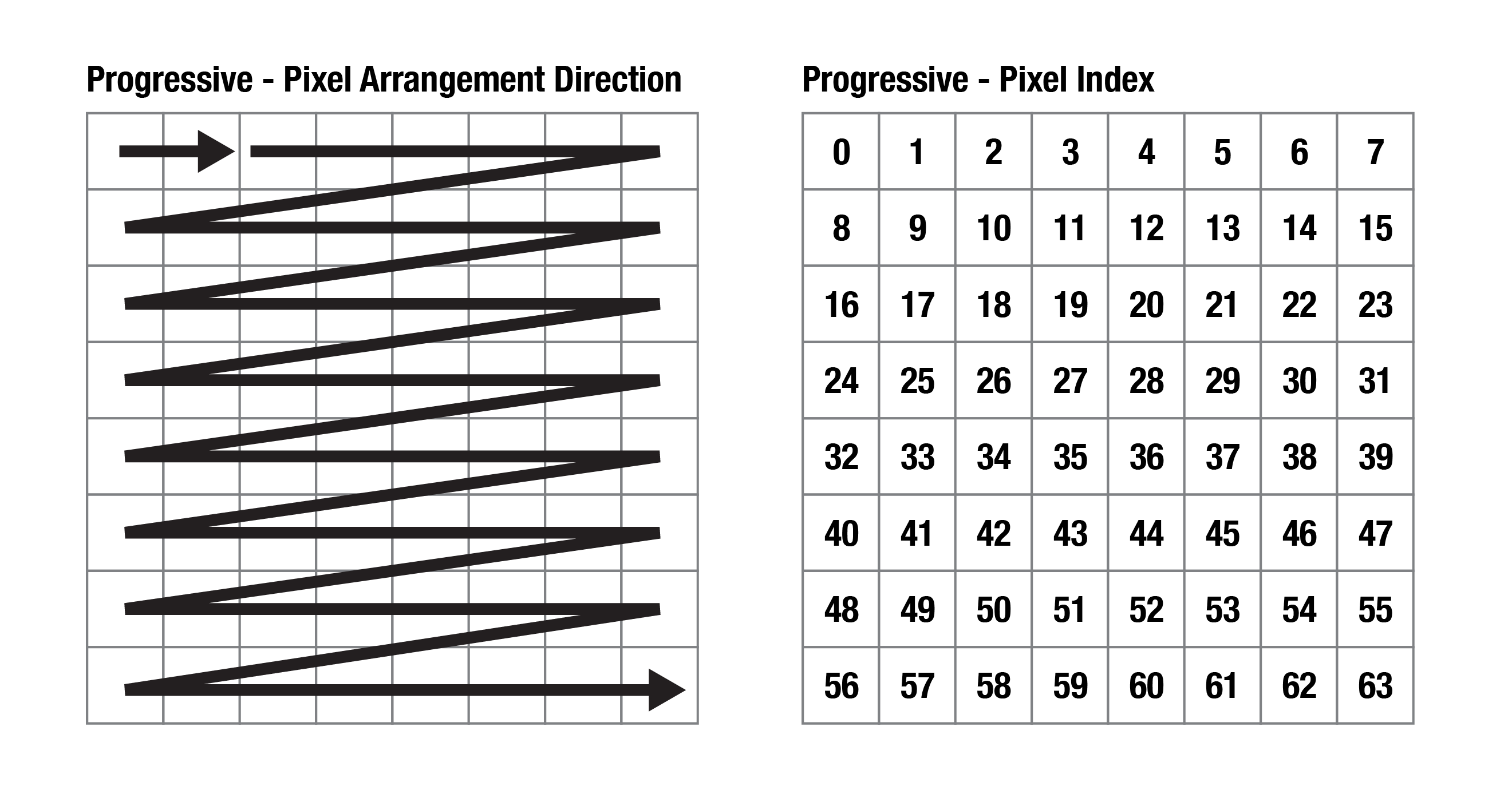
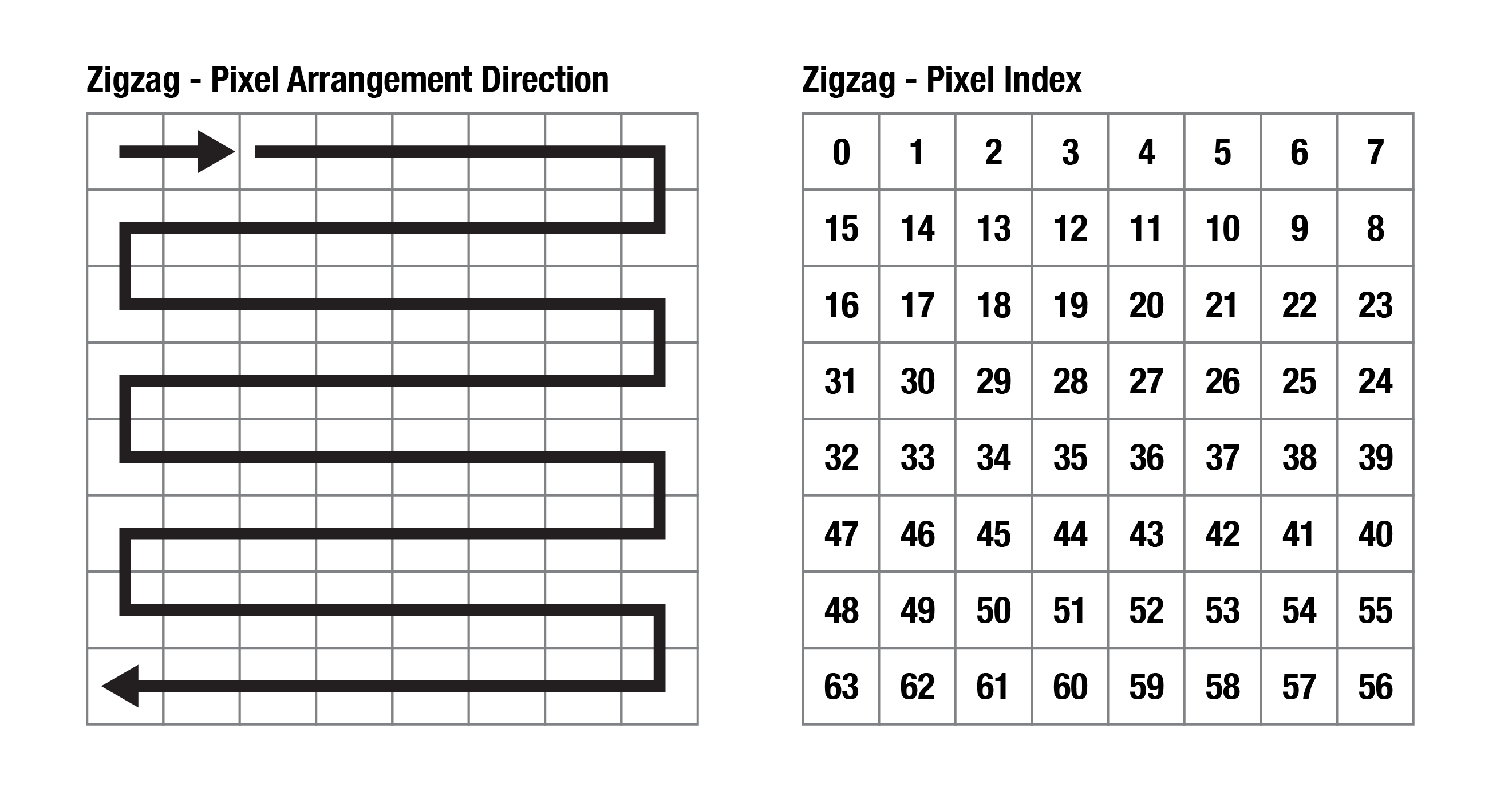
The Arrangement
There are two types, Progressive and Zigzag.
Progressive: Adafruit's pre-built matrix is using this arrangement. It will make coding easier as the pixel index in Processing will be exactly the same as the pixel number on the Matrix. You don't have to alternate numbers for even-numbered rows.
Zigzag: It will be a more popular choice of arrangement for building a matrix from scratch as it involves shorter connections and it is easier for soldering.
If you have a second-hand matrix and are not sure about its configuration, you can run the strandtest code to see how the lights light up one by one.
Processing Code
We have a tutorial about serial communication between Processing and Arduino so I will skip it here. In this example code, you can draw with your mouse on the screen and the matrix will light up accordingly.
Before setup(), you will need to change the values of cols, rows, pixelSize and size(cols*pixelSize , rows*pixelSize); to fit your own project. Please read the comments in the code to see what they represent.
You can put the content that you wish to push to the matrix between loadPixels(); and updatePixels();.
loadPixels(); loads the pixel data of the current display window into the pixels[] array. The pixels[] array contains the colour values for all the pixels in the display window.
updatePixels(); is only necessary if the display has changed, e.g. video, interactive/generative graphic.
Learn more about images and pixels in Processing here.
import processing.serial.*;
Serial arduino;
int cols = 8; // Number of NeoPixel matrix columns
int rows = 8; // Number of NeoPixel matrix rows
int totalLEDs = cols * rows;
int pixelSize = 50; // Adjust this based on your webcam's resolution
int i = 0;
int blue = 0;
void setup() {
size(400, 400); // size(cols*pixelSize , rows*pixelSize);
background(0);
// Set up serial communication with Arduino
printArray(Serial.list());
arduino = new Serial(this, Serial.list()[1], 115200); // Change baud rate if needed
}
void draw() {
//clear
if (keyPressed == true) {
background(0);
}
loadPixels(); //load pixel for neomatrix
int x = i % cols;
int y = i / cols;
int loc = x + y * width/pixelSize;
int cloc = (x*pixelSize + pixelSize/2) + y*pixelSize * width;
color c = pixels[cloc];
int r = (c >> 16) & 0xFF;
int g = (c >> 8) & 0xFF;
int b = c & 0xFF;
//println(i);
arduino.write(loc); //for progressive arrangement
//arduino.write(x); //for zigzag arrangement
//arduino.write(y); //for zigzag arrangement
arduino.write(r);
arduino.write(g);
arduino.write(b);
delay(10); // Small delay for stability
i++;
if (i >= totalLEDs){
i = 0;
}
updatePixels();
}
void mouseDragged() {
noStroke();
fill(0,125,blue, 50);
ellipse(mouseX,mouseY,pixelSize, pixelSize);
blue ++;
if (blue >= 255){
blue = 0;
}
}
Arduino Code
The following code is for an 8x8 Adafruit NeoMatrix with the below configurations.
- the starting point: Top Left
- the arrangement: Progressive
#include <Adafruit_NeoPixel.h>
int w = 8; //width of matrix
int h = 8; //height of matrix
#define PIN 3 // Pin connected to the NeoPixels
#define NUMPIXELS w*h // Number of NeoPixels (16x16 matrix)
Adafruit_NeoPixel strip = Adafruit_NeoPixel(NUMPIXELS, PIN, NEO_GRB + NEO_KHZ800);
void setup() {
strip.begin();
strip.show(); // Initialize all pixels to 'off'
strip.setBrightness(5); //I set a super low brightness as it's easier for my eyes during prototyping.
Serial.begin(115200); // Set the baud rate to match Processing
}
void loop() {
//------------------------for progressive arrangement ----------------------------------
if (Serial.available() >= 4) { // Ensure complete location & RGB data received
int loc = Serial.read();
int r = Serial.read();
int g = Serial.read();
int b = Serial.read();
//------------------------for progressive arrangement ----------------------------------
/*
//------------------------for zigzag arrangement ----------------------------------
if (Serial.available() >= 5) { // Ensure complete x,y coordinates & RGB data received
int x = Serial.read();
int y = Serial.read();
int r = Serial.read();
int g = Serial.read();
int b = Serial.read();
// Calculate pixel index based on zigzag layout (adjust the logic as needed)
int loc;
if (y % 2 == 0) {
loc = y * w + x; // If even row, use regular indexing
} else {
loc = (y * w) + (w-1 - x); // If odd row, reverse indexing
}
//------------------------for zigzag arrangement ----------------------------------
*/
strip.setPixelColor(loc, strip.Color(r, g, b)); // Control NeoPixels using received RGB values
strip.show(); // Display the updated NeoPixel colors
}
}
Disadvantage for this Setup
We are only using the bare minimum of components and Serial communication for sending data, so the matrix will not update everything all at once instantly. It will update and light up the pixels one by one which I find to be quite artistic for my taste.
Have fun!
How to Program an ATtiny85 with an Arduino Uno
What is an ATtiny85?
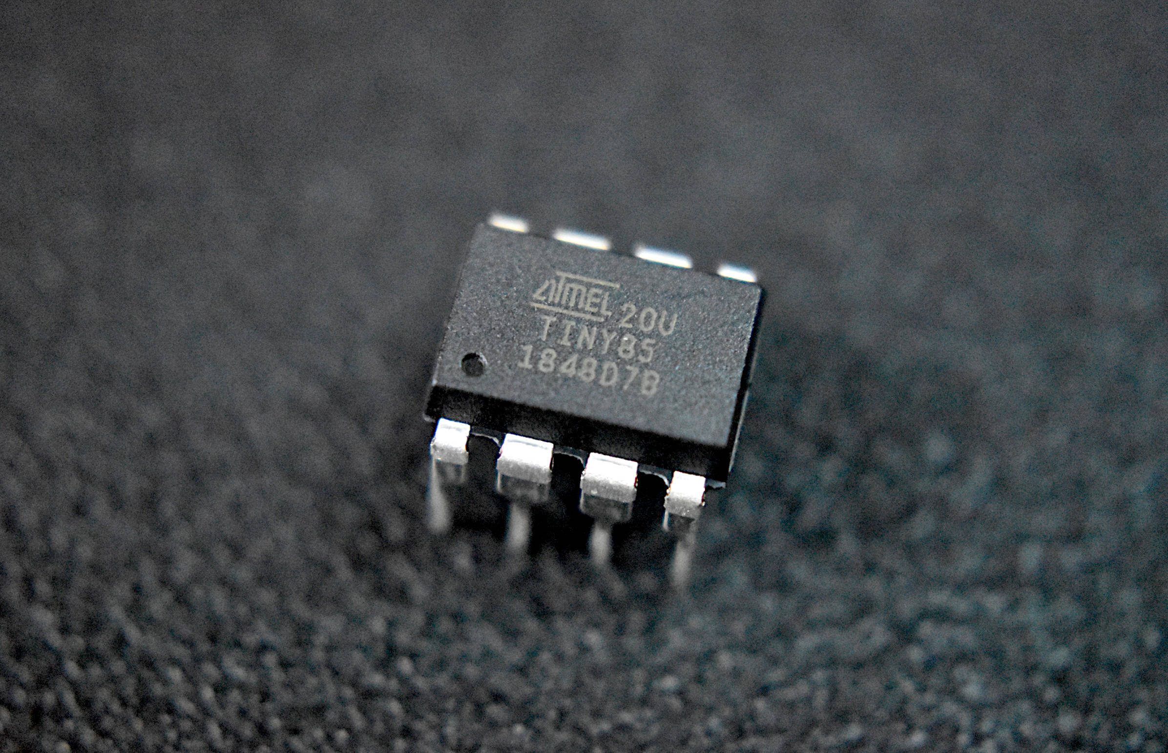
ATtiny85 is a 8-bit AVR microcontroller based on AVR enhanced RISC architecture. It has an 8-pin interface (PDIP) and comes in the category of low-power microcontrollers. This microcontroller is designed and manufactured by Microchip. Know More
Set the Arduino Uno Into ISP Mode
So that the Arduino can act as a device to upload code to ATtiny85.
File - Examples - Arduino ISP - ArduinoISP
Add this line #define USE_OLD_STYLE_WIRING to the code before setup()
UPLOAD!
Wiring
The pins are not labelled so you will have to refer to the pinout.
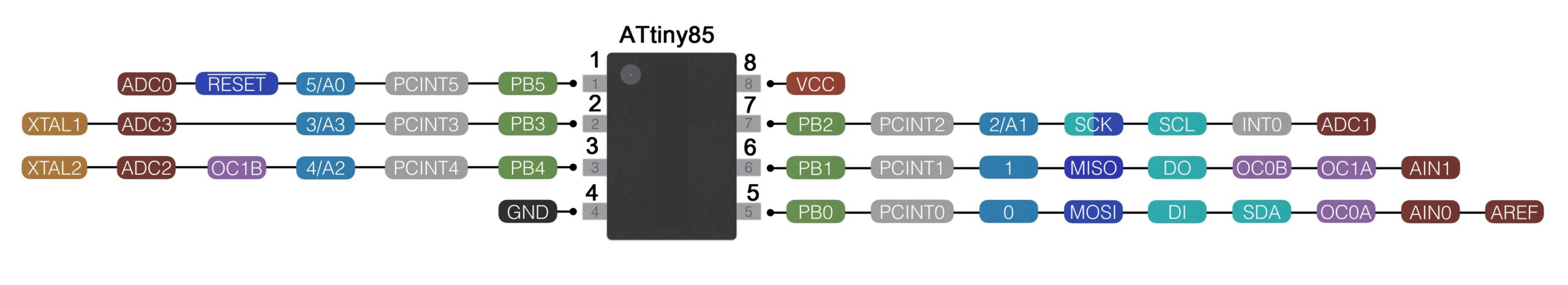 Arduino --> ATtiny85
- 5V --> Vcc (8)
- GND --> GND (4)
- Pin 13 --> Pin 2 (7)
- Pin 12 --> Pin 1 (6)
- Pin 11 --> Pin 0 (5)
- Pin 10 --> Reset (1)
Only when you are uploading code to ATtiny85
Put a 10uF capacitor between GND and RESET on Arduino
Adding Attiny85 to Boards Manager
We have to make ATtiny compatible with Arduino IDE first, so that we can choose ATting85 from Tools -> Board
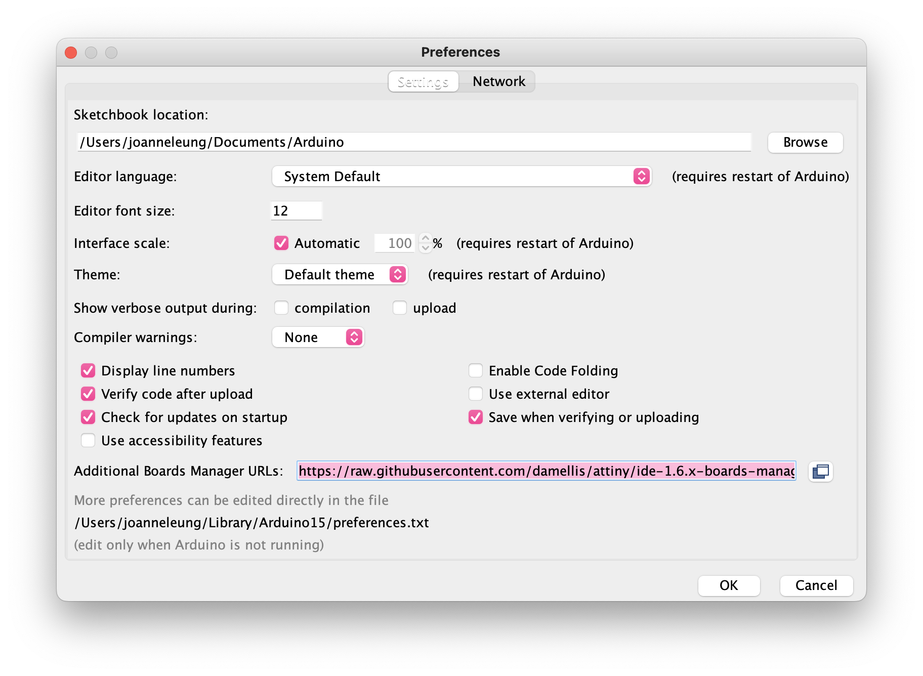
Go to Arduino Preference
Copy the below code and paste it into Additional Boards Manager URLs, if you already have a board manager URL just add a comma before pasting. Click OK and restart Arduino IDE.
https://raw.githubusercontent.com/damellis/attiny/ide-1.6.x-boards-manager/package_damellis_attiny_index.json
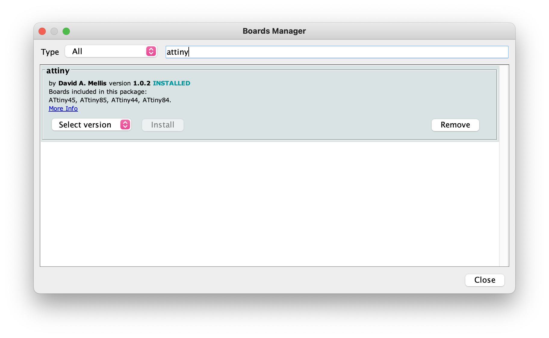
Go to Tools - Board - Boards Manager, search for ATtiny, then install!
Get Started
Before uploading the code, we have to change some settings.
- Tools -> Board scroll to the bottom select ATtiny25/45/85
- Tools -> Processor--> 8 MHz (internal)
- Tools-->Programmer-->Arduino as ISP
- Check that all wiring, capacitor, and board selections are correct.
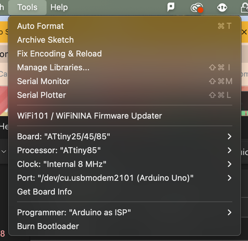
Open up a basic code and upload as usual!
If it doesn't work, try Tools - Burn Bootloader
How to send data to p5.js from Arduino
What is the Serial Communication?
Serial communication is the process of sending data one bit at a time, sequentially, over a communication channel or computer bus. Simply put, serial communication is the communication between two or more computers with binary data.
In this tutorial, we will use serial communication protocol to send data to p5.js from Arduino using the P5.js WebSerial Library. The p5.js sketch will be controlled by the physical component, the potentiometer, which can be replaced with other sensors, button and etc. Know more about the Web Serial API.
Wiring
- Left pin to 5V
- Right pin to GND
- middle pin to A0
Arduino Code
This example sends the potentiometer value measured from Arduino to p5.js via the serial port, you can read the data from the serial monitor.
#define potPin A0
int value;
void setup() {
Serial.begin(9600); //intailise Serial communication with 9600 baud rate
pinMode( potPin, INPUT );
}
void loop() {
value = analogRead( potPin);
Serial.println(value); //read the sensor and send the value to the Serial
delay(100); //little delay to prevent Arduino going crazy
}
p5.js Code
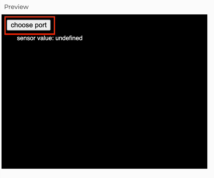
This example will show the incoming data from Arduino on the canvas.
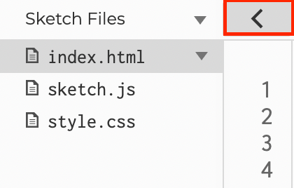
A p5.js sketch is actually a website that consists of a html file, a css file and a java script which makes everything fun. To access different files in your sketch, you can click the arrow and the panel on the left will show the files associated with the sketch.
First we have to install the P5.js WebSerial Library.
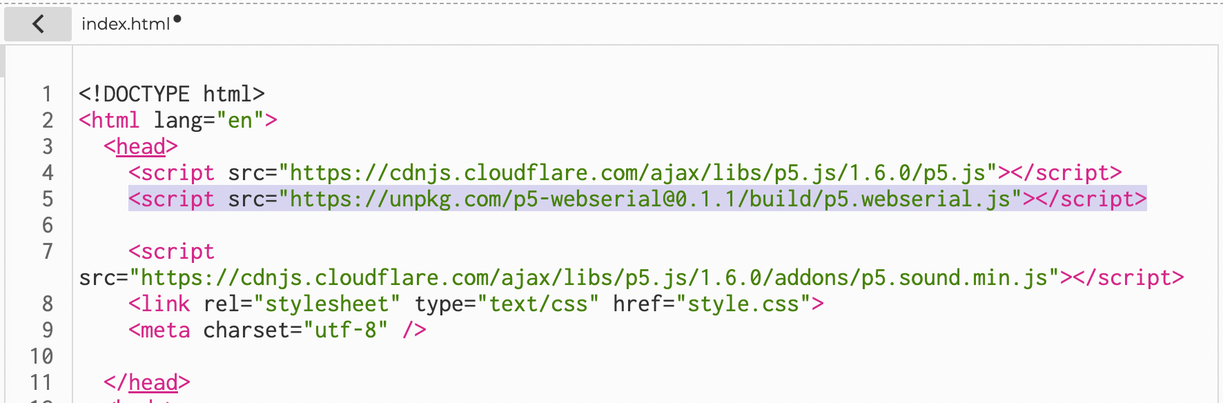
You have to place the below script in the index.html file, inside the <head>.
<script src="https://unpkg.com/p5-webserial@0.1.1/build/p5.webserial.js"></script>
It should look like this.
The below is the example code that should be placed in the sketch.js file. Please read the comments in the code to understand what they do.
// variable to hold an instance of the p5.webserial library:
const serial = new p5.WebSerial();
// HTML button object:
let portButton;
let inData; // for incoming serial data
let outByte = 0; // for outgoing data
let vals = [];
function setup() {
createCanvas(400, 300); // make the canvas
// check to see if serial is available:
if (!navigator.serial) {
alert("WebSerial is not supported in this browser. Try Chrome or MS Edge.");
}
// if serial is available, add connect/disconnect listeners:
navigator.serial.addEventListener("connect", portConnect);
navigator.serial.addEventListener("disconnect", portDisconnect);
serial.getPorts(); // check for any ports that are available:
serial.on("noport", makePortButton); // if there's no port chosen, choose one:
serial.on("portavailable", openPort); // open whatever port is available:
serial.on("requesterror", portError); // handle serial errors:
serial.on("data", serialEvent); // handle any incoming serial data:
serial.on("close", makePortButton);
}
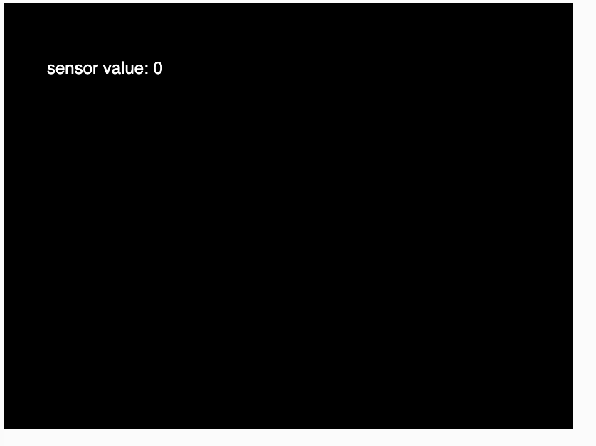
function draw() {
background(0);
fill(255);
text("sensor value: " + inData, 30, 50);
}
// if there's no port selected,
// make a port select button appear:
function makePortButton() {
// create and position a port chooser button:
portButton = createButton("choose port");
portButton.position(10, 10);
// give the port button a mousepressed handler:
portButton.mousePressed(choosePort);
}
// make the port selector window appear:
function choosePort() {
if (portButton) portButton.show();
serial.requestPort();
}
// open the selected port, and make the port
// button invisible:
function openPort() {
// wait for the serial.open promise to return,
// then call the initiateSerial function
serial.open().then(initiateSerial);
// once the port opens, let the user know:
function initiateSerial() {
console.log("port open");
}
// hide the port button once a port is chosen:
if (portButton) portButton.hide();
}
// pop up an alert if there's a port error:
function portError(err) {
alert("Serial port error: " + err);
}
// read any incoming data as a string
// (assumes a newline at the end of it):
function serialEvent() {
inData = serial.readLine();
if(inData != null){
inData = trim(inData);
vals = int(splitTokens(inData, ","));
if(vals.length >= 1){
value1 = vals[0];
console.log(value1);
}
}
}
// try to connect if a new serial port
// gets added (i.e. plugged in via USB):
function portConnect() {
console.log("port connected");
serial.getPorts();
}
// if a port is disconnected:
function portDisconnect() {
serial.close();
console.log("port disconnected");
}
function closePort() {
serial.close();
}
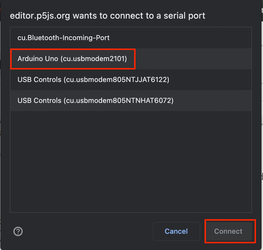
What You Should See
- choose port

- choose Arduino

- DONE!

How to send data to Processing from Arduino
What is the Serial Communication?
Serial communication is the process of sending data one bit at a time, sequentially, over a communication channel or computer bus. Simply put, serial communication is the communication between two or more computers with binary data.
In this tutorial, we will use serial communication protocol to send data to Processing from Arduino. The Processing sketch will be controlled by the physical component, the potentiometer, which can be replaced with other sensors, buttons and etc.
Wiring
- Left pin to 5V
- Right pin to GND
- middle pin to A0
Arduino Code
This example sends the potentiometer value measured from Arduino to Processing via the serial port, you can read the data from the serial monitor.
#define potPin A0
int value;
void setup() {
Serial.begin(9600); //intailise Serial communication with 9600 baud rate
pinMode( potPin, INPUT );
}
void loop() {
value = analogRead( potPin);
Serial.println(value); //read the sensor and send the value to the Serial
delay(100); //little delay to prevent Arduino going crazy
}
Processing Code
This example used the data received from Arduino to control the degrees of rotation of a rectangle in Processing.
import processing.serial.*;
Serial myPort;
String val;
int datanum = 0; //number of data receiving from Arduino
int value1;
//int value2; //multiple data from arduino if needed
void setup() {
size(800, 800);
printArray(Serial.list()); //show all ports
String portName = Serial.list()[0];//choose the correct port
myPort = new Serial(this, portName, 9600);
myPort.bufferUntil('\n');
}
void draw() {
//map() is a important function to use here,
//it convert the raw data range from Arduino to the ideal range to use in Processing
//map(a, b, c, d, e) has 5 Parameters
//map(theVariableYouWantToMap, min.ValueOfRawData, max.ValueOfRawData, min.ValueOfIdealRange, max.ValueOfIdealRange)
//in this case the min. value from the pot is 0 and max. value is 1023.
//and I want to map the background colour from black to white, 0(black) - 255(white)
float BW = map(value1,0, 1023, 0, 255 ); //create a variable to contain the converted value
background(BW);
}
void serialEvent( Serial myPort){
val = myPort.readStringUntil('\n');
if (val != null)
{
val = trim(val);
int[] vals = int(splitTokens(val, ","));
if(vals.length >= datanum){
value1 = vals[0];
//multiple data from arduino if needed
//value2 = vals[1] ;
print(value1);
}
}
}
How to use a Bare Conductive Touch Board with Arduino
What is the Bare Conductive Touch Board?
The Bare Conductive Touch Board is a board made by Bare Conductive. The Touch Board has 12 capacitive electrodes that respond to a touch. These electrodes can be extended with conductive materials, like Electric Paint or foil. The Touch Board has on-board MP3 playback and a MIDI synthesizer. This means you can either play MP3 files or simulate a MIDI instrument by touching the electrodes.

In short, the Touch Board is a pre-built Arduino that combines the functions of play MP3 and capacitive touch sensing, but you can do more than that. If you don't have the Touch Board, you can still do the same things following the above two tutorials.
Hardware Plugin
Whenever we use an Arduino, we have to tell the Arduino IDE which Arduino board we are using, whether it is an Arduino Leonardo or Arduino Mega. So we have to do the same here, telling Arduino IDE which board we are using. In this case, the Bare Conductive Touch Board. However, you cannot find the Touch Board from Tools - Boards. We have to download and put the plugin in place.
-
Quit Arduino if you have it opened.
-
Download the Hardware Plugin here: bare-conductive-arduino-public.zip
-
Create a
hardwarefolderWindows:
Libraries/Documents/Arduino/hardwareOR
My Documents/Arduino/hardwareMac:
Documents/Arduino/hardwareLinux (Ubuntu):
Home/Arduino/hardware -
Unzip and put the folder inside the hardware folder
Now open Arduino IDE, you will see the Touch Board from Tools - Boards - Bare Conductive Boards.

Library
The MPR121 is the capacitive touch chip on the Touch Board - this library allows us to access it. The VS1053 chip is the MP3 chip on the Touch Board. It uses two libraries, one for the chip and one for the onboard micro SD card.
-
Quit Arduino if you have it opened.
-
Download the MPR121 Library here: mpr121-public.zip
-
Download the VS1053 Library here: Sparkfun-MP3-Player-Shield-Arduino-Library-master.zip
-
Go to the
librariesfolderWindows: Libraries/Documents/Arduino/libraries
OR My Documents/Arduino/libraries
Mac: Documents/Arduino/libraries
Linux (Ubuntu): Home/Arduino/libraries
-
Unzip mpr121-public.zip and find the folder
MPR121 -
Unzip Sparkfun-MP3-Player-Shield-Arduino-Library-master.zip and find the folders:
SdFatandSFEMP3Shield. -
Copy
MPR121,SdFatandSFEMP3ShieldFolder to the libraries folder
Now the software Arduino IDE is ready, you will see the libraries from Sketch - Include Library.
File naming
Files saved in the Micro SD card should be named TRACK000.mp3 through TRACK011.mp3, and the Bare Conductive Board will match the file name to the E0 to E11 pins and play the according sound files.
The Touch Board will work with any size micro SD card up to 32GB.
Make sure your new SD card is formatted as FAT32.
Wiring
No wiring is needed. But you can extend each touch point with wires or connect them to any conductive materials, e.g. fruit.
Basic Example
This basic example will play TRACK000.mp3 to TRACK011.mp3 from the SD card when the according pin is touched. Download here: touch-mp3-public.zip
Sample MP3 files
To help you get up and running quickly there are some example MP3's you can use.
Resources
How to use a Hall Effect Sensor
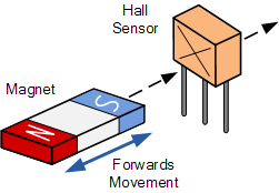
What is a Hall Effect Sensor?
The hall effect sensor is a type of magnetic sensor which can be used for detecting the strength and direction of a magnetic field produced from a permanent magnet or an electromagnet with its output varying in proportion to the strength of the magnetic field being detected.
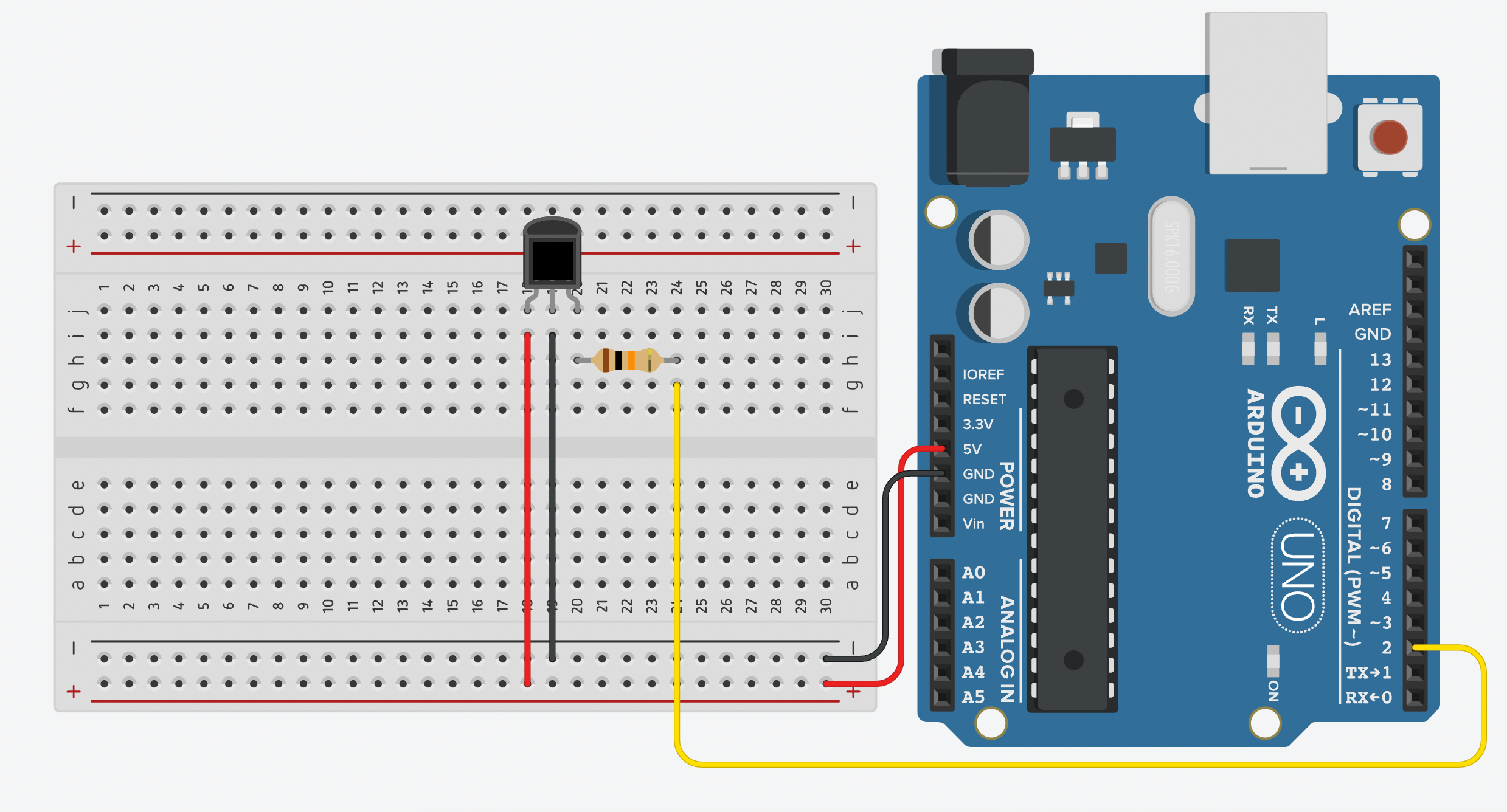
Wiring
- left to 5V (Power)
- middle to GND
- right to PIN2 via 10K resistor

Getting started
The following code uses digitalRead() to get a integer (1/0) representing the detection of magnet.
const int hallSensorPin = 2; // Hall Effect sensor connected to digital pin 2
int hallSensorState; // Variable to store the state of the sensor
void setup() {
Serial.begin(9600); // Start serial communication at 9600 baud
pinMode(hallSensorPin, INPUT); // Set the Hall Effect sensor pin as an INPUT
}
void loop() {
hallSensorState = digitalRead(hallSensorPin); // Read the state of the sensor
Serial.println(hallSensorState);
delay(100);
}
How to use a Neopixel strip
What is Neopixel?
Neopixel is a name given by Adafruit. Neopixel is addressable LEDs, meaning that they can be programmed individually. With the library created by Adafruit, you can easily program the Neopixel strip for your project. They come in different sizes and shapes and you can shorten or lengthen them flexibly. Once set up, they are very durable and efficient. They are commonly found in a lot house decorations or light installations.

Wiring
- DIN to Pin6
- +5V to 5V
- GND to GND
![]()
Library
Adafruit NeoPixel library will be used.
**Warning**
Download version 1.9.0 or below for a more stable performance.
We have a tutorial on how to install a library here.
Getting started
Once the library is installed, you can use the example code for a test run.

Before uploading the code to Arduino, one change has to be made. You should be able to find the below lines in the code.
// How many NeoPixels are attached to the Arduino?
#define LED_COUNT 60
You have to make sure how many pixels are attached to the Arduino. For example, if you are using this Neopixel stick with 8 pixels, then you have to change 60 to 8.

// How many NeoPixels are attached to the Arduino?
#define LED_COUNT 8
You should see your Neopixel beamming up right now.
How to use a PIR sensor
What is a PIR sensor?
PIR stands for Passive Infra Red and therefore a PIR sensor can etect movement of objects that radiate IR light (like human bodies). It is very commonly used for the security systems.
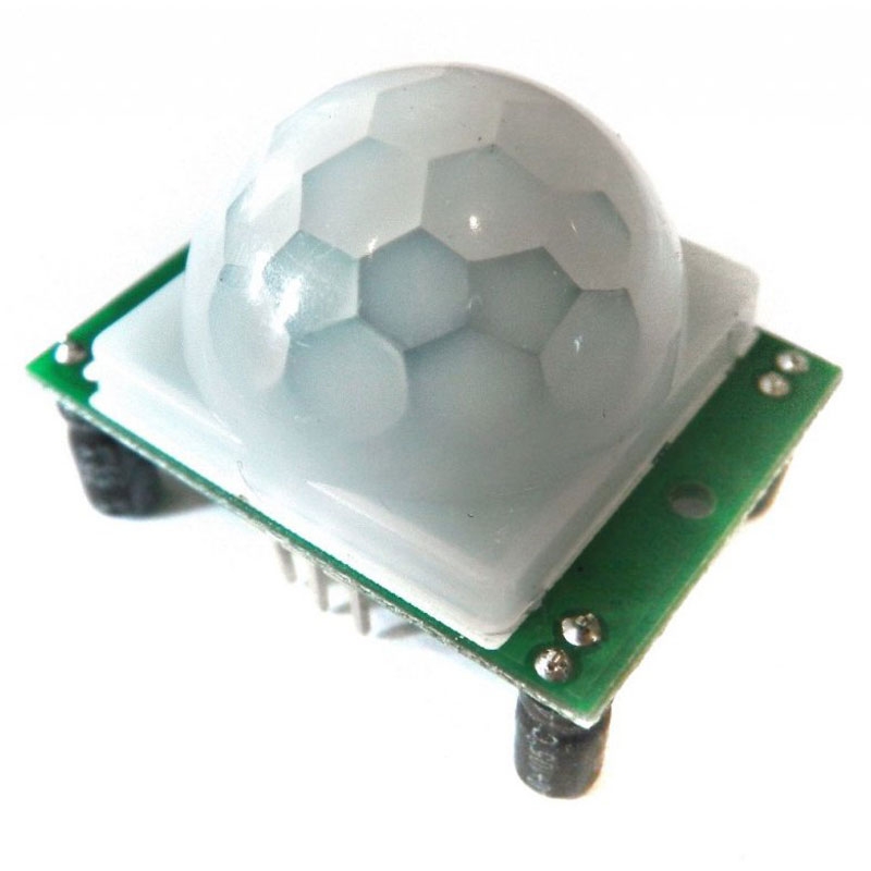
The HC-SR501’s infrared imaging sensor is an efficient, inexpensive and adjustable module for detecting motion in the environment. The small size and physical design of this module allow you to easily use it in your project.
The output of PIR motion detection sensor can be connected directly to one of the Arduino (or any microcontroller) digital pins. If any motion is detected by the sensor, this pin value will be set to “1”. The two potentiometers on the board allow you to adjust the sensitivity and delay time after detecting a movement.
Wiring
- Singal to Pin 3
- Power to 5V
- GND to GND

Getting started
int ledPin = 13; // LED
int pirPin = 3; // PIR Out pin
int pirStat = 0; // PIR status
void setup() {
pinMode(ledPin, OUTPUT);
pinMode(pirPin, INPUT);
Serial.begin(9600);
}
void loop(){
pirStat = digitalRead(pirPin);
if (pirStat == HIGH) { // if motion detected
digitalWrite(ledPin, HIGH); // turn LED ON
Serial.println("Hey I got you!!!");
}
else {
digitalWrite(ledPin, LOW); // turn LED OFF if we have no motion
}
}
How to use a relay module
What is relay?
A relay is a switch that opens or closes electrical circuits when activated by a signal between low-powered digital electronics and high-powered devices. It is handy when the thing you want to control requires higher power (voltage/current) than the microcontroller can give. Arduino can only give max. 5V and 40 mA. In this tutorial, I will use a water pump and a 1-channel 5V relay module as an example, but it can be applied to a lot of other things as well, such as lights and actuators. The relay module may vary from model to model, and they have their own maximum voltage and current ratings and power requirements, so please refer to the datasheet of the one you have.
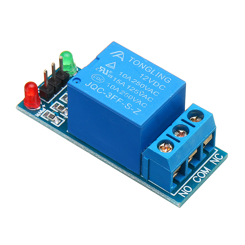
Relay module has different models providing 1/2/4/6/8 channel(s). An 8-channel relay module means it can control 8 devices. In this tutorial, I will be only using a 1 channel relay to control one water pump.
Labels on a Relay Module
- VCC/
+- Voltage, power for the module, depends on the module's need - GND/
-- Ground, power for the module, from the microcontroller's GND - IN/SIG - input/ signal, microcontroller's digital output pin
- COM - Common, Connect to the shared wire of the external power supply
You just need to use one of these.
- NO - Normally Open, Connect to the device’s positive terminal
- NC - Normally Closed, Connect to the device’s positive terminal
Open and Closed here means where the circuit is open or closed. An open circuit is off and a closed circuit is on. When a circuit is normally open, it means the device is by default off and will only turn on when it receives a HIGH/1/TRUE signal from the microcontroller. Vice versa, when a circuit is normally closed, it means the device is by default on and will only turn off when it receives a HIGH/1/TRUE signal from the microcontroller
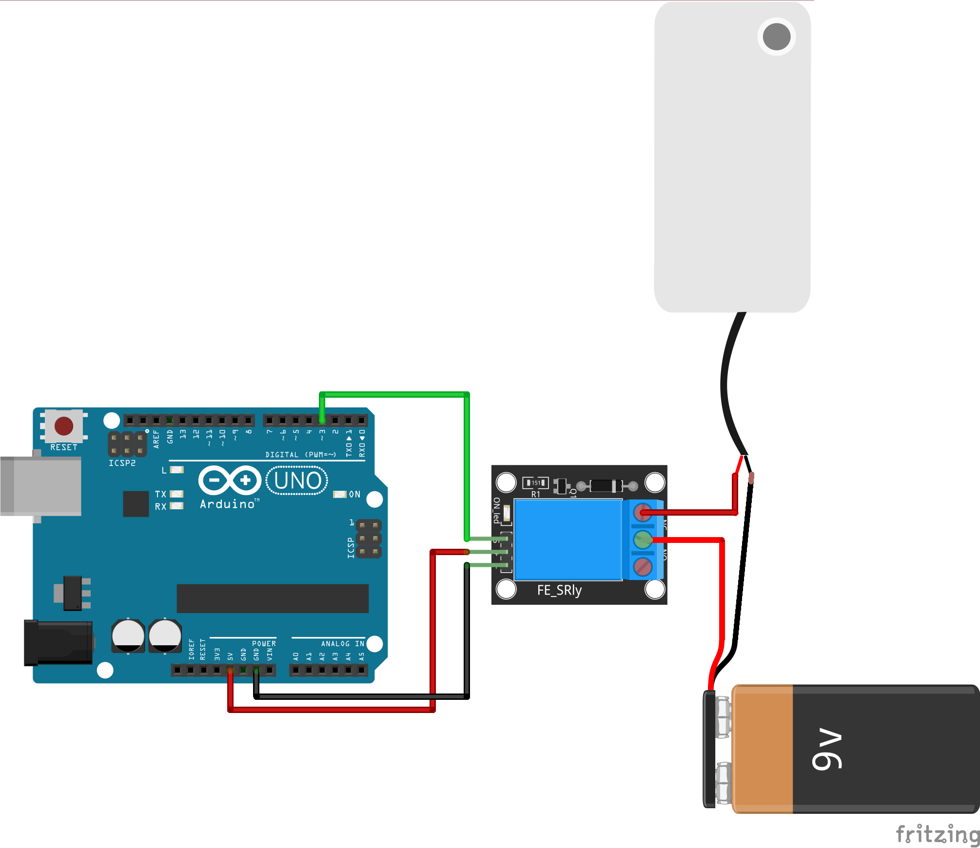
Wiring
- VCC/
+- 5V - GND/
-- GND - IN/SIG - pin 3
- NO - red(+) wire of the water pump
- COM - red(+) wire of battery
- connect the black(-) wire of the water pump and black(-) wire of battery together
Getting started
The following is a simple code that will make the water pump turn on for 1 second and off for 1 second.
const int RELAY_PIN = 3; // the Arduino pin, which connects to the IN pin of relay
// the setup function runs once when you press reset or power the board
void setup() {
// initialize digital pin as an output.
pinMode(RELAY_PIN, OUTPUT);
}
// the loop function runs over and over again forever
void loop() {
digitalWrite(RELAY_PIN, HIGH); //turn on
delay(1000);
digitalWrite(RELAY_PIN, LOW); //turn off
delay(1000);
}
How to use a rotary encoder
What is a rotary encoder?
A rotary encoder is an electromechanical device that converts the angular position or motion of a rotating shaft into electrical signals. These signals can be processed to determine rotational direction, position, and speed, making rotary encoders a key component in many types of control systems.
Wiring
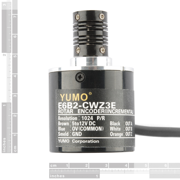 Different models of rotary encoders will have different colour codes. I am using an Incremental Rotary Encoder, YUMO E6B2-CWZ3E, the colours referred to below will only apply to this model.
There are four wires:
- Common (Blue) - GND
- Voltage (Brown) - 5V
- A switch (Black) - 2
- B switch ( White ) - 3
Getting started
The encoder produces pulses on the A and B channels as it rotates. These pulses are 90° out of phase (quadrature), which lets you detect both the amount of rotation and the direction. By reading these pulses with interrupts (which are triggered whenever the state of A or B changes), the Arduino can keep track of how far and in which direction the encoder has moved.
Key Types of Rotary Encoders
Incremental Rotary Encoder
- Outputs: Two signals (A and B channels) are generated as the shaft rotates, and these signals are in quadrature (90° out of phase).
- Working Principle: The encoder produces pulses as the shaft rotates. By counting these pulses, you can determine the angle or the distance travelled. The direction of rotation is determined by the relative timing of the A and B pulses.
- Applications: Motor control, robotics, CNC machines, etc.
- Endless rotation: They can rotate endlessly without resetting, but they only provide relative position information.
Here’s a simple visual explanation of how an incremental rotary encoder works:
A Signal: __|‾|__|‾|__|‾|__|‾|__|‾|
B Signal: _|‾|__|‾|__|‾|__|‾|__|‾|_
← Rotate CW ← ← Rotate CCW ←
When the shaft rotates, the A and B signals switch between high and low states. By detecting which signal changes first, you can determine the direction of rotation. Each pulse counts a step, which is related to the angular movement of the shaft.
Absolute Rotary Encoder
- Outputs: A unique signal (digital or analog) for each specific position of the shaft.
- Working Principle: Absolute encoders generate a unique code or position value for every possible shaft angle. This allows you to always know the exact position, even after power is cycled.
- Applications: Industrial automation, robotics, and anywhere precise positional feedback is needed.
- Single-turn vs. Multi-turn: Single-turn encoders measure the position within a single rotation, while multi-turn encoders also keep track of the number of rotations.
Basic Example
In this basic example, the encoder outputs the value as a positive or negative number from its starting position.
// Pin definitions
const int encoderPinA = 2;
const int encoderPinB = 3;
// Variables to store current and previous states of the encoder
volatile long encoderValue = 0;
volatile int lastEncoded = 0;
void setup() {
// Setup the encoder pins as inputs
pinMode(encoderPinA, INPUT);
pinMode(encoderPinB, INPUT);
// Enable pullup resistors on the encoder pins
digitalWrite(encoderPinA, HIGH);
digitalWrite(encoderPinB, HIGH);
// Attach interrupt to the encoder pins
attachInterrupt(digitalPinToInterrupt(encoderPinA), updateEncoder, CHANGE);
attachInterrupt(digitalPinToInterrupt(encoderPinB), updateEncoder, CHANGE);
Serial.begin(9600);
}
void loop() {
// Print the encoder value (step count)
Serial.print("Encoder Value: ");
Serial.println(encoderValue);
delay(100); // Adjust for your needs
}
void updateEncoder() {
// Read the encoder pins
int MSB = digitalRead(encoderPinA); // MSB = most significant bit
int LSB = digitalRead(encoderPinB); // LSB = least significant bit
int encoded = (MSB << 1) | LSB; // Combine A and B into a single value
int sum = (lastEncoded << 2) | encoded; // Combine previous and current values
// Determine the direction of rotation
if (sum == 0b1101 || sum == 0b0100 || sum == 0b0010 || sum == 0b1011) {
encoderValue++; // Clockwise
} else if (sum == 0b1110 || sum == 0b0111 || sum == 0b0001 || sum == 0b1000) {
encoderValue--; // Counter-clockwise
}
lastEncoded = encoded; // Store the current state for the next loop
}
How to use DFPlayer mini to play MP3
What is a DFPlayer?
11/2024 Update
A new library added below.
For people trying to avoid delay(), please use the DFPlayerMini_Fast library instead.
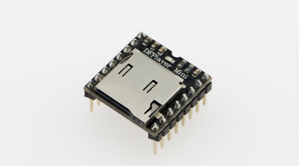
The DFPlayer Mini MP3 Player For Arduino is a small and low-priced MP3 module with a simplified output directly to the speaker. The module can be used as a stand-alone module with an attached battery, speaker and push buttons or used in combination with an Arduino UNO or any other with RX/TX capabilities. Know More
Wiring
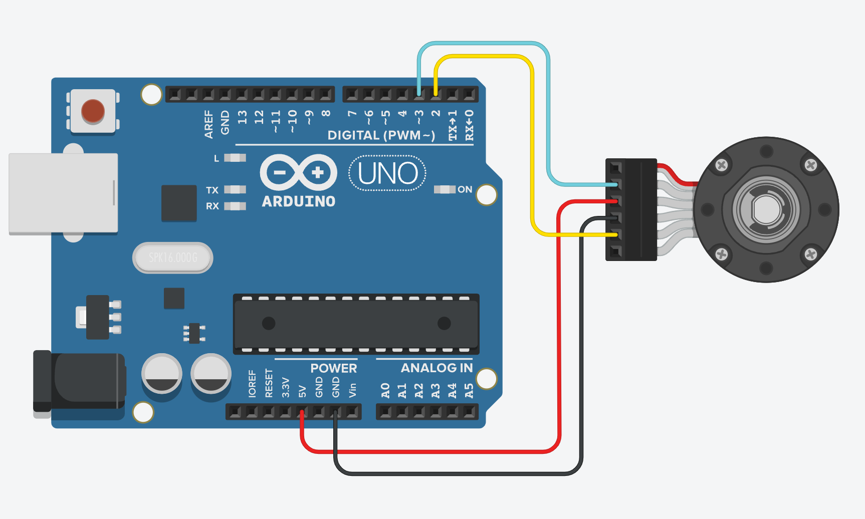
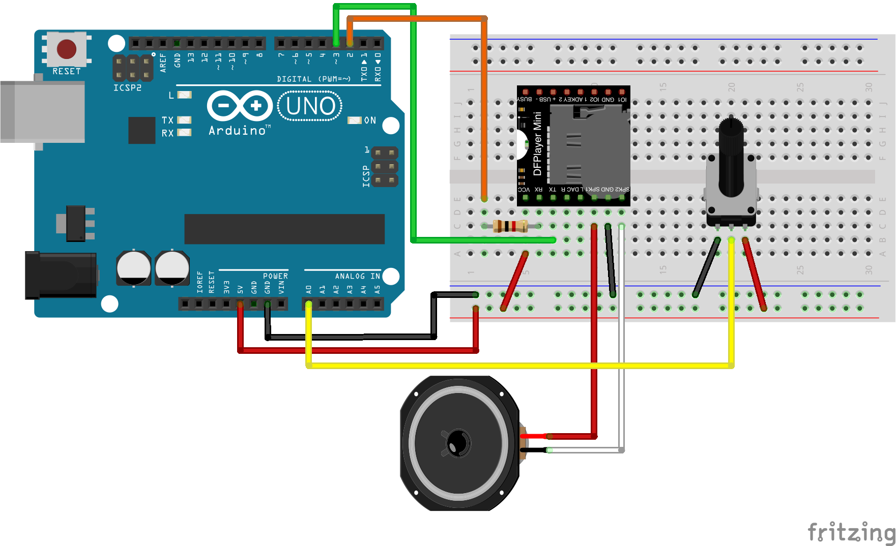
Wiring up the sensor is quite complex, the pins are not labelled so you will have to refer to the pinout.
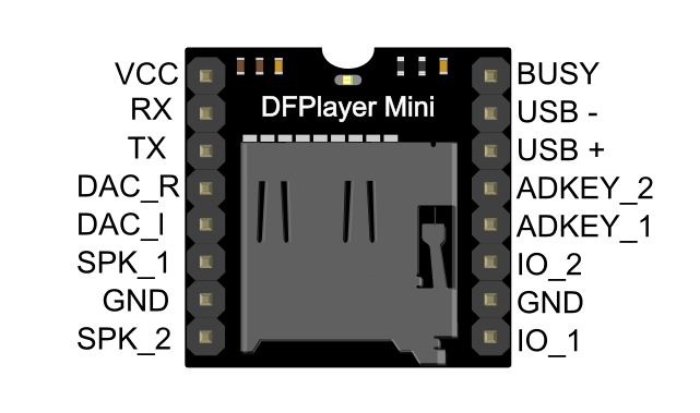
DFplayer Mini Wiring
- VCC to 5V (Power)
- RX to D2 via 1K resistor
- TX to D3
- SPK_1 to Speaker(+) red wire
- GND to GND (Ground)
- SPK_2 to Speaker(-) black wire
potentiometer Wiring
- right pin to 5V (Power)
- middle pin to A0 (Signal)
- left pin to GND (Ground)

File handling
The order you copy the mp3 onto the micro SD card will affect the order mp3 played, which means the play(1) function will play the first mp3 copied into the micro SD card.
MAC User Attention!
If you are using Mac OS X to copy the mp3, the file system will automatically add hidden files like: "._0001.mp3" for index, which this module will handle as valid mp3 files.
It is really annoying. To remove them, follow the below steps:
- Finder - Go to your USB drive
- Press
Shift+Command+.to reveal all hidden files - Select all
.XXXXXXfiles and directories and delete - Empty Bin
- Eject your USB drive
Library
DFRobotDFPlayerMini library will be used for this module. We have a tutorial on how to install a library here.
Get Started
In this example, we are using the potentiometer to control two audios. It will play the first audio when the potentiometer turns to the right and play the second when it turns to the left.
DF layer will not initiate!
If you didn't put in the SD card, or have no MP3 files in the SD card, the module will not work. Make sure you are using .mp3, not .wav or any other audio formats.
#include "SoftwareSerial.h"
#include "DFRobotDFPlayerMini.h"
// Use pins 2 and 3 to communicate with DFPlayer Mini
static const uint8_t PIN_MP3_TX = 2; // Connects to module's RX
static const uint8_t PIN_MP3_RX = 3; // Connects to module's TX
SoftwareSerial softwareSerial(PIN_MP3_RX, PIN_MP3_TX);
const int pot = A0;
int potValue = 0;
// Create the Player object
DFRobotDFPlayerMini player;
void setup() {
pinMode(pot, INPUT);
// Init USB serial port for debugging
Serial.begin(9600);
// Init serial port for DFPlayer Mini
softwareSerial.begin(9600);
// Start communication with DFPlayer Mini
if (player.begin(softwareSerial)) {
Serial.println("OK");
// Set volume to maximum (0 to 30).
player.volume(30);
} else {
Serial.println("Connecting to DFPlayer Mini failed!");
}
}
void loop() {
potValue = analogRead(pot);
if(potValue > 500 ){
static unsigned long timer = millis();
if (millis() - timer > 2000) { //2000 is the duration of the audio(1)
timer = millis();
//(2) is the 2rd file in the sd card, the order = the order you copied the file to it
player.play(2);
}
}else {
static unsigned long timer = millis();
if (millis() - timer > 3000) { //3000 is the duration of the audio(2)
timer = millis();
player.play(1);
}
}
}
Better Library
Since the official library uses delay() in the code, it can be problematic when the code is used with other components or sensors.
DFRobotDFPlayerMini_Fast library will be used for this module. You will need to do a manual install for this library. FireTimer library is also needed.
We have a tutorial on how to install a library here.
Example code
The wiring will be the same as above. For further details of this library API, please visit their github page.
#include <DFPlayerMini_Fast.h>
#include <SoftwareSerial.h>
SoftwareSerial mySerial(3, 2); // RX, TX
DFPlayerMini_Fast myMP3;
void setup()
{
Serial.begin(115200);
mySerial.begin(9600);
myMP3.begin(mySerial, true);
delay(1000);
Serial.println("Setting volume to max");
myMP3.volume(30);
Serial.println("Looping track 1");
myMP3.loop(1);
}
void loop()
{
//do nothing
}
How to use Grove Serial Bluetooth v3.0
What is Grove Serial Bluetooth v3.0
Grove - Serial Bluetooth is an easy-to-use module compatible with the existing Grove Base Shield, and designed for transparent wireless serial connection setup. In this tutorial, we will be using two Grove Serial Bluetooth modules and two Arduino to perform a wireless communication.
You can read more about this component here.
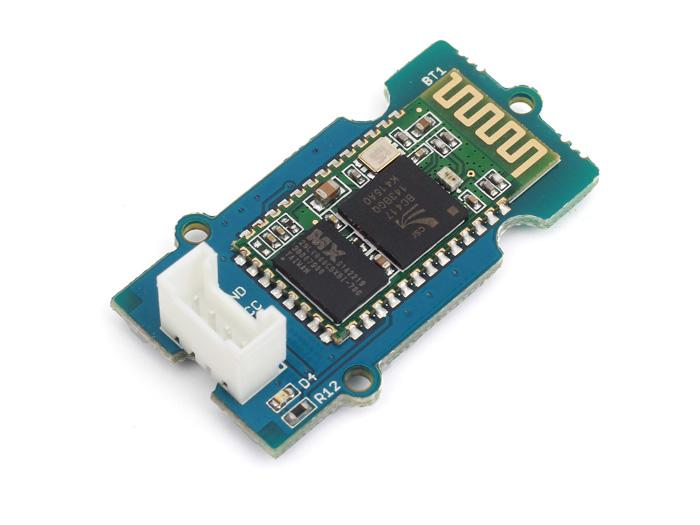
Wiring (Master - Sending data)
Interrupt Pins for RX/TX
In this tutorial, I am using an UNO which has pin 2 & 3 as the interrupts pins. Check the model you are using and change the pins accordingly.
- VCC (Red) to 5V
- GND (Black) to GND
- RX (White) to pin 3 (Arduino TX)
- TX (Yellow) to pin 2 (Arduino RX)
- Button to GND
- Button to pin 13
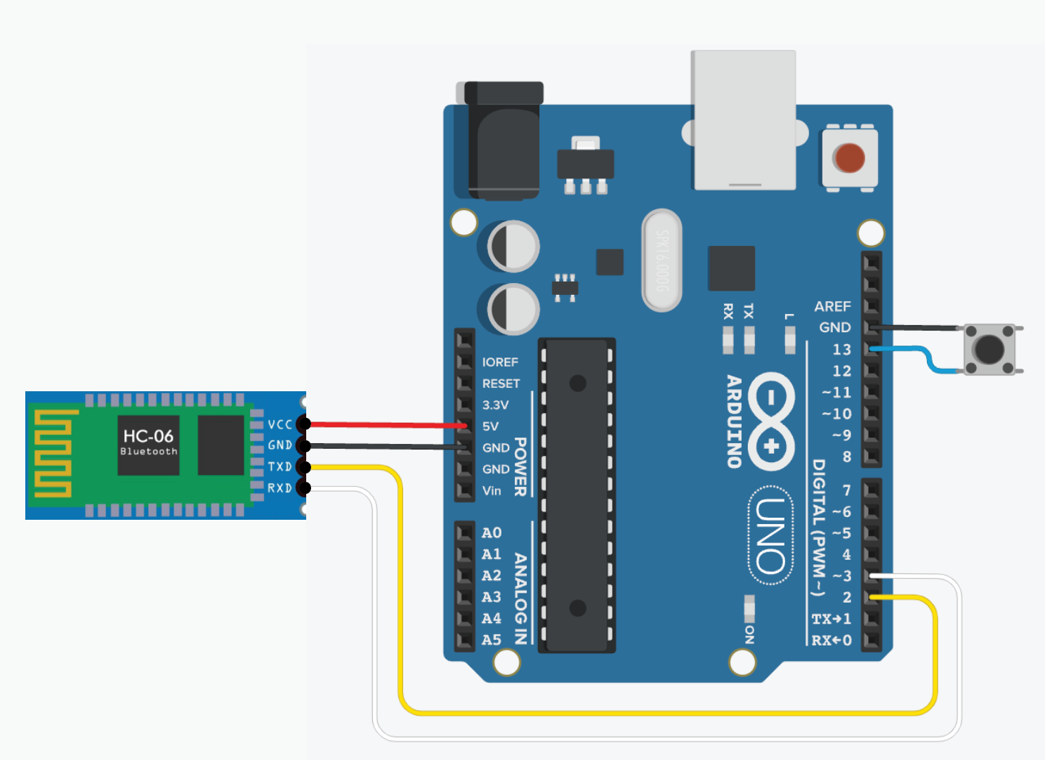
Wiring (Slave - Receving data)
- VCC (Red) to 5V
- GND (Black) to GND
- RX (White) to pin 3 (Arduino TX)
- TX (Yellow) to pin 2 (Arduino RX)
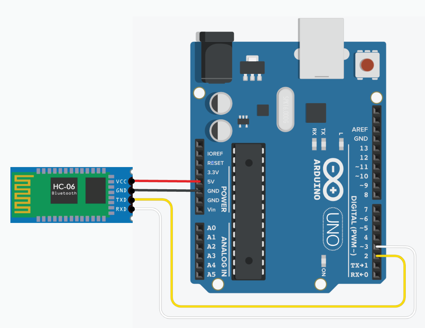
Code - Master
This code reads the signal from the button and sends it to the Slave Arduino.
/*
* FM.h
* A library for SeeedStudio Grove FM
*
* Copyright (c) 2012 seeed technology inc.
* Website : www.seeed.cc
* Author : Steve Chang
* Create Time: JULY 2014
* Change Log : Modified by loovee 2013-10-29 , Modified by jacob yan 2014-7-29
* The MIT License (MIT)
*
* Permission is hereby granted, free of charge, to any person obtaining a copy
* of this software and associated documentation files (the "Software"), to deal
* in the Software without restriction, including without limitation the rights
* to use, copy, modify, merge, publish, distribute, sublicense, and/or sell
* copies of the Software, and to permit persons to whom the Software is
* furnished to do so, subject to the following conditions:
*
* The above copyright notice and this permission notice shall be included in
* all copies or substantial portions of the Software.
*
* THE SOFTWARE IS PROVIDED "AS IS", WITHOUT WARRANTY OF ANY KIND, EXPRESS OR
* IMPLIED, INCLUDING BUT NOT LIMITED TO THE WARRANTIES OF MERCHANTABILITY,
* FITNESS FOR A PARTICULAR PURPOSE AND NONINFRINGEMENT. IN NO EVENT SHALL THE
* AUTHORS OR COPYRIGHT HOLDERS BE LIABLE FOR ANY CLAIM, DAMAGES OR OTHER
* LIABILITY, WHETHER IN AN ACTION OF CONTRACT, TORT OR OTHERWISE, ARISING FROM,
* OUT OF OR IN CONNECTION WITH THE SOFTWARE OR THE USE OR OTHER DEALINGS IN
* THE SOFTWARE.
*/
#include <SoftwareSerial.h> // Software Serial Port
#define RxD 2
#define TxD 3
#define PINBUTTON 13 // pin of button
#define DEBUG_ENABLED 1
SoftwareSerial blueToothSerial(RxD,TxD);
void setup()
{
Serial.begin(9600);
pinMode(RxD, INPUT);
pinMode(TxD, OUTPUT);
pinMode(PINBUTTON, INPUT_PULLUP);
setupBlueToothConnection();
//wait 1s and flush the serial buffer
delay(1000);
Serial.flush();
blueToothSerial.flush();
}
void loop()
{
static unsigned char state = 1; // led off
//Serial.println(digitalRead(PINBUTTON));
if(digitalRead(PINBUTTON))
{
//state = 1-state;
Serial.println("button on");
blueToothSerial.print(state);
delay(10);
while(digitalRead(PINBUTTON)) // until button release
{
delay(10);
}
Serial.println("button off");
}
}
/***************************************************************************
* Function Name: setupBlueToothConnection
* Description: initilizing bluetooth connction
* Parameters:
* Return:
***************************************************************************/
void setupBlueToothConnection()
{
blueToothSerial.begin(9600);
blueToothSerial.print("AT");
delay(400);
blueToothSerial.print("AT+DEFAULT"); // Restore all setup value to factory setup
delay(2000);
blueToothSerial.print("AT+NAMESeeedMaster"); // set the bluetooth name as "SeeedMaster" ,the length of bluetooth name must less than 12 characters.
delay(400);
blueToothSerial.print("AT+ROLEM"); // set the bluetooth work in slave mode
delay(400);
blueToothSerial.print("AT+AUTH1");
delay(400);
blueToothSerial.print("AT+CLEAR"); // Clear connected device mac address
delay(400);
blueToothSerial.flush();
}
Code - Slave
/*
* FM.h
* A library for SeeedStudio Grove FM
*
* Copyright (c) 2012 seeed technology inc.
* Website : www.seeed.cc
* Author : Steve Chang
* Create Time: JULY 2014
* Change Log : Modified by loovee 2013-10-29 , Modified by jacob yan 2014-7-29
* The MIT License (MIT)
*
* Permission is hereby granted, free of charge, to any person obtaining a copy
* of this software and associated documentation files (the "Software"), to deal
* in the Software without restriction, including without limitation the rights
* to use, copy, modify, merge, publish, distribute, sublicense, and/or sell
* copies of the Software, and to permit persons to whom the Software is
* furnished to do so, subject to the following conditions:
*
* The above copyright notice and this permission notice shall be included in
* all copies or substantial portions of the Software.
*
* THE SOFTWARE IS PROVIDED "AS IS", WITHOUT WARRANTY OF ANY KIND, EXPRESS OR
* IMPLIED, INCLUDING BUT NOT LIMITED TO THE WARRANTIES OF MERCHANTABILITY,
* FITNESS FOR A PARTICULAR PURPOSE AND NONINFRINGEMENT. IN NO EVENT SHALL THE
* AUTHORS OR COPYRIGHT HOLDERS BE LIABLE FOR ANY CLAIM, DAMAGES OR OTHER
* LIABILITY, WHETHER IN AN ACTION OF CONTRACT, TORT OR OTHERWISE, ARISING FROM,
* OUT OF OR IN CONNECTION WITH THE SOFTWARE OR THE USE OR OTHER DEALINGS IN
* THE SOFTWARE.
*/
#include <SoftwareSerial.h> //Software Serial Port
#define RxD 2
#define TxD 3
#define PINLED 13
#define LEDON() digitalWrite(PINLED, HIGH)
#define LEDOFF() digitalWrite(PINLED, LOW)
#define DEBUG_ENABLED 1
SoftwareSerial blueToothSerial(RxD,TxD);
void setup()
{
Serial.begin(9600);
pinMode(RxD, INPUT);
pinMode(TxD, OUTPUT);
pinMode(PINLED, OUTPUT);
LEDOFF();
setupBlueToothConnection();
}
void loop()
{
char recvChar;
while(1)
{
if(blueToothSerial.available())
{//check if there's any data sent from the remote bluetooth shield
recvChar = blueToothSerial.read();
Serial.print(recvChar);
if(recvChar == '1')
{
LEDON();
}
else if(recvChar == '0')
{
LEDOFF();
}
}
}
}
/***************************************************************************
* Function Name: setupBlueToothConnection
* Description: initilizing bluetooth connction
* Parameters:
* Return:
***************************************************************************/
void setupBlueToothConnection()
{
blueToothSerial.begin(9600);
blueToothSerial.print("AT");
delay(400);
blueToothSerial.print("AT+DEFAULT"); // Restore all setup value to factory setup
delay(2000);
blueToothSerial.print("AT+NAMESeeedBTSlave"); // set the bluetooth name as "SeeedBTSlave" ,the length of bluetooth name must less than 12 characters.
delay(400);
blueToothSerial.print("AT+PIN0000"); // set the pair code to connect
delay(400);
blueToothSerial.print("AT+AUTH1"); //
delay(400);
blueToothSerial.flush();
}
Connection
After uploading both codes to both Arduinos, reset them simultaneously. The LEDs on the modules will be flashing and wait until they stay on, then they are connected.
You may need to repeat a couple of times to get them connected, it's all about patience.
How to use MatrixPortal M4
What is MatrixPortal M4
The MatrixPortal M4 is a development board created by Adafruit designed to control RGB LED matrices. It is equipped with an ATSAMD51 microcontroller (Cortex M4) and has built-in Wi-Fi support thanks to the ESP32 coprocessor.
Here are some key features of the MatrixPortal M4:
- Microcontroller: ATSAMD51, Cortex M4 processor running at 120 MHz.
- Coprocessor: ESP32 handles Wi-Fi and network communication.
- Memory: 512KB of RAM, 8MB of QSPI flash storage.
- Matrix Control: Dedicated connectors for RGB LED matrices (HUB75 interface), allowing direct control without needing additional hardware.
- Power: Can be powered via USB-C or through the matrix’s power supply.
- Programming: Supports programming via CircuitPython and Arduino IDE.
- Wi-Fi Connectivity: Useful for IoT projects that require network connectivity, such as weather stations, stock tickers, or message boards.
It’s great for building projects that involve large, colourful LED displays, such as scrolling text, interactive dashboards, or internet-connected signs. In this tutorial, we will use CircuitPython to program a 64X32 matrix as CircuitPython libraries make it easier to display images, animations, text, etc than Arduino IDE.
You can read more about this component here.
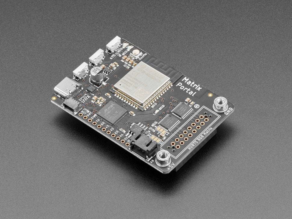
Wiring
There is no wiring needed for basic setup, it's literally plug and play. Please refer to this page to see how to set it up.
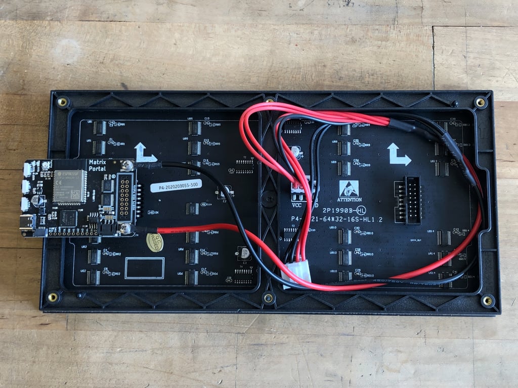
Using a 64X64 Matrix
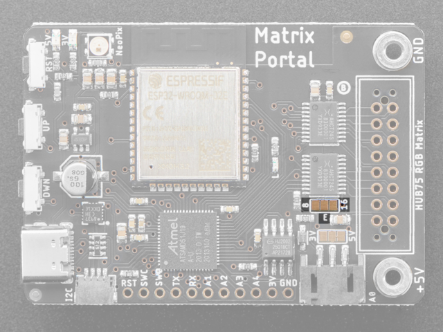
Ask a Technician first!
If you are using a MatrixPortal M4 borrowed from us, please do not do this step yourself, ask a technician for help instead.
This jumper is used for use with 64x64 matrices. You can close the jumper by using your soldering iron to melt a blob of solder on the bottom solder jumper so the middle pad is 'shorted' to 8 as below.
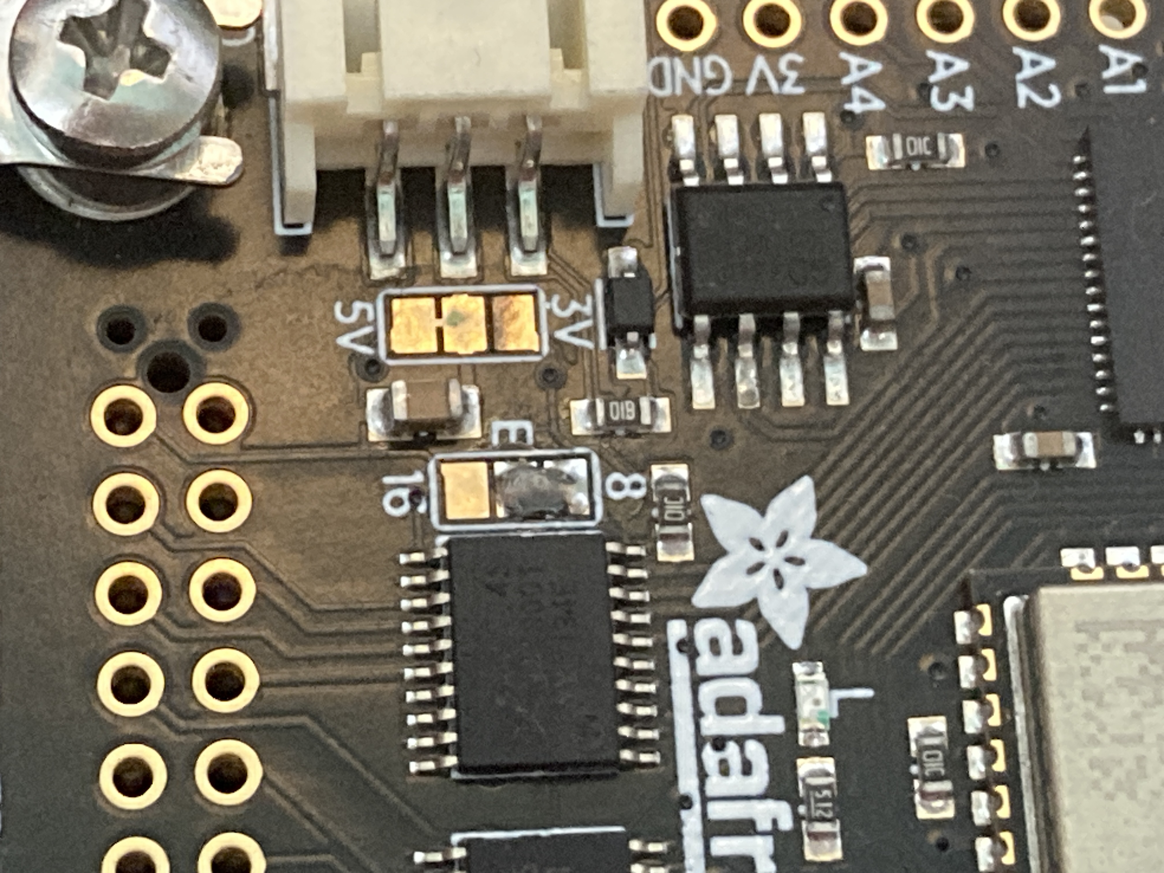
You can read more about Address E Line Jumper here.
Install CircuitPython
CircuitPython and libraries versions
In this tutorial, we are using CircuitPython 9.0.5 (11/10/2024), all libraries and code used are compatible with this version. Please double-check the latest version of CircuitPython you have installed and use updated and compatible libraries.
CircuitPython is an open-source programming language designed for microcontrollers. It's a beginner-friendly version of Python developed by Adafruit, optimized for hardware projects like controlling sensors, displays, and other electronics.
1. Download CircuitPython
Download the latest version for MatrixPortal UF2 file for your board here.
2. Put the Board into Bootloader Mode
To install CircuitPython, you need to place the board into bootloader mode.
- Press the reset button on your board twice quickly.
- The board’s LED will change to a different colour (usually pulsing red or green)
- A new USB drive will appear on your computer named something like "BOOT".
3. Copy the CircuitPython UF2 File
- Drag and drop the downloaded UF2 file onto the new drive.
- The board will reboot, and a new drive named CIRCUITPY will appear. This drive is where you'll place your Python code and libraries.
Libraries
- Download the libraries bundle here, choose the version you need.
- Copy the libraries you need to the
libfolder of the CIRCUITPY drive.
Common libraries you need:
- adafruit_matrixportal
- adafruit_debouncer.mpy
- adafruit_portalbase
- adafruit_esp32spi
- neopixel.mpy
- adafruit_bus_device
- adafruit_requests.mpy
- adafruit_fakerequests.mpy
- adafruit_io
- adafruit_bitmap_font
- adafruit_display_text
- adafruit_lis3dh.mpy
- adafruit_minimqtt
- adafruit_ticks.py
- adafruit_rgb_display
- adafruit_imageload
- adafruit_display_shapes
Code - Scrolling Text
# SPDX-FileCopyrightText: 2020 Jeff Epler for Adafruit Industries
#
# SPDX-License-Identifier: MIT
# This example implements a simple two line scroller using
# Adafruit_CircuitPython_Display_Text. Each line has its own color
# and it is possible to modify the example to use other fonts and non-standard
# characters.
import adafruit_display_text.label
import board
import displayio
import framebufferio
import rgbmatrix
import terminalio
from adafruit_bitmap_font import bitmap_font
from displayio import Bitmap
# If there was a display before (protomatter, LCD, or E-paper), release it so
# we can create ours
displayio.release_displays()
matrix = rgbmatrix.RGBMatrix(
width=64, bit_depth=6,
rgb_pins=[
board.MTX_R1,
board.MTX_G1,
board.MTX_B1,
board.MTX_R2,
board.MTX_G2,
board.MTX_B2
],
addr_pins=[
board.MTX_ADDRA,
board.MTX_ADDRB,
board.MTX_ADDRC,
board.MTX_ADDRD
],
clock_pin=board.MTX_CLK,
latch_pin=board.MTX_LAT,
output_enable_pin=board.MTX_OE
)
display = framebufferio.FramebufferDisplay(matrix, auto_refresh=False)
keycolour = 0X7BFF4A
# Create two lines of text to scroll. Besides changing the text, you can also
# customize the color and font (using Adafruit_CircuitPython_Bitmap_Font).
# To keep this demo simple, we just used the built-in font.
# The Y coordinates of the two lines were chosen so that they looked good
# but if you change the font you might find that other values work better.
line1 = adafruit_display_text.label.Label(
terminalio.FONT,
color=keycolour, #white
text="This is Creative Technology Hub")
line1.x = display.width
line1.y = 5
line2 = adafruit_display_text.label.Label(
terminalio.FONT,
color=0x000000,
background_color=keycolour,
background_tight = True,
text="Hello Hello Hello Hello Hello Helloooooooooo")
line2.x = display.width
line2.y = 15
line3 = adafruit_display_text.label.Label(
terminalio.FONT,
color=keycolour,
text="Stop peeking come in")
line3.x = display.width
line3.y = 26
# Put each line of text into a Group, then show that group.
g = displayio.Group()
g.append(line1)
g.append(line2)
g.append(line3)
display.root_group = g
# This function will scoot one label a pixel to the left and send it back to
# the far right if it's gone all the way off screen. This goes in a function
# because we'll do exactly the same thing with line1 and line2 below.
def scroll(line):
line.x = line.x - 1
line_width = line.bounding_box[2]
if line.x < -line_width:
line.x = display.width
# This function scrolls lines backwards. Try switching which function is
# called for line2 below!
def reverse_scroll(line):
line.x = line.x + 1
line_width = line.bounding_box[2]
if line.x >= display.width:
line.x = -line_width
# You can add more effects in this loop. For instance, maybe you want to set the
# color of each label to a different value.
while True:
scroll(line1)
#scroll(line2)
scroll(line3)
reverse_scroll(line2)
display.refresh(minimum_frames_per_second=1)
Touch sensor - with No Sensor!
What is Capacitive Touch Sensing?
Simply put, it is the touch sensing of all conductive materials including tinfoil, banana, plant, pencil drawing etc. In this tutorial, we will show you two types of Capacitive Touch Sensing: acute touch and proximity.
Library
ADCTouch will be used for acute touching. It provided the best accuracy without ANY external hardware.
CapacitiveSensor library will be used for proximity and/or acute touching. However, due to the constraint of the physical circuit, reading might be sometimes unreliable.
We have a tutorial on how to install a library here.
ADCTouch Library
This library makes use of the AVR internal wiring to get decent resolution with just a single pin.
Wiring
Wiring is super simple with 1 wire:
- jumper wire to A0, another end with a piece of tin foil

Code
#include <ADCTouch.h>
#define TOUCHPIN A0
// set the touch sensor resolution:
// higher means more stable results, at the cost of higher processing times
#define RESOLUTION 100
#define SMOOTH 100 // determine how many readings are stored for smoothing
float multiplier = 1.2; // determine when the sensor is understood as "ON"
int previousReadings[SMOOTH]; // smooth data a little: the last readings
int currentIndex = 0; // used for cycling through the array
int reading; // the latest reading
// calculate the average of the previous readings
int average(){
unsigned long sum = 0;
for(int i = 0; i < SMOOTH; i++){
sum += previousReadings[i];
}
return sum / SMOOTH;
}
void setup() {
Serial.begin(9600); // serial communication
pinMode(13,OUTPUT);
// fill the [previousReaings] array with readings
for(int i = 0; i < SMOOTH; i++){
previousReadings[i] = ADCTouch.read(TOUCHPIN, RESOLUTION);
}
}
void loop() {
reading = ADCTouch.read(TOUCHPIN, RESOLUTION); // read the sensor
Serial.println(reading);
// check if triggered
if(reading > average() * multiplier){
digitalWrite(13, HIGH);
}else{
digitalWrite(13, LOW);
previousReadings[currentIndex] = reading;
// set index for the next reading
currentIndex++;
// mnake sure [currentIndex] doesn't get out of bounds
if(currentIndex >= SMOOTH){
currentIndex = 0;
}
}
}
To use this code you will need the ADCTouch Library.
CapacitiveSensor Library
The physical setup includes a medium to high value (100K ohm - 50M ohm) resistor between the send pin and the receive (sensor) pin. The receive pin is the sensor terminal. A wire connected to this pin with a piece of foil at the end makes a good sensor.
Wiring
- 10M ohm resistor between pin2 and pin4
- 1 wire to pin2 to tinfoil

Code
#include <CapacitiveSensor.h>
CapacitiveSensor cs_4_2 = CapacitiveSensor(4,2); // 10M resistor between pins 4 & 2, pin 2 is sensor pin, add a wire and or foil if desired
void setup()
{
cs_4_2.set_CS_AutocaL_Millis(0xFFFFFFFF); // turn off autocalibrate on channel 1 - just as an example
Serial.begin(9600);
}
void loop()
{
long start = millis();
long total1 = cs_4_2.capacitiveSensor(30);
Serial.print(millis() - start); // check on performance in milliseconds
Serial.print("\t"); // tab character for debug windown spacing
Serial.println(total1); // print sensor output 1
delay(10); // arbitrary delay to limit data to serial port
}
To use this code you will need the CapacitiveSensor Library.
Making Breathing Light with LEDs
What is a LED?
LED (Light Emitting Diode) is a semiconductor light source that emits light when current flows through it. LED includes two pins, Cathode(-), aka the short leg, and Anode(+), aka the longer leg. It is one of the most common components. Making it lights up is usually the first step into physical computing but we are going to do a little bit more this time.
What is PWM pin?
Pulse-width modulation (PWM) pins are the pins that you can find on your Arduino with "~" in front of it. For example, pin D3, D5, D6, D9, D10 and D11 on Arduino UNO are PWM pins. The Arduino IDE has a built in function “analogWrite()” which can be used to generate a PWM signal. The frequency of this generated signal for most pins will be about 490Hz and we can give the value from 0-255 using this function.
- analogWrite(0) means a signal of 0% duty cycle. (turns somthing off)
- analogWrite(127) means a signal of 50% duty cycle. (turns somthing half on, e.g. dimmed light)
- analogWrite(255) means a signal of 100% duty cycle. (turns somthing on)
It can be used in controlling the brightness of LED, speed control of DC motor, controlling a servo motor or where you have to get analog output with digital means.
In this tutorial, we will use the PWM pins to control it and have it perform is breathing light. The second LED in this tutorial is optional.
Wiring
Wiring is simple, there are just 2 wires and a resistor.
- LED short pin (-) to Ground
- LED long pin (+) to PWM Digital pin (D3), via 220Ω resistor
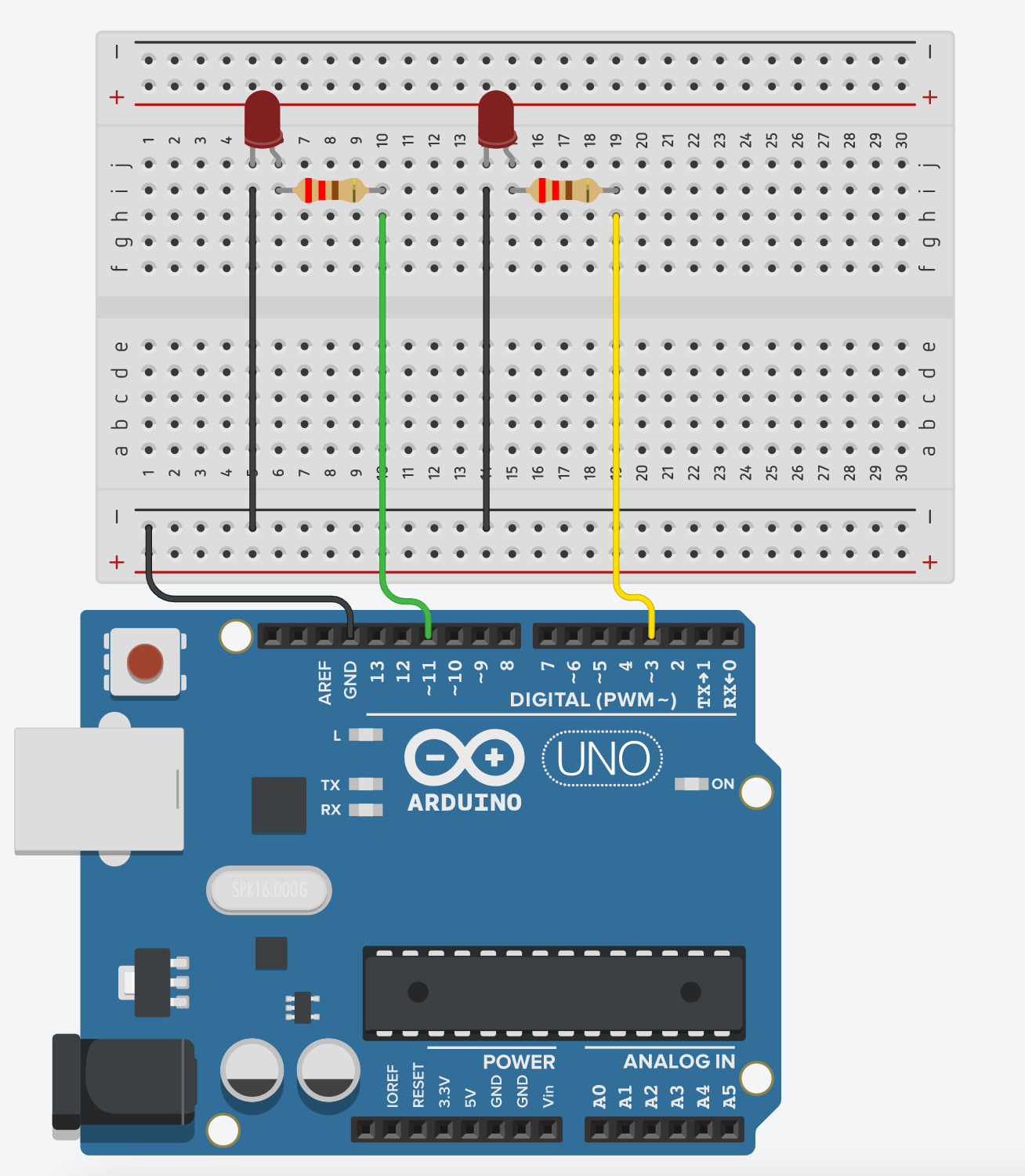
Getting started
#define led 3 //any PWM pins (~)
#define led2 11 //optional 2nd led
int brightness = 0; // how bright the LED is
int fadeAmount = 5;
void setup() {
pinMode(led, OUTPUT);
pinMode(led2, OUTPUT); //optional for 2nd led
}
void loop() {
//breathing light
analogWrite(led, brightness);
analogWrite(led2, brightness); //optional for 2nd led
brightness = brightness + fadeAmount;
if (brightness <= 0 || brightness >= 255) {
fadeAmount = -fadeAmount;
}
delay(50); //speed of the pulsing
}
Making sounds with a piezo
)# What is a piezo? 'Piezo' normally refers to an electrical component which can be used to make sound, however more broadly a piezo is a component that is susceptible to the two-way piezoelectric effect where pressing or squeezing the piezo element can create a small voltage, and vice versa a small voltage can create a small expanding/contracting movement.
Practically this means you can use a piezo to make sounds like a simple speaker, or act as a contact microphone.
In this tutorial we'll look at wiring it up to Arduino with the Tone feature to create a melody.
Wiring
Wiring is simple, there are just two wires, applying power causes the piezo to expand, just as applying power to an LED causes it to illuminate.
- Ground
- Power

Getting started
To get started quickly you can use one of the examples from the Arduino examples menu:

Powering an Arduino
How to power an Arduino
Here is some resources about powering Arduino or other electronic projects:
General
How to power an Arduino: More information here.
How to power a project:
More information here.
What Adpater:
More information here.
Portable / Battery powered
For portable projects some info on battery usage.
- How to power your Arduino with battery
- How to choose your battery
- Indepth Arduino powering guide
- Why 9V batteries are bad
Power Banks
Not all power banks are good for microcontrollers as they mostly have a safety feature which is auto-off when consumption is low. Microcontrollers often have a low-current consumption and the power bank will auto-off every a few minutes. However, there are some power banks that can support low-current charging mode/ always-on mode. These will be suitable for powering a microcontroller, e.g. Sandberg Powerbank 20000 PD65W 2xQC3.0. (We only tested this one, but other brands and models can do the same.)
Motors
There are many different types of motors available. Before deciding how to power your motor, you must know what voltage the motor is going to use and how much current your motor will need.
- Guide for powering motors with Raspberry Pi: here.
- Guide for Adafruit Motor Shield with Arduino: here.
Making a Force Sensor/ a Button with Velostat & Conductive Fabric
What is a Velostat and Conductive Fabric?
Velostat (a.k.a. Linqstat) is a thin, flexible, pressure-sensitive plastic sheet made with carbon black. It’s a piezoresistive material — its electrical resistance changes when pressure is applied.
Conductive Fabric is a textile material (woven or non-woven) with conductive threads or coatings, like silver, copper, nickel, or carbon. It conducts electricity like a wire but is soft and flexible like fabric.
Assembling the Velostat and Conductive Fabric
- You need 2 pieces of conductive fabrics and 1 piece of velostat.
- Make sure the 2 pieces of conductive fabrics are not touching each other.

- Tape them down so they are firmly in contact.

- (Optional) Using a piece of non-conductive material as the base to hold everything together, preferably something spongy.
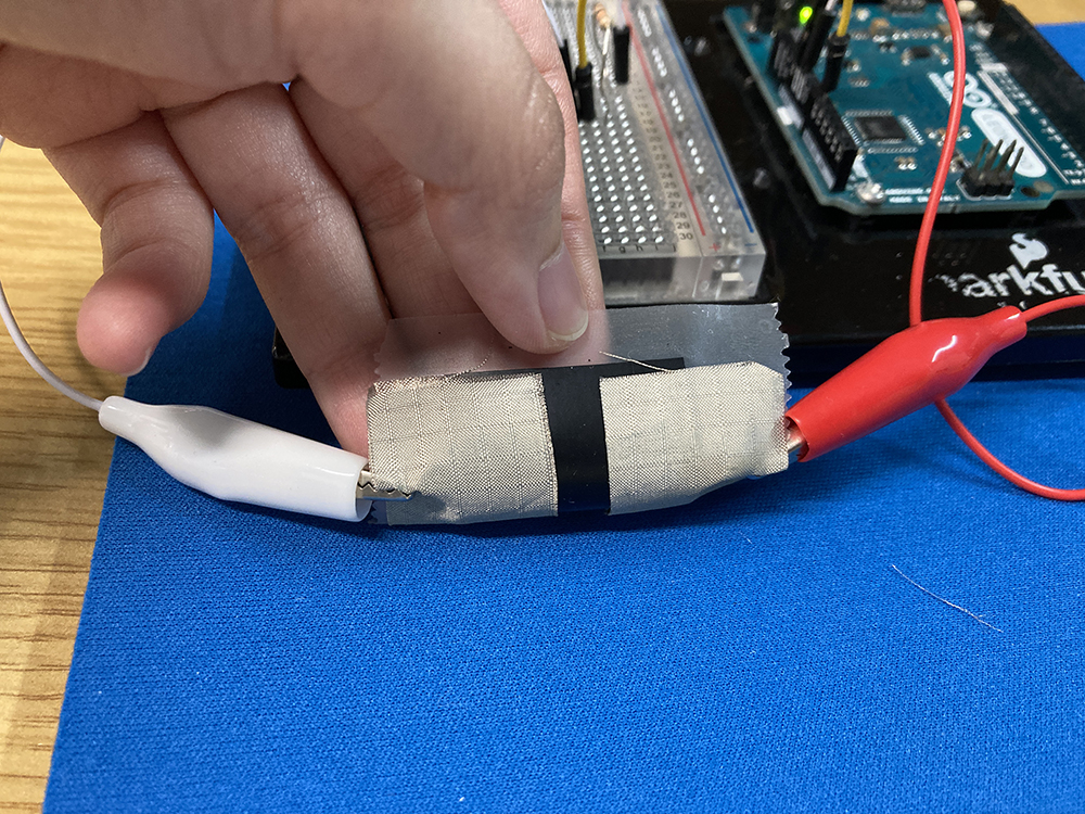
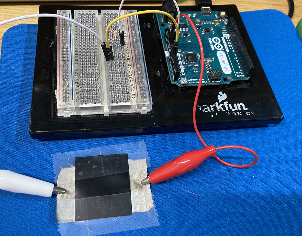
Making a Force Sensor
Wiring
Wiring up the sensor is simple, the sensor is unpolarized so it's doesn't matter which pin to 5V or GND.
- Power (one end to 5V)
- Ground (one end to GND with 10K resistor)
- Signal (GND side to A0)
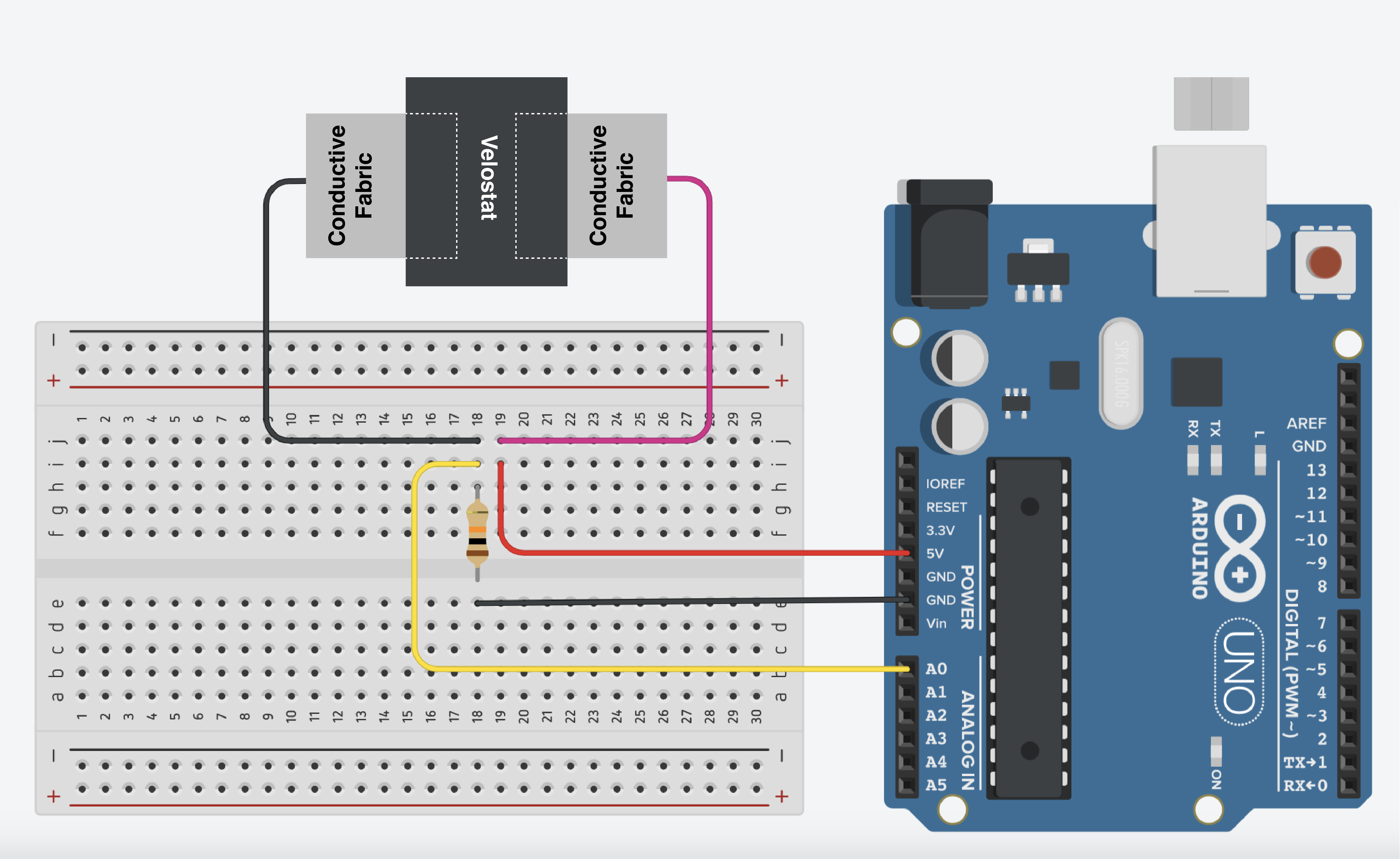
Code
This example measures the force applied to the velostat.
int sensorPin = A0;
void setup() {
Serial.begin(9600);
}
void loop() {
int sensorValue = analogRead(sensorPin); // gives analog values for the sensors
Serial.println(sensorValue);
delay (100); // change for the speed of serial monitor
}
Making a Button
Wiring
We are using a Pull-Up Resistor button set up.
- Ground (one end to GND )
- Signal (one end to A0)
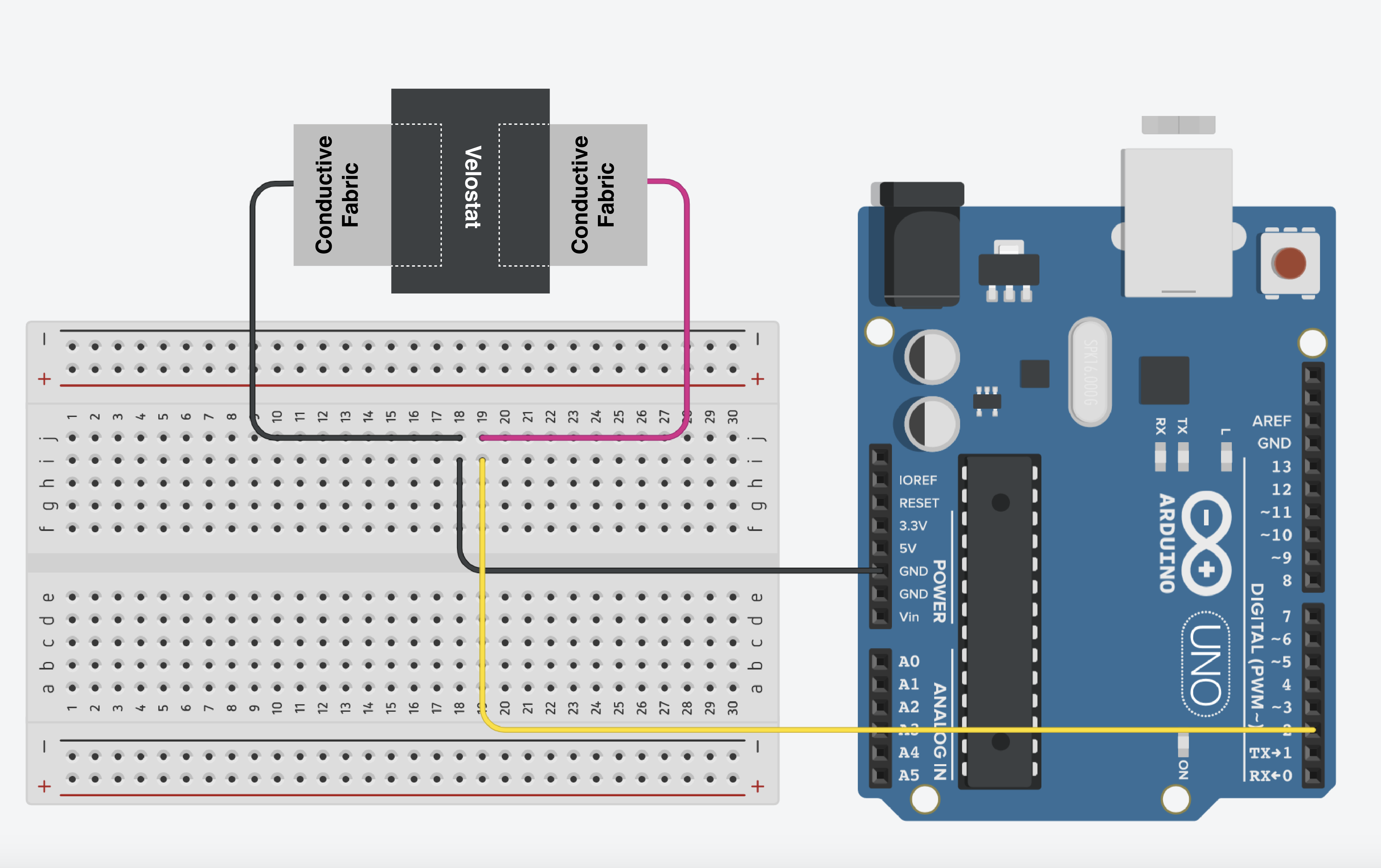
Code
This example detects if the velostat is pressed.
int buttonPin = 2;
int buttonState;
void setup() {
// put your setup code here, to run once:
Serial.begin(9600);
pinMode(buttonPin, INPUT_PULLUP);
}
void loop() {
// put your main code here, to run repeatedly:
buttonState = digitalRead(buttonPin);
Serial.println(buttonState);
delay (100); // change for the speed of serial monitor
}
Using a Force Sensor
What is a Force Sensor?
The Force Sensor senses the resistance value depending on how much it has pressed. It can sense even the slightest touch, therefore you can use it as a touch sensor as well. The difference between this and Capacitive Sensor is that the object you touched doesn't need to be conductive as it is sensing force.
It is cheap and easy to use. It provides accurate readings for physical pressure but it cannot be used for measuring weight. You can put it underneath most materials, e.g. painting, shoes etc, and it is easy to hide.
Wiring
Wiring up the sensor is simple, the sensor is unpolarized so it's doesn't matter which pin to 5V or GND.
- Power (one end to 5V)
- Ground (one end to GND with 10K resistor)
- Signal (GND side to A0)

Getting started
This example turns on the built-in LED when touched lightly.
int sensorPin = A0;
int sensorValue;
//sensor value range: 0-1023
//200 is light touch
//500 is medium touch
//800 is hard touch
int limit = 200;
void setup() {
Serial.begin(9600);
pinMode(13, OUTPUT);
}
void loop() {
sensorValue = analogRead(sensorPin);
Serial.print("Force Level: ");
Serial.println(sensorValue);
if (sensorValue > limit) {
digitalWrite(13, HIGH);
}
else {
digitalWrite(13, LOW);
}
delay(100);
}
Using a Membrane Potentiometer (SoftPot)
What is a Membrane Potentiometer?
A Membrane Potentiometer is a type of position sensor that measures displacement or angle by detecting changes in electrical resistance. It consists of a flexible membrane with resistive and conductive layers that slide against each other when pressure is applied. This alters the resistance and provides an output voltage proportional to the position.


- Thin and Flexible: Made from polymer films, they are compact and adaptable.
- Contact-Based Operation: A wiper or finger presses the membrane to register position.
- Linear or Rotary Versions: Available for linear displacement or rotational measurement.
- Durability: No mechanical wear like traditional potentiometers with sliding contacts.
- Application: Touch-sensitive controls
Wiring
Wiring up the sensor is simple, the sensor is unpolarized so it's doesn't matter which pin to 5V or GND.
- Pin1 (the one on the side of the thinner strip) to 5V
- Pin2 (middle pin) to A0 & via 10k resistor to GND
- Pin3 (the one with a small arrow) to GND

Getting started
This example turns on the built-in LED when touched lightly.
int SOFT_POT_PIN = A0;
void setup()
{
Serial.begin(9600);
pinMode(SOFT_POT_PIN, INPUT);
}
void loop()
{
int softPotPosition = analogRead(SOFT_POT_PIN);
Serial.println(softPotPosition);
delay(100);
}
Using a HC-SR04 distance sensor
What is the HC-SR04?
The HC-SR04 is a ultrasonic distance sensor, it uses ultrasound to send out a ping and measure how long the sound takes to come back, exactly like bats use to fly in the dark.
The sensor works between 2-400cm however if the ping sound is reflected away from the sensor by an a divergent (not parallel) surface, or absorbed by a soft surface like fabric there may no measurement.
There are other types of distance sensors that are more accurate for projects where needed, this is a cheap < £5 sensor, while more accurate ones are over £100.
Wiring
Wiring up the sensor is simple:
- Power (VCC to 5V)
- Ground (GND to GND)
- Echo to digital pin 12
- Trigger to digital pin 13

Getting started
To use this code you will need the HCSR04 Library by Martin Sosic. We have a tutorial on how to install a library here.
This example turns on an LED when the distance measured is less than 30cm and back off when the distance goes over 30cm.
#include <HCSR04.h>
// Initialize sensor that uses digital pins 13 and 12.
UltraSonicDistanceSensor distanceSensor(13, 12);
void setup () {
Serial.begin(9600); //initialize serial connection so that we could print values from sensor.
pinMode(13, OUTPUT);
}
void loop () {
float distance = distanceSensor.measureDistanceCm();
Serial.println(distance);
if (distance < 30 ){
digitalWrite(13, HIGH);
delay(100);
}else{
digitalWrite(13, LOW);
delay(100);
}
}
Using a Monochrome 1.3" 128x64 OLED display
What is the OLED monochrome display?
The OLED monochrome display is a small (tiny) and high-readability display. It is useful for displaying data, e.g. weather information or small graphics like what you see on Tamagotchi. For more information, please visit here.
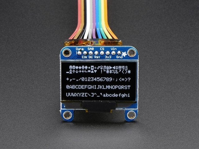
In this tutorial, we will be using Adafruit SSD1306 128 x 64 OLED with I2C communication. It can support SPI communication as well.
Display Configuration
If you have the older non-STEMMA version of the OLED, you'll need to solder the two jumpers on the back of the OLED. Both must be soldered 'closed' for I2C to work!
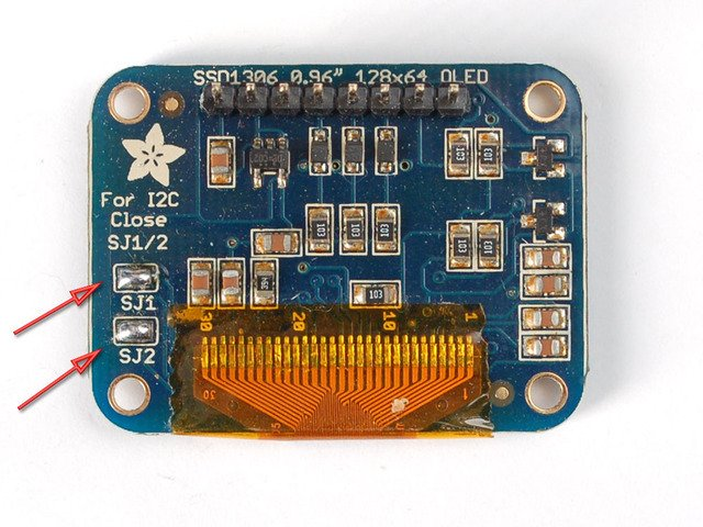
Wiring
Wiring up the sensor is simple:
- Power (VIN to 5V)
- Ground (GND to GND)
- Data to Arduino SDA pin (A5 on Uno)
- CLK to Arduino SCL pin (A4 on Uno)
Library
To use this code you will need the Adafruit_SSD1306 Library. We have a tutorial on how to install a library here.
Getting started
This code will display two bitmap images at intervals of 1 second.
#include <SPI.h>
#include <Wire.h>
#include <Adafruit_GFX.h>
#include <Adafruit_SSD1306.h>
#define SCREEN_WIDTH 128 // OLED display width, in pixels
#define SCREEN_HEIGHT 64 // OLED display height, in pixels
// Declaration for an SSD1306 display connected to I2C (SDA, SCL pins)
// The pins for I2C are defined by the Wire-library.
// On an arduino UNO: A4(SDA), A5(SCL)
// On an arduino MEGA 2560: 20(SDA), 21(SCL)
// On an arduino LEONARDO: 2(SDA), 3(SCL), ...
#define OLED_RESET 4 // Reset pin # (or -1 if sharing Arduino reset pin)
#define SCREEN_ADDRESS 0x3D ///< See datasheet for Address; 0x3D for 128x64, 0x3C for 128x32
Adafruit_SSD1306 display(SCREEN_WIDTH, SCREEN_HEIGHT, &Wire, OLED_RESET);
int numImage = 2;
int frameRate = 85; // 85 = 12fps, 67 = 15fps, 42 = 24fps
int counter = 0;
const unsigned char my_bitmap [][8192] PROGMEM = {
{
0x00, 0x00, 0x00, 0x00, 0x00, 0x00, 0x00, 0x00, 0x00, 0x00, 0x00, 0x00, 0x00, 0x00, 0x00, 0x00,
0x00, 0x00, 0x00, 0x00, 0x00, 0x00, 0x00, 0x00, 0x00, 0x00, 0x00, 0x00, 0x00, 0x00, 0x00, 0x00,
0x00, 0x00, 0x00, 0x00, 0x00, 0x00, 0x00, 0x00, 0x00, 0x00, 0x00, 0x00, 0x00, 0x00, 0x00, 0x00,
0x00, 0x00, 0x00, 0x00, 0x00, 0x00, 0x00, 0x00, 0x00, 0x00, 0x00, 0x00, 0x00, 0x00, 0x00, 0x00,
0x00, 0x00, 0x00, 0x00, 0x00, 0x00, 0x00, 0x00, 0x00, 0x00, 0x00, 0x00, 0x00, 0x00, 0x00, 0x00,
0x00, 0x00, 0x00, 0x00, 0x00, 0x00, 0x00, 0x00, 0x00, 0x00, 0x00, 0x00, 0x00, 0x00, 0x00, 0x00,
0x00, 0x00, 0x00, 0x00, 0x00, 0x00, 0x00, 0x00, 0x00, 0x00, 0x00, 0x00, 0x00, 0x00, 0x00, 0x00,
0x00, 0x00, 0x00, 0x00, 0x00, 0x00, 0x00, 0x00, 0x00, 0x00, 0x00, 0x00, 0x00, 0x00, 0x00, 0x00,
0x00, 0x00, 0x00, 0x00, 0x00, 0x00, 0x00, 0x00, 0x00, 0x7f, 0xfc, 0x00, 0x00, 0x00, 0x00, 0x00,
0x00, 0x00, 0x00, 0x00, 0x00, 0x00, 0x00, 0x00, 0x3f, 0x80, 0x03, 0x00, 0x00, 0x00, 0x00, 0x00,
0x00, 0x00, 0x00, 0x00, 0x00, 0x00, 0x00, 0x01, 0xc0, 0x00, 0x00, 0x80, 0x00, 0x00, 0x00, 0x00,
0x00, 0x00, 0x00, 0x00, 0x00, 0x00, 0x00, 0x06, 0x00, 0x00, 0x00, 0x40, 0x00, 0x00, 0x00, 0x00,
0x00, 0x00, 0x00, 0x00, 0x00, 0x00, 0x00, 0x08, 0x00, 0x00, 0x00, 0x20, 0x00, 0x00, 0x00, 0x00,
0x00, 0x00, 0x00, 0x00, 0x00, 0x00, 0x00, 0x10, 0x00, 0x00, 0x00, 0x10, 0x00, 0x00, 0x00, 0x80,
0x00, 0x00, 0x00, 0x0f, 0xe0, 0x00, 0x00, 0x20, 0x00, 0x00, 0x00, 0x08, 0x00, 0x00, 0x00, 0x80,
0x00, 0x00, 0x00, 0x30, 0x1c, 0x00, 0x00, 0x20, 0x00, 0x00, 0x00, 0x08, 0x00, 0x00, 0x00, 0x80,
0x00, 0x00, 0x00, 0x40, 0x03, 0x00, 0x00, 0x40, 0x00, 0x00, 0x00, 0x06, 0x00, 0x00, 0x00, 0x80,
0x00, 0x00, 0x00, 0x80, 0x01, 0x00, 0x00, 0x40, 0x00, 0x00, 0x00, 0x02, 0x00, 0x00, 0x01, 0x00,
0x00, 0x00, 0x01, 0x00, 0x01, 0x00, 0x00, 0x40, 0x00, 0x00, 0x00, 0x02, 0x00, 0x00, 0x01, 0x00,
0x00, 0x00, 0x06, 0x00, 0x01, 0x00, 0x00, 0x40, 0x00, 0x00, 0x00, 0x02, 0x00, 0x7e, 0x01, 0x00,
0x00, 0x00, 0x04, 0x00, 0x01, 0x00, 0x00, 0x40, 0x00, 0x00, 0x38, 0x04, 0x00, 0x81, 0x81, 0x00,
0x00, 0x00, 0x08, 0x00, 0x01, 0x00, 0x00, 0x20, 0x00, 0x01, 0xc7, 0x84, 0x03, 0x00, 0x41, 0x00,
0x00, 0x00, 0x10, 0x00, 0x01, 0x00, 0x00, 0x10, 0x00, 0x01, 0x00, 0x44, 0x04, 0x00, 0x41, 0x00,
0x00, 0x00, 0x20, 0x00, 0x01, 0x00, 0x00, 0x10, 0x00, 0x01, 0xc0, 0x38, 0x04, 0x00, 0x22, 0x00,
0x00, 0x00, 0x60, 0x00, 0x03, 0x00, 0x00, 0x08, 0x00, 0x00, 0x20, 0x20, 0x08, 0x00, 0x12, 0x00,
0x00, 0x00, 0xc0, 0x00, 0x02, 0x00, 0x00, 0x06, 0x00, 0x00, 0x19, 0xe0, 0x08, 0x00, 0x16, 0x00,
0x00, 0x00, 0x80, 0x00, 0x02, 0x00, 0x00, 0x01, 0x00, 0x00, 0x06, 0x20, 0x08, 0x00, 0x18, 0x00,
0x00, 0x00, 0x00, 0x00, 0x02, 0x00, 0x00, 0x00, 0x80, 0x00, 0x00, 0x20, 0x08, 0x00, 0x18, 0x00,
0x00, 0x00, 0x00, 0x38, 0x02, 0x00, 0xfe, 0x00, 0x60, 0x00, 0x00, 0x20, 0x08, 0x00, 0x10, 0x00,
0x00, 0x00, 0x00, 0xc6, 0x02, 0x01, 0x03, 0x00, 0x18, 0x00, 0x00, 0x20, 0x04, 0x01, 0xf0, 0x00,
0x00, 0x00, 0x01, 0x81, 0x02, 0x01, 0x01, 0x00, 0x08, 0x00, 0x00, 0x20, 0x02, 0x1e, 0x08, 0x00,
0x00, 0x00, 0x03, 0x00, 0x84, 0x02, 0x00, 0x80, 0x06, 0x00, 0x00, 0x40, 0x01, 0xe0, 0x08, 0x00,
0x00, 0x00, 0x02, 0x00, 0x44, 0x02, 0x00, 0x40, 0x01, 0x00, 0x00, 0xc0, 0x00, 0x00, 0x08, 0x00,
0x00, 0x00, 0x02, 0x00, 0x24, 0x02, 0x00, 0x60, 0x01, 0x00, 0x00, 0x80, 0x00, 0x00, 0x08, 0x00,
0x00, 0x00, 0x02, 0x00, 0x24, 0x04, 0x00, 0x20, 0x01, 0x00, 0x00, 0x80, 0x00, 0x00, 0x08, 0x00,
0x00, 0x00, 0x02, 0x00, 0x18, 0x04, 0x00, 0x20, 0x00, 0x80, 0x00, 0x80, 0x00, 0x00, 0x08, 0x00,
0x00, 0x00, 0x02, 0x00, 0x08, 0x02, 0x00, 0x20, 0x00, 0x80, 0x01, 0x00, 0x00, 0x00, 0x08, 0x00,
0x00, 0x00, 0x02, 0x00, 0x08, 0x02, 0x00, 0x20, 0x00, 0x80, 0x01, 0x00, 0x00, 0x00, 0x08, 0x00,
0x00, 0x00, 0x02, 0x00, 0x14, 0x02, 0x00, 0x40, 0x01, 0x00, 0x01, 0x00, 0x00, 0x00, 0x10, 0x00,
0x00, 0x00, 0x02, 0x00, 0x12, 0x02, 0x00, 0x40, 0x01, 0x00, 0x01, 0x00, 0x00, 0x00, 0x10, 0x00,
0x00, 0x00, 0x02, 0x00, 0x12, 0x02, 0x00, 0x40, 0x01, 0x00, 0x01, 0x00, 0x00, 0x00, 0x20, 0x00,
0x00, 0x00, 0x02, 0x00, 0x21, 0x82, 0x00, 0x80, 0x02, 0x00, 0x01, 0x00, 0x00, 0x00, 0x20, 0x00,
0x00, 0x00, 0x02, 0x00, 0x40, 0x41, 0x00, 0x80, 0x02, 0x00, 0x01, 0x00, 0x00, 0x00, 0x40, 0x00,
0x00, 0x00, 0x01, 0x00, 0x40, 0x30, 0x83, 0x00, 0x0c, 0x00, 0x01, 0x00, 0x00, 0x00, 0x80, 0x00,
0x00, 0x00, 0x00, 0x80, 0xc0, 0x0c, 0x4c, 0x00, 0x30, 0x00, 0x00, 0x80, 0x00, 0x01, 0x00, 0x00,
0x00, 0x00, 0x00, 0x61, 0x80, 0x03, 0xf0, 0x00, 0x40, 0x00, 0x00, 0x80, 0x00, 0x02, 0x00, 0x00,
0x00, 0x00, 0x00, 0x3f, 0x00, 0x00, 0x10, 0x00, 0x80, 0x00, 0x00, 0x80, 0x00, 0x02, 0x00, 0x00,
0x00, 0x00, 0x00, 0x00, 0x00, 0x00, 0x0f, 0x07, 0x00, 0x00, 0x00, 0x40, 0x00, 0x0c, 0x00, 0x00,
0x00, 0x00, 0x00, 0x00, 0x00, 0x00, 0x00, 0xf8, 0x00, 0x00, 0x00, 0x40, 0x00, 0x30, 0x00, 0x00,
0x00, 0x00, 0x00, 0x00, 0x00, 0x00, 0x00, 0x00, 0x00, 0x00, 0x00, 0x30, 0x00, 0xc0, 0x00, 0x00,
0x00, 0x00, 0x00, 0x00, 0x00, 0x00, 0x00, 0x00, 0x00, 0x00, 0x00, 0x0f, 0x83, 0x00, 0x00, 0x00,
0x00, 0x00, 0x00, 0x00, 0x00, 0x00, 0x00, 0x00, 0x00, 0x00, 0x00, 0x00, 0x7c, 0x00, 0x00, 0x00,
0x00, 0x00, 0x00, 0x00, 0x00, 0x00, 0x00, 0x00, 0x00, 0x00, 0x00, 0x00, 0x00, 0x00, 0x00, 0x00,
0x00, 0x00, 0x00, 0x00, 0x00, 0x00, 0x00, 0x00, 0x00, 0x00, 0x00, 0x00, 0x00, 0x00, 0x00, 0x00,
0x00, 0x00, 0x00, 0x00, 0x00, 0x00, 0x00, 0x00, 0x00, 0x00, 0x00, 0x00, 0x00, 0x00, 0x00, 0x00,
0x00, 0x00, 0x00, 0x00, 0x00, 0x00, 0x00, 0x00, 0x00, 0x00, 0x00, 0x00, 0x00, 0x00, 0x00, 0x00,
0x00, 0x00, 0x00, 0x00, 0x00, 0x00, 0x00, 0x00, 0x00, 0x00, 0x00, 0x00, 0x00, 0x00, 0x00, 0x00,
0x00, 0x00, 0x00, 0x00, 0x00, 0x00, 0x00, 0x00, 0x00, 0x00, 0x00, 0x00, 0x00, 0x00, 0x00, 0x00,
0x00, 0x00, 0x00, 0x00, 0x00, 0x00, 0x00, 0x00, 0x00, 0x00, 0x00, 0x00, 0x00, 0x00, 0x00, 0x00,
0x00, 0x00, 0x00, 0x00, 0x00, 0x00, 0x00, 0x00, 0x00, 0x00, 0x00, 0x00, 0x00, 0x00, 0x00, 0x00,
0x00, 0x00, 0x00, 0x00, 0x00, 0x00, 0x00, 0x00, 0x00, 0x00, 0x00, 0x00, 0x00, 0x00, 0x00, 0x00,
0x00, 0x00, 0x00, 0x00, 0x00, 0x00, 0x00, 0x00, 0x00, 0x00, 0x00, 0x00, 0x00, 0x00, 0x00, 0x00,
0x00, 0x00, 0x00, 0x00, 0x00, 0x00, 0x00, 0x00, 0x00, 0x00, 0x00, 0x00, 0x00, 0x00, 0x00, 0x00,
0x00, 0x00, 0x00, 0x00, 0x00, 0x00, 0x00, 0x00, 0x00, 0x00, 0x00, 0x00, 0x00, 0x00, 0x00, 0x00
},
{
0x00, 0x00, 0x00, 0x00, 0x00, 0x00, 0x00, 0x00, 0x00, 0x00, 0x00, 0x00, 0x00, 0x00, 0x00, 0x00,
0x00, 0x00, 0x00, 0x00, 0x00, 0x00, 0x00, 0x00, 0x00, 0x00, 0x00, 0x00, 0x00, 0x00, 0x00, 0x00,
0x00, 0x00, 0x00, 0x00, 0x00, 0x00, 0x00, 0x00, 0x00, 0x00, 0x00, 0x00, 0x00, 0x00, 0x00, 0x00,
0x00, 0x00, 0x00, 0x00, 0x00, 0x00, 0x00, 0x00, 0x00, 0x00, 0x00, 0x00, 0x00, 0x00, 0x00, 0x00,
0x00, 0x00, 0x00, 0x00, 0x00, 0x00, 0x00, 0x00, 0x00, 0x00, 0x00, 0x00, 0x00, 0x00, 0x00, 0x00,
0x00, 0x00, 0x00, 0x00, 0x00, 0x00, 0x00, 0x00, 0x00, 0x00, 0x00, 0x00, 0x00, 0x00, 0x00, 0x00,
0x00, 0x00, 0x00, 0x00, 0x00, 0x00, 0x00, 0x00, 0x00, 0x00, 0x00, 0x00, 0x00, 0x00, 0x00, 0x00,
0x00, 0x00, 0x00, 0x00, 0x00, 0x00, 0x00, 0x00, 0x00, 0x00, 0x00, 0x00, 0x00, 0x00, 0x00, 0x00,
0x00, 0x00, 0x00, 0x00, 0x00, 0x00, 0x00, 0x00, 0x00, 0x00, 0x00, 0x00, 0x00, 0x00, 0x00, 0x00,
0x00, 0x00, 0x00, 0x00, 0x00, 0x00, 0x00, 0x00, 0x00, 0x00, 0x00, 0x00, 0x00, 0x00, 0x00, 0x00,
0x00, 0x00, 0x00, 0x00, 0x00, 0x08, 0x00, 0x00, 0x00, 0x00, 0x00, 0x00, 0x00, 0x00, 0x00, 0x00,
0x00, 0x00, 0x00, 0x00, 0x00, 0x0c, 0x00, 0x00, 0x30, 0x00, 0x00, 0x00, 0x00, 0x00, 0x00, 0x00,
0x00, 0x00, 0x00, 0x00, 0x00, 0x14, 0x00, 0x00, 0x30, 0x00, 0x00, 0x00, 0x00, 0x00, 0x00, 0x00,
0x00, 0x00, 0x00, 0x00, 0x00, 0x12, 0x00, 0x00, 0x28, 0x00, 0x00, 0x00, 0x00, 0x00, 0x00, 0x00,
0x00, 0x00, 0x00, 0x00, 0x00, 0x22, 0x00, 0x00, 0x28, 0x00, 0x00, 0x00, 0x00, 0x00, 0x00, 0x00,
0x00, 0x00, 0x00, 0x00, 0x00, 0x21, 0x00, 0x00, 0x48, 0x00, 0x00, 0x00, 0x00, 0x00, 0x00, 0x00,
0x00, 0x00, 0x00, 0x00, 0x00, 0x41, 0x00, 0x00, 0x48, 0x00, 0x00, 0x00, 0x00, 0x00, 0x00, 0x00,
0x00, 0x00, 0x00, 0x00, 0x00, 0x40, 0x80, 0x00, 0x48, 0x00, 0x00, 0x00, 0x00, 0x00, 0x00, 0x00,
0x00, 0x00, 0x00, 0x00, 0x00, 0x40, 0x80, 0x00, 0x44, 0x00, 0x00, 0x00, 0x00, 0x00, 0x00, 0x00,
0x00, 0x00, 0x00, 0x00, 0x00, 0x40, 0x80, 0x00, 0x44, 0x00, 0x00, 0x00, 0x00, 0x00, 0x00, 0x00,
0x00, 0x00, 0x00, 0x00, 0x00, 0x80, 0xff, 0xff, 0x87, 0x00, 0x00, 0x00, 0x00, 0x00, 0x00, 0x00,
0x00, 0x00, 0x00, 0x00, 0x00, 0x80, 0x00, 0x00, 0x81, 0xc0, 0x00, 0x00, 0x00, 0x00, 0x00, 0x00,
0x00, 0x00, 0x00, 0x00, 0x00, 0x80, 0x00, 0x00, 0x00, 0x40, 0x00, 0x00, 0x00, 0x00, 0x00, 0x00,
0x00, 0x00, 0x00, 0x00, 0x01, 0x80, 0x00, 0x00, 0x00, 0x20, 0x00, 0x00, 0x00, 0x00, 0x00, 0x00,
0x00, 0x00, 0x00, 0x00, 0x01, 0x00, 0x00, 0x00, 0x00, 0x10, 0x00, 0x00, 0x00, 0x00, 0x00, 0x00,
0x00, 0x00, 0x00, 0x00, 0x02, 0x00, 0x00, 0x00, 0x00, 0x10, 0x00, 0x00, 0x00, 0x00, 0x00, 0x00,
0x00, 0x00, 0x00, 0x00, 0x02, 0x00, 0x00, 0x00, 0x00, 0x08, 0x00, 0x00, 0x00, 0x00, 0x00, 0x00,
0x00, 0x00, 0x00, 0x00, 0x04, 0x00, 0x00, 0x00, 0x00, 0x04, 0x00, 0x00, 0x00, 0x00, 0x00, 0x00,
0x00, 0x00, 0x00, 0x00, 0x04, 0x00, 0x00, 0x00, 0x00, 0x04, 0x00, 0x00, 0x00, 0x00, 0x00, 0x00,
0x00, 0x00, 0x00, 0x00, 0x04, 0x00, 0x40, 0x02, 0x00, 0x04, 0x00, 0x00, 0x00, 0x00, 0x00, 0x00,
0x00, 0x00, 0x00, 0x00, 0x04, 0x00, 0x40, 0x02, 0x00, 0x04, 0x00, 0x00, 0x00, 0x00, 0x00, 0x00,
0x00, 0x00, 0x00, 0x00, 0x04, 0x00, 0x40, 0x02, 0x00, 0x02, 0x3e, 0x00, 0x00, 0x00, 0x00, 0x00,
0x00, 0x00, 0x00, 0x00, 0x08, 0x00, 0x00, 0x00, 0x00, 0x3f, 0xc0, 0x00, 0x00, 0x00, 0x00, 0x00,
0x00, 0x00, 0x00, 0x00, 0xf8, 0x00, 0x00, 0x00, 0x00, 0xc2, 0x00, 0x00, 0x00, 0x00, 0x00, 0x00,
0x00, 0x00, 0x00, 0x00, 0x0f, 0x00, 0x00, 0x00, 0x01, 0x02, 0x00, 0x00, 0x00, 0x00, 0x00, 0x00,
0x00, 0x00, 0x00, 0x00, 0x08, 0xe0, 0x00, 0xc0, 0x00, 0x02, 0x00, 0x00, 0x00, 0x00, 0x00, 0x00,
0x00, 0x00, 0x00, 0x00, 0x08, 0x00, 0x00, 0x80, 0x00, 0x02, 0x00, 0x00, 0x00, 0x00, 0x00, 0x00,
0x00, 0x00, 0x00, 0x00, 0x08, 0x00, 0x00, 0x00, 0x00, 0x02, 0x00, 0x00, 0x00, 0x00, 0x00, 0x00,
0x00, 0x00, 0x00, 0x00, 0x08, 0x00, 0x00, 0x00, 0x00, 0x02, 0x00, 0x00, 0x00, 0x00, 0x00, 0x00,
0x00, 0x00, 0x00, 0x00, 0x09, 0x00, 0x00, 0x10, 0x00, 0x3a, 0x00, 0x00, 0x00, 0x00, 0x00, 0x00,
0x00, 0x00, 0x00, 0x00, 0x07, 0x00, 0x00, 0x30, 0x40, 0x07, 0x00, 0x00, 0x00, 0x00, 0x00, 0x00,
0x00, 0x00, 0x00, 0x00, 0x3c, 0x00, 0x04, 0x30, 0x40, 0x04, 0xe0, 0x00, 0x00, 0x00, 0x00, 0x00,
0x00, 0x00, 0x00, 0x00, 0x44, 0x00, 0x04, 0x70, 0x80, 0x04, 0x10, 0x00, 0x00, 0x00, 0x00, 0x00,
0x00, 0x00, 0x00, 0x00, 0x82, 0x00, 0x03, 0x91, 0x80, 0x08, 0x0c, 0x00, 0x00, 0x00, 0x00, 0x00,
0x00, 0x00, 0x00, 0x00, 0x01, 0x00, 0x02, 0x0f, 0x00, 0x08, 0x06, 0x00, 0x00, 0x00, 0x00, 0x00,
0x00, 0x00, 0x00, 0x00, 0x01, 0x80, 0x00, 0x00, 0x00, 0x10, 0x02, 0x00, 0x00, 0x00, 0x00, 0x00,
0x00, 0x00, 0x00, 0x00, 0x00, 0x80, 0x00, 0x00, 0x00, 0x10, 0x00, 0x00, 0x00, 0x00, 0x00, 0x00,
0x00, 0x00, 0x00, 0x00, 0x00, 0x60, 0x00, 0x00, 0x00, 0x20, 0x00, 0x00, 0x00, 0x00, 0x00, 0x00,
0x00, 0x00, 0x00, 0x00, 0x00, 0x30, 0x00, 0x00, 0x00, 0x20, 0x00, 0x00, 0x00, 0x00, 0x00, 0x00,
0x00, 0x00, 0x00, 0x00, 0x00, 0x0c, 0x00, 0x00, 0x00, 0xc0, 0x00, 0x00, 0x00, 0x00, 0x00, 0x00,
0x00, 0x00, 0x00, 0x00, 0x00, 0x03, 0x80, 0x00, 0x01, 0x80, 0x00, 0x00, 0x00, 0x00, 0x00, 0x00,
0x00, 0x00, 0x00, 0x00, 0x00, 0x00, 0x78, 0x00, 0x0e, 0x00, 0x00, 0x00, 0x00, 0x00, 0x00, 0x00,
0x00, 0x00, 0x00, 0x00, 0x00, 0x00, 0x07, 0xff, 0xf0, 0x00, 0x00, 0x00, 0x00, 0x00, 0x00, 0x00,
0x00, 0x00, 0x00, 0x00, 0x00, 0x00, 0x00, 0x00, 0x00, 0x00, 0x00, 0x00, 0x00, 0x00, 0x00, 0x00,
0x00, 0x00, 0x00, 0x00, 0x00, 0x00, 0x00, 0x00, 0x00, 0x00, 0x00, 0x00, 0x00, 0x00, 0x00, 0x00,
0x00, 0x00, 0x00, 0x00, 0x00, 0x00, 0x00, 0x00, 0x00, 0x00, 0x00, 0x00, 0x00, 0x00, 0x00, 0x00,
0x00, 0x00, 0x00, 0x00, 0x00, 0x00, 0x00, 0x00, 0x00, 0x00, 0x00, 0x00, 0x00, 0x00, 0x00, 0x00,
0x00, 0x00, 0x00, 0x00, 0x00, 0x00, 0x00, 0x00, 0x00, 0x00, 0x00, 0x00, 0x00, 0x00, 0x00, 0x00,
0x00, 0x00, 0x00, 0x00, 0x00, 0x00, 0x00, 0x00, 0x00, 0x00, 0x00, 0x00, 0x00, 0x00, 0x00, 0x00,
0x00, 0x00, 0x00, 0x00, 0x00, 0x00, 0x00, 0x00, 0x00, 0x00, 0x00, 0x00, 0x00, 0x00, 0x00, 0x00,
0x00, 0x00, 0x00, 0x00, 0x00, 0x00, 0x00, 0x00, 0x00, 0x00, 0x00, 0x00, 0x00, 0x00, 0x00, 0x00,
0x00, 0x00, 0x00, 0x00, 0x00, 0x00, 0x00, 0x00, 0x00, 0x00, 0x00, 0x00, 0x00, 0x00, 0x00, 0x00,
0x00, 0x00, 0x00, 0x00, 0x00, 0x00, 0x00, 0x00, 0x00, 0x00, 0x00, 0x00, 0x00, 0x00, 0x00, 0x00,
0x00, 0x00, 0x00, 0x00, 0x00, 0x00, 0x00, 0x00, 0x00, 0x00, 0x00, 0x00, 0x00, 0x00, 0x00, 0x00
}
};
void setup() {
Serial.begin(9600);
// SSD1306_SWITCHCAPVCC = generate display voltage from 3.3V internally
if(!display.begin(SSD1306_SWITCHCAPVCC, SCREEN_ADDRESS)) {
Serial.println(F("SSD1306 allocation failed"));
for(;;); // Don't proceed, loop forever
}
}
void loop() {
testdrawbitmap(); // Draw a small bitmap image
}
void testdrawbitmap(void) {
display.clearDisplay();
display.drawBitmap(
0, //x coordinate
0, //y corrdinate
my_bitmap[counter++], //bitmap file
128, //bitmap width
64, //bitmap height
1 //each '1' bit sets the corresponding pixel to 'color'
);
display.display();
delay(frameRate);
if (counter >=numImage){
counter = 0;
}
}
Create your own bitmap
Create your pixel art
Piskel is a free online tool for you to create pixel art. You can specify the canvas size, import images, draw your own graphics etc, and then export it as a PNG.
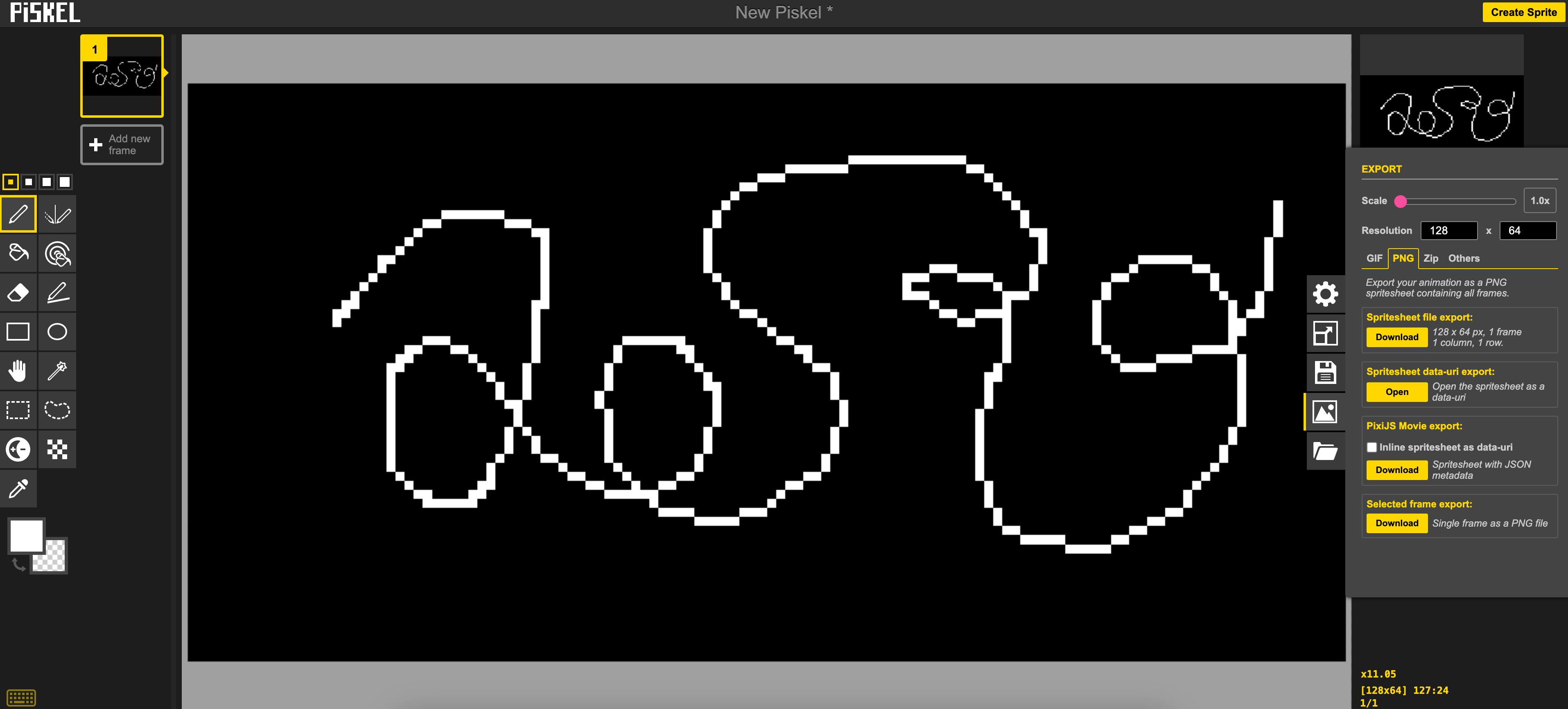
Convert your image into bitmap code
image2cpp was created by GitHub user javl and provides a handy way to create bitmaps without installing any additional software. Know more here.
Upload your image, select your preferred image settings, and generate code!
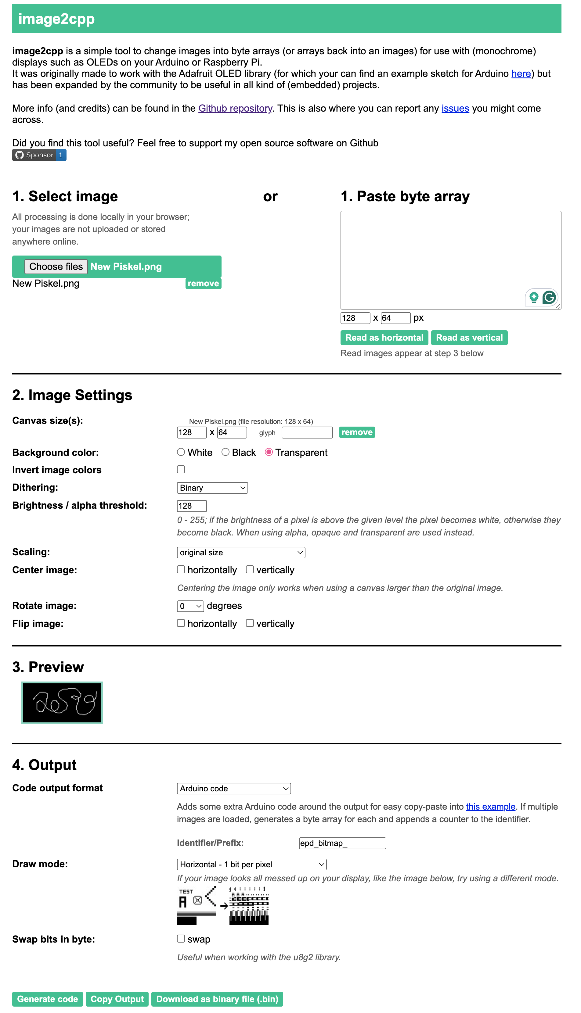
You will see the code generated at the bottom and you can paste it in Arduino directly.
Create Animation
Change the parameters at the start of the code, including the number of frames, frame sizes etc. Arduino doesn't come with a huge memory, so when you are preparing the animation, you may need to think about how many frames you want and how many frames can Arduino handle, and crop the empty space to minimize the bytes used.
The below example demonstrates two animations.
#include <SPI.h>
#include <Wire.h>
#include <Adafruit_GFX.h>
#include <Adafruit_SSD1306.h>
#define SCREEN_WIDTH 128 // OLED display width, in pixels
#define SCREEN_HEIGHT 64 // OLED display height, in pixels
#define OLED_RESET 4 // Reset pin # (or -1 if sharing Arduino reset pin)
#define SCREEN_ADDRESS 0x3D ///< See datasheet for Address; 0x3D for 128x64, 0x3C for 128x32
Adafruit_SSD1306 display(SCREEN_WIDTH, SCREEN_HEIGHT, &Wire, OLED_RESET);
// for 1st animation
int numFrame = 13;
int frameRate = 85; // 85 = 12fps, 67 = 15fps, 42 = 24fps
int counter = 0;
int bitmapWidth = 35;
int bitmapHeight = 64;
// for 2nd animation
int numFrame2 = 9;
int counter2 = 0;
int bitmapWidth2 = 78;
int bitmapHeight2 = 64;
//////////////////////////////////animation1/////////////////////////////////////////////////
// 'frame_00_delay-0', 35x64px
const unsigned char epd_bitmap_frame_00_delay_0 [] PROGMEM = {
0x00, 0x00, 0x00, 0x00, 0x00, 0x00, 0x00, 0x00, 0x00, 0x00, 0x00, 0x00, 0x00, 0x00, 0x00, 0x00,
0x00, 0x00, 0x00, 0x00, 0x00, 0x00, 0x00, 0x00, 0x00, 0x00, 0x00, 0x00, 0x00, 0x00, 0x00, 0x00,
0x00, 0x00, 0x00, 0x00, 0x00, 0x00, 0x00, 0x00, 0x00, 0x00, 0x00, 0x00, 0x00, 0x00, 0x00, 0x00,
0x00, 0x00, 0x00, 0x00, 0x00, 0x00, 0x00, 0x00, 0x00, 0x00, 0x00, 0x00, 0x00, 0x00, 0x00, 0x00,
0x00, 0x00, 0x00, 0x00, 0x00, 0x00, 0x00, 0x00, 0x00, 0x00, 0x00, 0x00, 0x00, 0x00, 0x00, 0x00,
0x00, 0x00, 0x00, 0x00, 0x00, 0x00, 0x00, 0x00, 0x00, 0x00, 0x00, 0x00, 0x00, 0x00, 0x00, 0x00,
0x00, 0x00, 0x00, 0x00, 0x00, 0x00, 0x00, 0x00, 0x00, 0x00, 0x00, 0x00, 0x00, 0x00, 0x00, 0x00,
0x00, 0x00, 0x00, 0x00, 0x00, 0x00, 0x00, 0x00, 0x00, 0x00, 0x00, 0x00, 0x00, 0x00, 0x00, 0x00,
0x00, 0x00, 0x00, 0x00, 0x00, 0x00, 0x00, 0x00, 0x00, 0x00, 0x00, 0x00, 0x00, 0x00, 0x00, 0x00,
0x00, 0x00, 0x00, 0x00, 0x00, 0x00, 0x00, 0x00, 0x00, 0x00, 0x00, 0x00, 0x00, 0x00, 0x00, 0x00,
0x00, 0x00, 0x00, 0x00, 0x00, 0x00, 0x00, 0x00, 0x00, 0x00, 0x00, 0x00, 0x00, 0x00, 0x00, 0x00,
0x00, 0x00, 0x00, 0x00, 0x00, 0x00, 0x00, 0x00, 0x00, 0x00, 0x00, 0x00, 0x00, 0x00, 0x00, 0x00,
0x00, 0x00, 0x00, 0x00, 0x00, 0x00, 0x00, 0x00, 0x00, 0x00, 0x00, 0x00, 0x00, 0x00, 0x00, 0x00,
0x00, 0x00, 0x00, 0x00, 0x00, 0x00, 0x00, 0x00, 0x00, 0x00, 0x00, 0x00, 0x00, 0x00, 0x00, 0x00,
0x00, 0x00, 0x00, 0x00, 0x00, 0x00, 0x00, 0x00, 0x00, 0x00, 0x00, 0x00, 0x00, 0x00, 0x00, 0x00,
0x00, 0x00, 0x00, 0x00, 0x00, 0x00, 0x00, 0x00, 0x00, 0x00, 0x00, 0x00, 0x00, 0x00, 0x00, 0x00,
0x00, 0x00, 0x00, 0x00, 0x00, 0x01, 0x00, 0x00, 0x00, 0x00, 0x01, 0x80, 0x00, 0x00, 0x00, 0x01,
0x80, 0x00, 0x00, 0x00, 0x01, 0x80, 0x00, 0x00, 0x00, 0x01, 0x80, 0x00, 0x00, 0x00, 0x01, 0x00,
0x00, 0x00, 0x00, 0x01, 0x00, 0x00, 0x00, 0x00, 0x00, 0x00, 0x00, 0x00, 0x00, 0x00, 0x00, 0x00,
0x00, 0x00, 0x00, 0x00, 0x00, 0x00, 0x00, 0x00, 0x00, 0x00, 0x00, 0x00, 0x00, 0x00, 0x00, 0x00
};
// 'frame_02_delay-0', 35x64px
const unsigned char epd_bitmap_frame_02_delay_0 [] PROGMEM = {
0x00, 0x00, 0x00, 0x00, 0x00, 0x00, 0x00, 0x00, 0x00, 0x00, 0x00, 0x00, 0x00, 0x00, 0x00, 0x00,
0x00, 0x00, 0x00, 0x00, 0x00, 0x00, 0x00, 0x00, 0x00, 0x00, 0x00, 0x00, 0x00, 0x00, 0x00, 0x00,
0x00, 0x00, 0x00, 0x00, 0x00, 0x00, 0x00, 0x00, 0x00, 0x00, 0x00, 0x00, 0x00, 0x00, 0x00, 0x00,
0x00, 0x00, 0x00, 0x00, 0x00, 0x00, 0x00, 0x00, 0x00, 0x00, 0x00, 0x00, 0x00, 0x00, 0x00, 0x00,
0x00, 0x00, 0x00, 0x00, 0x00, 0x00, 0x00, 0x00, 0x00, 0x00, 0x00, 0x00, 0x00, 0x00, 0x00, 0x00,
0x00, 0x00, 0x00, 0x00, 0x00, 0x00, 0x00, 0x00, 0x00, 0x00, 0x00, 0x00, 0x00, 0x00, 0x00, 0x00,
0x00, 0x00, 0x00, 0x00, 0x00, 0x00, 0x00, 0x00, 0x00, 0x00, 0x00, 0x00, 0x00, 0x00, 0x00, 0x00,
0x00, 0x00, 0x00, 0x00, 0x00, 0x00, 0x00, 0x00, 0x00, 0x00, 0x00, 0x00, 0x00, 0x00, 0x00, 0x00,
0x00, 0x00, 0x00, 0x00, 0x00, 0x00, 0x00, 0x00, 0x00, 0x00, 0x00, 0x00, 0x00, 0x00, 0x00, 0x00,
0x00, 0x00, 0x00, 0x00, 0x00, 0x00, 0x00, 0x00, 0x00, 0x00, 0x00, 0x00, 0x00, 0x00, 0x00, 0x00,
0x00, 0x00, 0x00, 0x00, 0x00, 0x00, 0x00, 0x00, 0x00, 0x00, 0x00, 0x00, 0x00, 0x00, 0x00, 0x00,
0x00, 0x00, 0x00, 0x00, 0x00, 0x00, 0x00, 0x00, 0x00, 0x00, 0x00, 0x00, 0x00, 0x00, 0x00, 0x00,
0x00, 0x00, 0x00, 0x00, 0x01, 0x00, 0x00, 0x00, 0x00, 0x03, 0x00, 0x00, 0x00, 0x00, 0x01, 0x00,
0x00, 0x00, 0x00, 0x01, 0x80, 0x00, 0x00, 0x00, 0x01, 0x80, 0x00, 0x00, 0x00, 0x01, 0x80, 0x00,
0x00, 0x00, 0x01, 0x80, 0x00, 0x00, 0x00, 0x01, 0x80, 0x00, 0x00, 0x00, 0x01, 0x80, 0x00, 0x00,
0x00, 0x01, 0x80, 0x00, 0x00, 0x00, 0x01, 0x80, 0x00, 0x00, 0x00, 0x01, 0x80, 0x00, 0x00, 0x00,
0x01, 0x80, 0x00, 0x00, 0x00, 0x01, 0x80, 0x00, 0x00, 0x00, 0x01, 0x80, 0x00, 0x00, 0x00, 0x01,
0x80, 0x00, 0x00, 0x00, 0x01, 0x80, 0x00, 0x00, 0x00, 0x01, 0x80, 0x00, 0x00, 0x00, 0x01, 0x80,
0x00, 0x00, 0x00, 0x00, 0x00, 0x00, 0x00, 0x00, 0x00, 0x00, 0x00, 0x00, 0x00, 0x00, 0x00, 0x00,
0x00, 0x00, 0x00, 0x00, 0x00, 0x00, 0x00, 0x00, 0x00, 0x00, 0x00, 0x00, 0x00, 0x00, 0x00, 0x00
};
// 'frame_01_delay-0', 35x64px
const unsigned char epd_bitmap_frame_01_delay_0 [] PROGMEM = {
0x00, 0x00, 0x00, 0x00, 0x00, 0x00, 0x00, 0x00, 0x00, 0x00, 0x00, 0x00, 0x00, 0x00, 0x00, 0x00,
0x00, 0x00, 0x00, 0x00, 0x00, 0x00, 0x00, 0x00, 0x00, 0x00, 0x00, 0x00, 0x00, 0x00, 0x00, 0x00,
0x00, 0x00, 0x00, 0x00, 0x00, 0x00, 0x00, 0x00, 0x00, 0x00, 0x00, 0x00, 0x00, 0x00, 0x00, 0x00,
0x00, 0x00, 0x00, 0x00, 0x00, 0x00, 0x00, 0x00, 0x00, 0x00, 0x00, 0x00, 0x00, 0x00, 0x00, 0x00,
0x00, 0x00, 0x00, 0x00, 0x00, 0x00, 0x00, 0x00, 0x00, 0x00, 0x00, 0x00, 0x00, 0x00, 0x00, 0x00,
0x00, 0x00, 0x00, 0x00, 0x00, 0x00, 0x00, 0x00, 0x00, 0x00, 0x00, 0x00, 0x00, 0x00, 0x00, 0x00,
0x00, 0x00, 0x00, 0x00, 0x00, 0x00, 0x00, 0x00, 0x00, 0x00, 0x00, 0x00, 0x00, 0x00, 0x00, 0x00,
0x00, 0x00, 0x00, 0x00, 0x00, 0x00, 0x00, 0x00, 0x00, 0x00, 0x00, 0x00, 0x00, 0x00, 0x00, 0x00,
0x00, 0x00, 0x00, 0x00, 0x00, 0x00, 0x00, 0x00, 0x00, 0x00, 0x00, 0x00, 0x00, 0x00, 0x00, 0x00,
0x00, 0x00, 0x00, 0x00, 0x00, 0x00, 0x00, 0x00, 0x00, 0x00, 0x00, 0x00, 0x00, 0x00, 0x00, 0x00,
0x00, 0x00, 0x00, 0x00, 0x00, 0x00, 0x00, 0x00, 0x00, 0x00, 0x00, 0x00, 0x00, 0x00, 0x00, 0x00,
0x00, 0x00, 0x00, 0x00, 0x00, 0x00, 0x00, 0x00, 0x00, 0x00, 0x00, 0x00, 0x00, 0x00, 0x00, 0x00,
0x00, 0x00, 0x00, 0x00, 0x00, 0x00, 0x00, 0x00, 0x00, 0x00, 0x00, 0x00, 0x00, 0x00, 0x00, 0x00,
0x00, 0x00, 0x00, 0x00, 0x00, 0x00, 0x00, 0x00, 0x00, 0x00, 0x00, 0x00, 0x00, 0x00, 0x00, 0x00,
0x00, 0x00, 0x00, 0x00, 0x00, 0x00, 0x00, 0x01, 0x00, 0x00, 0x00, 0x00, 0x03, 0x00, 0x00, 0x00,
0x00, 0x01, 0x00, 0x00, 0x00, 0x00, 0x01, 0x00, 0x00, 0x00, 0x00, 0x01, 0x00, 0x00, 0x00, 0x00,
0x01, 0x00, 0x00, 0x00, 0x00, 0x01, 0x00, 0x00, 0x00, 0x00, 0x01, 0x00, 0x00, 0x00, 0x00, 0x01,
0x80, 0x00, 0x00, 0x00, 0x01, 0x80, 0x00, 0x00, 0x00, 0x01, 0x80, 0x00, 0x00, 0x00, 0x01, 0x80,
0x00, 0x00, 0x00, 0x01, 0x80, 0x00, 0x00, 0x00, 0x00, 0x00, 0x00, 0x00, 0x00, 0x00, 0x00, 0x00,
0x00, 0x00, 0x00, 0x00, 0x00, 0x00, 0x00, 0x00, 0x00, 0x00, 0x00, 0x00, 0x00, 0x00, 0x00, 0x00
};
// 'frame_03_delay-0', 35x64px
const unsigned char epd_bitmap_frame_03_delay_0 [] PROGMEM = {
0x00, 0x00, 0x00, 0x00, 0x00, 0x00, 0x00, 0x00, 0x00, 0x00, 0x00, 0x00, 0x00, 0x00, 0x00, 0x00,
0x00, 0x00, 0x00, 0x00, 0x00, 0x00, 0x00, 0x00, 0x00, 0x00, 0x00, 0x00, 0x00, 0x00, 0x00, 0x00,
0x00, 0x00, 0x00, 0x00, 0x00, 0x00, 0x00, 0x00, 0x00, 0x00, 0x00, 0x00, 0x00, 0x00, 0x00, 0x00,
0x00, 0x00, 0x00, 0x00, 0x00, 0x00, 0x00, 0x00, 0x00, 0x00, 0x00, 0x00, 0x00, 0x00, 0x00, 0x00,
0x00, 0x00, 0x00, 0x00, 0x00, 0x00, 0x00, 0x00, 0x00, 0x00, 0x00, 0x00, 0x00, 0x00, 0x00, 0x00,
0x00, 0x00, 0x00, 0x00, 0x00, 0x00, 0x00, 0x00, 0x00, 0x00, 0x00, 0x00, 0x00, 0x00, 0x00, 0x00,
0x00, 0x00, 0x00, 0x00, 0x00, 0x00, 0x00, 0x00, 0x00, 0x00, 0x00, 0x00, 0x00, 0x00, 0x00, 0x00,
0x00, 0x00, 0x00, 0x00, 0x00, 0x00, 0x00, 0x00, 0x00, 0x00, 0x00, 0x00, 0x00, 0x00, 0x00, 0x00,
0x00, 0x00, 0x00, 0x01, 0x00, 0x00, 0x00, 0x00, 0x01, 0x80, 0x00, 0x00, 0x00, 0x01, 0x80, 0x00,
0x00, 0x00, 0x01, 0x80, 0x00, 0x00, 0x00, 0x01, 0x80, 0x00, 0x00, 0x00, 0x01, 0x80, 0x00, 0x00,
0x00, 0x01, 0x80, 0x00, 0x00, 0x00, 0x01, 0x80, 0x00, 0x00, 0x00, 0x01, 0x80, 0x00, 0x00, 0x00,
0x01, 0x80, 0x00, 0x00, 0x00, 0x01, 0x80, 0x00, 0x00, 0x00, 0x01, 0x80, 0x00, 0x00, 0x00, 0x01,
0x80, 0x00, 0x00, 0x00, 0x01, 0x80, 0x00, 0x00, 0x00, 0x01, 0x80, 0x00, 0x00, 0x00, 0x01, 0x80,
0x00, 0x00, 0x00, 0x01, 0x80, 0x00, 0x00, 0x00, 0x01, 0x80, 0x00, 0x00, 0x00, 0x01, 0x80, 0x00,
0x00, 0x00, 0x01, 0x80, 0x00, 0x00, 0x00, 0x01, 0x80, 0x00, 0x00, 0x00, 0x01, 0x80, 0x00, 0x00,
0x00, 0x01, 0x80, 0x00, 0x00, 0x00, 0x01, 0x80, 0x00, 0x00, 0x00, 0x01, 0x80, 0x00, 0x00, 0x00,
0x01, 0x80, 0x00, 0x00, 0x00, 0x01, 0x80, 0x00, 0x00, 0x00, 0x01, 0x80, 0x00, 0x00, 0x00, 0x01,
0x80, 0x00, 0x00, 0x00, 0x01, 0x80, 0x00, 0x00, 0x00, 0x01, 0x80, 0x00, 0x00, 0x00, 0x01, 0x80,
0x00, 0x00, 0x00, 0x01, 0x80, 0x00, 0x00, 0x00, 0x00, 0x80, 0x00, 0x00, 0x00, 0x00, 0x00, 0x00,
0x00, 0x00, 0x00, 0x00, 0x00, 0x00, 0x00, 0x00, 0x00, 0x00, 0x00, 0x00, 0x00, 0x00, 0x00, 0x00
};
// 'frame_06_delay-0', 35x64px
const unsigned char epd_bitmap_frame_06_delay_0 [] PROGMEM = {
0x00, 0x00, 0x00, 0x00, 0x00, 0x00, 0x00, 0x00, 0x00, 0x00, 0x00, 0x00, 0x00, 0x00, 0x00, 0x00,
0x00, 0x00, 0x00, 0x00, 0x00, 0x00, 0x00, 0x00, 0x00, 0x00, 0x00, 0x00, 0x00, 0x00, 0x00, 0x00,
0x00, 0x00, 0x00, 0x00, 0x00, 0x00, 0x00, 0x00, 0x00, 0x00, 0x00, 0x00, 0x00, 0x00, 0x00, 0x00,
0x00, 0x00, 0x00, 0x00, 0x00, 0x00, 0x00, 0x00, 0x00, 0x00, 0x00, 0x00, 0x00, 0x00, 0x00, 0x00,
0x00, 0x00, 0x00, 0x00, 0x00, 0x00, 0x00, 0x00, 0x00, 0x00, 0x00, 0x00, 0x00, 0x00, 0x00, 0x00,
0x00, 0x00, 0x00, 0x00, 0x00, 0x00, 0x00, 0x00, 0x00, 0x00, 0x00, 0x00, 0x00, 0x00, 0x00, 0x00,
0x00, 0x00, 0x00, 0x00, 0x03, 0x00, 0x00, 0x40, 0x00, 0x03, 0x00, 0x00, 0x60, 0x00, 0x03, 0x00,
0x00, 0xc0, 0x00, 0x01, 0x80, 0x01, 0xc0, 0x00, 0x01, 0xc0, 0x07, 0x80, 0x00, 0x00, 0xe0, 0x0f,
0x00, 0x00, 0x00, 0x78, 0x7c, 0x00, 0x00, 0x00, 0x1f, 0xf0, 0x00, 0x00, 0x00, 0x07, 0x80, 0x00,
0x00, 0x00, 0x01, 0x80, 0x00, 0x00, 0x00, 0x01, 0x80, 0x00, 0x00, 0x00, 0x01, 0x80, 0x00, 0x00,
0x00, 0x01, 0x80, 0x00, 0x00, 0x00, 0x01, 0x80, 0x00, 0x00, 0x00, 0x01, 0x80, 0x00, 0x00, 0x00,
0x01, 0x00, 0x00, 0x00, 0x00, 0x03, 0x00, 0x00, 0x00, 0x00, 0x03, 0x00, 0x00, 0x00, 0x00, 0x03,
0x00, 0x00, 0x00, 0x00, 0x03, 0x00, 0x00, 0x00, 0x00, 0x03, 0x00, 0x00, 0x00, 0x00, 0x03, 0x00,
0x00, 0x00, 0x00, 0x03, 0x00, 0x00, 0x00, 0x00, 0x03, 0x00, 0x00, 0x00, 0x00, 0x03, 0x00, 0x00,
0x00, 0x00, 0x03, 0x00, 0x00, 0x00, 0x00, 0x03, 0x00, 0x00, 0x00, 0x00, 0x03, 0x00, 0x00, 0x00,
0x00, 0x03, 0x00, 0x00, 0x00, 0x00, 0x03, 0x00, 0x00, 0x00, 0x00, 0x03, 0x00, 0x00, 0x00, 0x00,
0x03, 0x00, 0x00, 0x00, 0x00, 0x03, 0x00, 0x00, 0x00, 0x00, 0x03, 0x00, 0x00, 0x00, 0x00, 0x01,
0x00, 0x00, 0x00, 0x00, 0x01, 0x00, 0x00, 0x00, 0x00, 0x01, 0x80, 0x00, 0x00, 0x00, 0x01, 0x80,
0x00, 0x00, 0x00, 0x01, 0x80, 0x00, 0x00, 0x00, 0x01, 0x80, 0x00, 0x00, 0x00, 0x01, 0x00, 0x00,
0x00, 0x00, 0x00, 0x00, 0x00, 0x00, 0x00, 0x00, 0x00, 0x00, 0x00, 0x00, 0x00, 0x00, 0x00, 0x00
};
// 'frame_05_delay-0', 35x64px
const unsigned char epd_bitmap_frame_05_delay_0 [] PROGMEM = {
0x00, 0x00, 0x00, 0x00, 0x00, 0x00, 0x00, 0x00, 0x00, 0x00, 0x00, 0x00, 0x00, 0x00, 0x00, 0x00,
0x00, 0x00, 0x00, 0x00, 0x00, 0x00, 0x00, 0x00, 0x00, 0x00, 0x00, 0x00, 0x00, 0x00, 0x00, 0x00,
0x00, 0x00, 0x00, 0x00, 0x00, 0x00, 0x00, 0x00, 0x00, 0x00, 0x00, 0x00, 0x00, 0x00, 0x00, 0x00,
0x00, 0x00, 0x00, 0x00, 0x00, 0x00, 0x00, 0x00, 0x00, 0x00, 0x00, 0x00, 0x00, 0x00, 0x00, 0x00,
0x00, 0x00, 0x00, 0x00, 0x00, 0x00, 0x00, 0x00, 0x00, 0x00, 0x00, 0x00, 0x00, 0x00, 0x00, 0x00,
0x00, 0x00, 0x00, 0x00, 0x00, 0x00, 0x00, 0x00, 0x00, 0x00, 0x00, 0x00, 0x00, 0x00, 0x00, 0x00,
0x00, 0x00, 0x00, 0x00, 0x00, 0x00, 0x00, 0x00, 0x00, 0x00, 0x00, 0x00, 0x00, 0x00, 0x00, 0x00,
0x00, 0x00, 0x00, 0x00, 0x80, 0x00, 0x00, 0x00, 0x00, 0xc0, 0x07, 0x00, 0x00, 0x00, 0xe0, 0x0e,
0x00, 0x00, 0x00, 0x79, 0xfc, 0x00, 0x00, 0x00, 0x3f, 0xf0, 0x00, 0x00, 0x00, 0x0f, 0x80, 0x00,
0x00, 0x00, 0x03, 0x00, 0x00, 0x00, 0x00, 0x03, 0x00, 0x00, 0x00, 0x00, 0x03, 0x00, 0x00, 0x00,
0x00, 0x03, 0x00, 0x00, 0x00, 0x00, 0x03, 0x00, 0x00, 0x00, 0x00, 0x03, 0x00, 0x00, 0x00, 0x00,
0x03, 0x00, 0x00, 0x00, 0x00, 0x03, 0x00, 0x00, 0x00, 0x00, 0x03, 0x00, 0x00, 0x00, 0x00, 0x03,
0x00, 0x00, 0x00, 0x00, 0x03, 0x00, 0x00, 0x00, 0x00, 0x03, 0x00, 0x00, 0x00, 0x00, 0x03, 0x00,
0x00, 0x00, 0x00, 0x03, 0x00, 0x00, 0x00, 0x00, 0x03, 0x00, 0x00, 0x00, 0x00, 0x03, 0x00, 0x00,
0x00, 0x00, 0x03, 0x00, 0x00, 0x00, 0x00, 0x03, 0x00, 0x00, 0x00, 0x00, 0x03, 0x00, 0x00, 0x00,
0x00, 0x03, 0x00, 0x00, 0x00, 0x00, 0x03, 0x00, 0x00, 0x00, 0x00, 0x03, 0x00, 0x00, 0x00, 0x00,
0x03, 0x00, 0x00, 0x00, 0x00, 0x01, 0x00, 0x00, 0x00, 0x00, 0x01, 0x00, 0x00, 0x00, 0x00, 0x01,
0x80, 0x00, 0x00, 0x00, 0x01, 0x80, 0x00, 0x00, 0x00, 0x01, 0x80, 0x00, 0x00, 0x00, 0x01, 0x80,
0x00, 0x00, 0x00, 0x01, 0x80, 0x00, 0x00, 0x00, 0x01, 0x80, 0x00, 0x00, 0x00, 0x01, 0x00, 0x00,
0x00, 0x00, 0x00, 0x00, 0x00, 0x00, 0x00, 0x00, 0x00, 0x00, 0x00, 0x00, 0x00, 0x00, 0x00, 0x00
};
// 'frame_10_delay-0', 35x64px
const unsigned char epd_bitmap_frame_10_delay_0 [] PROGMEM = {
0x00, 0x00, 0x00, 0x00, 0x00, 0x00, 0x00, 0x00, 0x00, 0x00, 0x00, 0x00, 0x00, 0x00, 0x00, 0x00,
0x00, 0x00, 0x00, 0x00, 0x00, 0x00, 0x00, 0x00, 0x00, 0x00, 0x00, 0x00, 0x30, 0x00, 0x07, 0x00,
0x00, 0xf8, 0x00, 0x07, 0x98, 0x0c, 0xf8, 0x00, 0x07, 0xf8, 0x07, 0x98, 0x00, 0x06, 0xf0, 0x07,
0x98, 0x00, 0x06, 0x60, 0x03, 0x18, 0x00, 0x06, 0x00, 0x00, 0x08, 0x00, 0x06, 0x00, 0x00, 0x08,
0x00, 0x06, 0x00, 0x00, 0x18, 0x00, 0x06, 0x00, 0x00, 0x18, 0x00, 0x06, 0x00, 0x00, 0x18, 0x00,
0x06, 0x00, 0x00, 0x18, 0x00, 0x06, 0x00, 0x00, 0x18, 0x00, 0x06, 0x00, 0x00, 0x38, 0x00, 0x06,
0x00, 0x00, 0x30, 0x00, 0x06, 0x00, 0x00, 0x70, 0x00, 0x03, 0x00, 0x00, 0xe0, 0x00, 0x03, 0x00,
0x00, 0xc0, 0x00, 0x03, 0x80, 0x01, 0x80, 0x00, 0x01, 0xc0, 0x03, 0x80, 0x00, 0x00, 0xf0, 0x07,
0x00, 0x00, 0x00, 0x3f, 0xbe, 0x00, 0x00, 0x00, 0x0f, 0xf8, 0x00, 0x00, 0x00, 0x03, 0xe0, 0x00,
0x00, 0x00, 0x01, 0x80, 0x00, 0x00, 0x00, 0x01, 0x80, 0x00, 0x00, 0x00, 0x01, 0x80, 0x00, 0x00,
0x00, 0x01, 0x80, 0x00, 0x00, 0x00, 0x01, 0x80, 0x00, 0x00, 0x00, 0x01, 0x80, 0x00, 0x00, 0x00,
0x01, 0x80, 0x00, 0x00, 0x00, 0x01, 0x80, 0x00, 0x00, 0x00, 0x01, 0x80, 0x00, 0x00, 0x00, 0x01,
0x80, 0x00, 0x00, 0x00, 0x01, 0x00, 0x00, 0x00, 0x00, 0x01, 0x00, 0x00, 0x00, 0x00, 0x01, 0x00,
0x00, 0x00, 0x00, 0x01, 0x00, 0x00, 0x00, 0x00, 0x01, 0x00, 0x00, 0x00, 0x00, 0x01, 0x00, 0x00,
0x00, 0x00, 0x01, 0x00, 0x00, 0x00, 0x00, 0x01, 0x00, 0x00, 0x00, 0x00, 0x01, 0x00, 0x00, 0x00,
0x00, 0x01, 0x00, 0x00, 0x00, 0x00, 0x01, 0x00, 0x00, 0x00, 0x00, 0x01, 0x00, 0x00, 0x00, 0x00,
0x01, 0x00, 0x00, 0x00, 0x00, 0x01, 0x00, 0x00, 0x00, 0x00, 0x01, 0x00, 0x00, 0x00, 0x00, 0x01,
0x00, 0x00, 0x00, 0x00, 0x01, 0x00, 0x00, 0x00, 0x00, 0x01, 0x00, 0x00, 0x00, 0x00, 0x01, 0x00,
0x00, 0x00, 0x00, 0x01, 0x00, 0x00, 0x00, 0x00, 0x01, 0x00, 0x00, 0x00, 0x00, 0x01, 0x00, 0x00,
0x00, 0x00, 0x00, 0x00, 0x00, 0x00, 0x00, 0x00, 0x00, 0x00, 0x00, 0x00, 0x00, 0x00, 0x00, 0x00
};
// 'frame_08_delay-0', 35x64px
const unsigned char epd_bitmap_frame_08_delay_0 [] PROGMEM = {
0x00, 0x00, 0x00, 0x00, 0x00, 0x00, 0x00, 0x00, 0x00, 0x00, 0x00, 0x00, 0x00, 0x00, 0x00, 0x00,
0x00, 0x00, 0x00, 0x00, 0x00, 0x00, 0x00, 0x00, 0x00, 0x00, 0x00, 0x00, 0x00, 0x00, 0x06, 0x00,
0x00, 0x00, 0x00, 0x06, 0x00, 0x00, 0x00, 0x00, 0x06, 0x00, 0x00, 0x08, 0x00, 0x06, 0x00, 0x00,
0x0c, 0x00, 0x06, 0x00, 0x00, 0x08, 0x00, 0x06, 0x00, 0x00, 0x08, 0x00, 0x06, 0x00, 0x00, 0x18,
0x00, 0x06, 0x00, 0x00, 0x18, 0x00, 0x06, 0x00, 0x00, 0x18, 0x00, 0x06, 0x00, 0x00, 0x18, 0x00,
0x06, 0x00, 0x00, 0x18, 0x00, 0x06, 0x00, 0x00, 0x18, 0x00, 0x06, 0x00, 0x00, 0x30, 0x00, 0x06,
0x00, 0x00, 0x30, 0x00, 0x06, 0x00, 0x00, 0x70, 0x00, 0x03, 0x00, 0x00, 0x60, 0x00, 0x03, 0x00,
0x00, 0xe0, 0x00, 0x01, 0x80, 0x01, 0xc0, 0x00, 0x01, 0xc0, 0x07, 0x80, 0x00, 0x00, 0xe0, 0x1f,
0x00, 0x00, 0x00, 0x73, 0xfc, 0x00, 0x00, 0x00, 0x3f, 0xe0, 0x00, 0x00, 0x00, 0x0f, 0x80, 0x00,
0x00, 0x00, 0x01, 0x00, 0x00, 0x00, 0x00, 0x01, 0x00, 0x00, 0x00, 0x00, 0x01, 0x00, 0x00, 0x00,
0x00, 0x01, 0x00, 0x00, 0x00, 0x00, 0x01, 0x00, 0x00, 0x00, 0x00, 0x01, 0x00, 0x00, 0x00, 0x00,
0x01, 0x00, 0x00, 0x00, 0x00, 0x01, 0x00, 0x00, 0x00, 0x00, 0x01, 0x00, 0x00, 0x00, 0x00, 0x01,
0x00, 0x00, 0x00, 0x00, 0x01, 0x00, 0x00, 0x00, 0x00, 0x01, 0x00, 0x00, 0x00, 0x00, 0x01, 0x00,
0x00, 0x00, 0x00, 0x01, 0x00, 0x00, 0x00, 0x00, 0x01, 0x00, 0x00, 0x00, 0x00, 0x01, 0x80, 0x00,
0x00, 0x00, 0x01, 0x80, 0x00, 0x00, 0x00, 0x01, 0x80, 0x00, 0x00, 0x00, 0x01, 0x80, 0x00, 0x00,
0x00, 0x01, 0x80, 0x00, 0x00, 0x00, 0x01, 0x80, 0x00, 0x00, 0x00, 0x01, 0x80, 0x00, 0x00, 0x00,
0x01, 0x80, 0x00, 0x00, 0x00, 0x01, 0x80, 0x00, 0x00, 0x00, 0x01, 0x80, 0x00, 0x00, 0x00, 0x01,
0x80, 0x00, 0x00, 0x00, 0x01, 0x80, 0x00, 0x00, 0x00, 0x01, 0x80, 0x00, 0x00, 0x00, 0x01, 0x80,
0x00, 0x00, 0x00, 0x01, 0x80, 0x00, 0x00, 0x00, 0x01, 0x80, 0x00, 0x00, 0x00, 0x01, 0x00, 0x00,
0x00, 0x00, 0x00, 0x00, 0x00, 0x00, 0x00, 0x00, 0x00, 0x00, 0x00, 0x00, 0x00, 0x00, 0x00, 0x00
};
// 'frame_09_delay-0', 35x64px
const unsigned char epd_bitmap_frame_09_delay_0 [] PROGMEM = {
0x00, 0x00, 0x00, 0x00, 0x00, 0x00, 0x00, 0x00, 0x00, 0x00, 0x00, 0x00, 0x00, 0x00, 0x00, 0x00,
0x00, 0x00, 0x00, 0x00, 0x00, 0x00, 0x00, 0x00, 0x00, 0x06, 0x00, 0x00, 0x30, 0x00, 0x07, 0x00,
0x00, 0x78, 0x00, 0x07, 0x80, 0x00, 0x78, 0x00, 0x07, 0x80, 0x00, 0x18, 0x00, 0x06, 0x00, 0x00,
0x18, 0x00, 0x06, 0x00, 0x00, 0x18, 0x00, 0x06, 0x00, 0x00, 0x18, 0x00, 0x06, 0x00, 0x00, 0x18,
0x00, 0x06, 0x00, 0x00, 0x18, 0x00, 0x06, 0x00, 0x00, 0x18, 0x00, 0x06, 0x00, 0x00, 0x10, 0x00,
0x06, 0x00, 0x00, 0x10, 0x00, 0x06, 0x00, 0x00, 0x30, 0x00, 0x06, 0x00, 0x00, 0x30, 0x00, 0x02,
0x00, 0x00, 0x30, 0x00, 0x03, 0x00, 0x00, 0x70, 0x00, 0x03, 0x00, 0x00, 0x60, 0x00, 0x03, 0x00,
0x01, 0xc0, 0x00, 0x03, 0x80, 0x03, 0x80, 0x00, 0x01, 0x80, 0x07, 0x00, 0x00, 0x00, 0xc0, 0x1e,
0x00, 0x00, 0x00, 0xff, 0xf8, 0x00, 0x00, 0x00, 0x3f, 0xf0, 0x00, 0x00, 0x00, 0x03, 0x80, 0x00,
0x00, 0x00, 0x01, 0x80, 0x00, 0x00, 0x00, 0x01, 0x80, 0x00, 0x00, 0x00, 0x01, 0x80, 0x00, 0x00,
0x00, 0x01, 0x80, 0x00, 0x00, 0x00, 0x01, 0x80, 0x00, 0x00, 0x00, 0x01, 0x80, 0x00, 0x00, 0x00,
0x01, 0x80, 0x00, 0x00, 0x00, 0x01, 0x80, 0x00, 0x00, 0x00, 0x01, 0x80, 0x00, 0x00, 0x00, 0x01,
0x80, 0x00, 0x00, 0x00, 0x01, 0x80, 0x00, 0x00, 0x00, 0x01, 0x00, 0x00, 0x00, 0x00, 0x01, 0x00,
0x00, 0x00, 0x00, 0x03, 0x00, 0x00, 0x00, 0x00, 0x03, 0x00, 0x00, 0x00, 0x00, 0x03, 0x00, 0x00,
0x00, 0x00, 0x03, 0x00, 0x00, 0x00, 0x00, 0x03, 0x00, 0x00, 0x00, 0x00, 0x03, 0x00, 0x00, 0x00,
0x00, 0x01, 0x00, 0x00, 0x00, 0x00, 0x01, 0x00, 0x00, 0x00, 0x00, 0x01, 0x80, 0x00, 0x00, 0x00,
0x01, 0x80, 0x00, 0x00, 0x00, 0x01, 0x80, 0x00, 0x00, 0x00, 0x01, 0x80, 0x00, 0x00, 0x00, 0x01,
0x80, 0x00, 0x00, 0x00, 0x01, 0x80, 0x00, 0x00, 0x00, 0x01, 0x80, 0x00, 0x00, 0x00, 0x01, 0x80,
0x00, 0x00, 0x00, 0x01, 0x80, 0x00, 0x00, 0x00, 0x01, 0x80, 0x00, 0x00, 0x00, 0x01, 0x80, 0x00,
0x00, 0x00, 0x00, 0x00, 0x00, 0x00, 0x00, 0x00, 0x00, 0x00, 0x00, 0x00, 0x00, 0x00, 0x00, 0x00
};
// 'frame_04_delay-0', 35x64px
const unsigned char epd_bitmap_frame_04_delay_0 [] PROGMEM = {
0x00, 0x00, 0x00, 0x00, 0x00, 0x00, 0x00, 0x00, 0x00, 0x00, 0x00, 0x00, 0x00, 0x00, 0x00, 0x00,
0x00, 0x00, 0x00, 0x00, 0x00, 0x00, 0x00, 0x00, 0x00, 0x00, 0x00, 0x00, 0x00, 0x00, 0x00, 0x00,
0x00, 0x00, 0x00, 0x00, 0x00, 0x00, 0x00, 0x00, 0x00, 0x00, 0x00, 0x00, 0x00, 0x00, 0x00, 0x00,
0x00, 0x00, 0x00, 0x00, 0x00, 0x00, 0x00, 0x00, 0x00, 0x00, 0x00, 0x00, 0x00, 0x00, 0x00, 0x00,
0x00, 0x00, 0x00, 0x00, 0x00, 0x00, 0x00, 0x00, 0x00, 0x00, 0x00, 0x00, 0x00, 0x00, 0x00, 0x00,
0x00, 0x00, 0x00, 0x00, 0x00, 0x00, 0x00, 0x00, 0x00, 0x00, 0x00, 0x00, 0x00, 0x00, 0x00, 0x00,
0x00, 0x00, 0x00, 0x00, 0x00, 0x00, 0x00, 0x00, 0x00, 0x00, 0x00, 0x00, 0x00, 0x00, 0x00, 0x00,
0x00, 0x00, 0x00, 0x00, 0x00, 0x00, 0x00, 0x00, 0x00, 0x00, 0x00, 0x00, 0x00, 0x00, 0x00, 0x08,
0x00, 0x00, 0x00, 0x3c, 0x3c, 0x00, 0x00, 0x00, 0x3f, 0xf8, 0x00, 0x00, 0x00, 0x07, 0xe0, 0x00,
0x00, 0x00, 0x01, 0x00, 0x00, 0x00, 0x00, 0x01, 0x00, 0x00, 0x00, 0x00, 0x01, 0x00, 0x00, 0x00,
0x00, 0x01, 0x00, 0x00, 0x00, 0x00, 0x01, 0x80, 0x00, 0x00, 0x00, 0x01, 0x80, 0x00, 0x00, 0x00,
0x01, 0x80, 0x00, 0x00, 0x00, 0x01, 0x80, 0x00, 0x00, 0x00, 0x01, 0x80, 0x00, 0x00, 0x00, 0x01,
0x80, 0x00, 0x00, 0x00, 0x01, 0x80, 0x00, 0x00, 0x00, 0x01, 0x80, 0x00, 0x00, 0x00, 0x01, 0x80,
0x00, 0x00, 0x00, 0x01, 0x80, 0x00, 0x00, 0x00, 0x01, 0x80, 0x00, 0x00, 0x00, 0x01, 0x80, 0x00,
0x00, 0x00, 0x01, 0x80, 0x00, 0x00, 0x00, 0x01, 0x80, 0x00, 0x00, 0x00, 0x01, 0x80, 0x00, 0x00,
0x00, 0x01, 0x80, 0x00, 0x00, 0x00, 0x01, 0x80, 0x00, 0x00, 0x00, 0x01, 0x80, 0x00, 0x00, 0x00,
0x01, 0x80, 0x00, 0x00, 0x00, 0x01, 0x80, 0x00, 0x00, 0x00, 0x01, 0x80, 0x00, 0x00, 0x00, 0x01,
0x80, 0x00, 0x00, 0x00, 0x01, 0x80, 0x00, 0x00, 0x00, 0x01, 0x80, 0x00, 0x00, 0x00, 0x01, 0x80,
0x00, 0x00, 0x00, 0x01, 0x80, 0x00, 0x00, 0x00, 0x01, 0x80, 0x00, 0x00, 0x00, 0x01, 0x00, 0x00,
0x00, 0x00, 0x00, 0x00, 0x00, 0x00, 0x00, 0x00, 0x00, 0x00, 0x00, 0x00, 0x00, 0x00, 0x00, 0x00
};
// 'frame_07_delay-0', 35x64px
const unsigned char epd_bitmap_frame_07_delay_0 [] PROGMEM = {
0x00, 0x00, 0x00, 0x00, 0x00, 0x00, 0x00, 0x00, 0x00, 0x00, 0x00, 0x00, 0x00, 0x00, 0x00, 0x00,
0x00, 0x00, 0x00, 0x00, 0x00, 0x00, 0x00, 0x00, 0x00, 0x00, 0x00, 0x00, 0x00, 0x00, 0x00, 0x00,
0x00, 0x00, 0x00, 0x00, 0x00, 0x00, 0x00, 0x00, 0x00, 0x00, 0x00, 0x00, 0x00, 0x00, 0x00, 0x00,
0x00, 0x00, 0x00, 0x00, 0x00, 0x00, 0x00, 0x00, 0x00, 0x00, 0x00, 0x00, 0x00, 0x00, 0x00, 0x00,
0x00, 0x06, 0x00, 0x00, 0x00, 0x00, 0x06, 0x00, 0x00, 0x18, 0x00, 0x06, 0x00, 0x00, 0x18, 0x00,
0x06, 0x00, 0x00, 0x18, 0x00, 0x06, 0x00, 0x00, 0x18, 0x00, 0x06, 0x00, 0x00, 0x30, 0x00, 0x06,
0x00, 0x00, 0x30, 0x00, 0x03, 0x00, 0x00, 0x70, 0x00, 0x03, 0x00, 0x00, 0x60, 0x00, 0x03, 0x00,
0x00, 0xe0, 0x00, 0x03, 0x80, 0x01, 0xc0, 0x00, 0x01, 0x80, 0x03, 0x80, 0x00, 0x00, 0xc0, 0x0f,
0x00, 0x00, 0x00, 0xfb, 0xfc, 0x00, 0x00, 0x00, 0x3f, 0xf0, 0x00, 0x00, 0x00, 0x07, 0x80, 0x00,
0x00, 0x00, 0x03, 0x00, 0x00, 0x00, 0x00, 0x03, 0x00, 0x00, 0x00, 0x00, 0x01, 0x00, 0x00, 0x00,
0x00, 0x03, 0x00, 0x00, 0x00, 0x00, 0x03, 0x00, 0x00, 0x00, 0x00, 0x03, 0x00, 0x00, 0x00, 0x00,
0x03, 0x00, 0x00, 0x00, 0x00, 0x03, 0x00, 0x00, 0x00, 0x00, 0x03, 0x00, 0x00, 0x00, 0x00, 0x03,
0x00, 0x00, 0x00, 0x00, 0x03, 0x00, 0x00, 0x00, 0x00, 0x03, 0x00, 0x00, 0x00, 0x00, 0x03, 0x00,
0x00, 0x00, 0x00, 0x03, 0x00, 0x00, 0x00, 0x00, 0x03, 0x00, 0x00, 0x00, 0x00, 0x03, 0x00, 0x00,
0x00, 0x00, 0x01, 0x00, 0x00, 0x00, 0x00, 0x01, 0x00, 0x00, 0x00, 0x00, 0x01, 0x00, 0x00, 0x00,
0x00, 0x01, 0x00, 0x00, 0x00, 0x00, 0x01, 0x00, 0x00, 0x00, 0x00, 0x01, 0x00, 0x00, 0x00, 0x00,
0x01, 0x00, 0x00, 0x00, 0x00, 0x01, 0x00, 0x00, 0x00, 0x00, 0x01, 0x00, 0x00, 0x00, 0x00, 0x01,
0x00, 0x00, 0x00, 0x00, 0x01, 0x00, 0x00, 0x00, 0x00, 0x01, 0x00, 0x00, 0x00, 0x00, 0x01, 0x00,
0x00, 0x00, 0x00, 0x01, 0x80, 0x00, 0x00, 0x00, 0x01, 0x00, 0x00, 0x00, 0x00, 0x01, 0x00, 0x00,
0x00, 0x00, 0x00, 0x00, 0x00, 0x00, 0x00, 0x00, 0x00, 0x00, 0x00, 0x00, 0x00, 0x00, 0x00, 0x00
};
// 'frame_12_delay-0', 35x64px
const unsigned char epd_bitmap_frame_12_delay_0 [] PROGMEM = {
0x00, 0x00, 0x00, 0x00, 0x00, 0x00, 0x00, 0x00, 0x00, 0x00, 0x00, 0x01, 0x80, 0x00, 0x00, 0x00,
0x03, 0xc0, 0x00, 0x00, 0x00, 0x07, 0xe0, 0x00, 0x00, 0x06, 0x0e, 0x70, 0x70, 0x00, 0x07, 0x1c,
0x38, 0x70, 0x00, 0x07, 0x98, 0x1c, 0xf8, 0x00, 0x07, 0xf8, 0x0f, 0xd8, 0x00, 0x06, 0xf0, 0x07,
0x98, 0x00, 0x06, 0x70, 0x03, 0x0c, 0x00, 0x06, 0x00, 0x00, 0x08, 0x00, 0x06, 0x00, 0x00, 0x18,
0x00, 0x06, 0x00, 0x00, 0x18, 0x00, 0x06, 0x00, 0x00, 0x18, 0x00, 0x06, 0x00, 0x00, 0x18, 0x00,
0x06, 0x00, 0x00, 0x18, 0x00, 0x06, 0x00, 0x00, 0x30, 0x00, 0x06, 0x00, 0x00, 0x30, 0x00, 0x06,
0x00, 0x00, 0x70, 0x00, 0x03, 0x00, 0x00, 0x60, 0x00, 0x03, 0x00, 0x00, 0xe0, 0x00, 0x03, 0x00,
0x00, 0xc0, 0x00, 0x03, 0x80, 0x01, 0x80, 0x00, 0x01, 0xc0, 0x03, 0x80, 0x00, 0x00, 0xe0, 0x07,
0x00, 0x00, 0x00, 0x79, 0x3e, 0x00, 0x00, 0x00, 0x3f, 0xf8, 0x00, 0x00, 0x00, 0x07, 0xc0, 0x00,
0x00, 0x00, 0x01, 0x80, 0x00, 0x00, 0x00, 0x01, 0x80, 0x00, 0x00, 0x00, 0x01, 0x80, 0x00, 0x00,
0x00, 0x01, 0x80, 0x00, 0x00, 0x00, 0x01, 0x80, 0x00, 0x00, 0x00, 0x01, 0x80, 0x00, 0x00, 0x00,
0x01, 0x80, 0x00, 0x00, 0x00, 0x01, 0x80, 0x00, 0x00, 0x00, 0x01, 0x80, 0x00, 0x00, 0x00, 0x01,
0x80, 0x00, 0x00, 0x00, 0x01, 0x80, 0x00, 0x00, 0x00, 0x01, 0x80, 0x00, 0x00, 0x00, 0x01, 0x80,
0x00, 0x00, 0x00, 0x01, 0x80, 0x00, 0x00, 0x00, 0x01, 0x00, 0x00, 0x00, 0x00, 0x01, 0x00, 0x00,
0x00, 0x00, 0x01, 0x00, 0x00, 0x00, 0x00, 0x01, 0x00, 0x00, 0x00, 0x00, 0x01, 0x00, 0x00, 0x00,
0x00, 0x01, 0x00, 0x00, 0x00, 0x00, 0x01, 0x00, 0x00, 0x00, 0x00, 0x01, 0x00, 0x00, 0x00, 0x00,
0x03, 0x00, 0x00, 0x00, 0x00, 0x03, 0x00, 0x00, 0x00, 0x00, 0x03, 0x00, 0x00, 0x00, 0x00, 0x03,
0x00, 0x00, 0x00, 0x00, 0x03, 0x00, 0x00, 0x00, 0x00, 0x03, 0x00, 0x00, 0x00, 0x00, 0x01, 0x00,
0x00, 0x00, 0x00, 0x01, 0x00, 0x00, 0x00, 0x00, 0x01, 0x00, 0x00, 0x00, 0x00, 0x01, 0x00, 0x00,
0x00, 0x00, 0x01, 0x00, 0x00, 0x00, 0x00, 0x01, 0x00, 0x00, 0x00, 0x00, 0x00, 0x00, 0x00, 0x00
};
// 'frame_11_delay-0', 35x64px
const unsigned char epd_bitmap_frame_11_delay_0 [] PROGMEM = {
0x00, 0x00, 0x00, 0x00, 0x00, 0x00, 0x00, 0x00, 0x00, 0x00, 0x00, 0x00, 0x00, 0x00, 0x00, 0x00,
0x00, 0x00, 0x00, 0x00, 0x00, 0x00, 0x00, 0x00, 0x00, 0x00, 0x0e, 0x30, 0x30, 0x00, 0x07, 0x1c,
0x38, 0x78, 0x00, 0x07, 0x18, 0x1c, 0xf8, 0x00, 0x07, 0xf8, 0x0f, 0xd8, 0x00, 0x07, 0xf0, 0x07,
0x98, 0x00, 0x06, 0x60, 0x03, 0x18, 0x00, 0x06, 0x00, 0x00, 0x18, 0x00, 0x06, 0x00, 0x00, 0x18,
0x00, 0x06, 0x00, 0x00, 0x18, 0x00, 0x06, 0x00, 0x00, 0x18, 0x00, 0x06, 0x00, 0x00, 0x18, 0x00,
0x06, 0x00, 0x00, 0x30, 0x00, 0x06, 0x00, 0x00, 0x30, 0x00, 0x06, 0x00, 0x00, 0x30, 0x00, 0x03,
0x00, 0x00, 0x60, 0x00, 0x03, 0x00, 0x00, 0x60, 0x00, 0x03, 0x00, 0x00, 0xe0, 0x00, 0x03, 0x80,
0x00, 0xc0, 0x00, 0x01, 0x80, 0x01, 0x80, 0x00, 0x01, 0xc0, 0x07, 0x80, 0x00, 0x00, 0xe0, 0x1e,
0x00, 0x00, 0x00, 0x7b, 0xf8, 0x00, 0x00, 0x00, 0x3f, 0xe0, 0x00, 0x00, 0x00, 0x07, 0x00, 0x00,
0x00, 0x00, 0x03, 0x00, 0x00, 0x00, 0x00, 0x03, 0x00, 0x00, 0x00, 0x00, 0x03, 0x00, 0x00, 0x00,
0x00, 0x03, 0x00, 0x00, 0x00, 0x00, 0x03, 0x00, 0x00, 0x00, 0x00, 0x03, 0x00, 0x00, 0x00, 0x00,
0x03, 0x00, 0x00, 0x00, 0x00, 0x03, 0x00, 0x00, 0x00, 0x00, 0x03, 0x00, 0x00, 0x00, 0x00, 0x03,
0x00, 0x00, 0x00, 0x00, 0x03, 0x00, 0x00, 0x00, 0x00, 0x03, 0x00, 0x00, 0x00, 0x00, 0x03, 0x00,
0x00, 0x00, 0x00, 0x01, 0x00, 0x00, 0x00, 0x00, 0x01, 0x00, 0x00, 0x00, 0x00, 0x01, 0x00, 0x00,
0x00, 0x00, 0x01, 0x80, 0x00, 0x00, 0x00, 0x01, 0x80, 0x00, 0x00, 0x00, 0x01, 0x80, 0x00, 0x00,
0x00, 0x01, 0x80, 0x00, 0x00, 0x00, 0x01, 0x80, 0x00, 0x00, 0x00, 0x01, 0x80, 0x00, 0x00, 0x00,
0x01, 0x80, 0x00, 0x00, 0x00, 0x01, 0x80, 0x00, 0x00, 0x00, 0x01, 0x80, 0x00, 0x00, 0x00, 0x01,
0x80, 0x00, 0x00, 0x00, 0x01, 0x80, 0x00, 0x00, 0x00, 0x01, 0x80, 0x00, 0x00, 0x00, 0x01, 0x80,
0x00, 0x00, 0x00, 0x01, 0x80, 0x00, 0x00, 0x00, 0x01, 0x80, 0x00, 0x00, 0x00, 0x01, 0x80, 0x00,
0x00, 0x00, 0x01, 0x80, 0x00, 0x00, 0x00, 0x00, 0x00, 0x00, 0x00, 0x00, 0x00, 0x00, 0x00, 0x00
};
// Array of all bitmaps for convenience. (Total bytes used to store images in PROGMEM = 4368)
const int epd_bitmap_allArray_LEN = 13;
const unsigned char* epd_bitmap_allArray[13] = {
epd_bitmap_frame_00_delay_0,
epd_bitmap_frame_01_delay_0,
epd_bitmap_frame_02_delay_0,
epd_bitmap_frame_03_delay_0,
epd_bitmap_frame_04_delay_0,
epd_bitmap_frame_05_delay_0,
epd_bitmap_frame_06_delay_0,
epd_bitmap_frame_07_delay_0,
epd_bitmap_frame_08_delay_0,
epd_bitmap_frame_09_delay_0,
epd_bitmap_frame_10_delay_0,
epd_bitmap_frame_11_delay_0,
epd_bitmap_frame_12_delay_0
};
//////////////////////////////////animation1/////////////////////////////////////////////////
// '3', 78x64px
const unsigned char epd_bitmap_3 [] PROGMEM = {
0x00, 0x00, 0x00, 0x00, 0x00, 0x00, 0x00, 0x00, 0x00, 0x00, 0x00, 0x00, 0x00, 0x00, 0x00, 0x00,
0x00, 0x00, 0x00, 0x00, 0x00, 0x00, 0x00, 0x00, 0x00, 0x00, 0x00, 0x00, 0x00, 0x00, 0x00, 0x00,
0x01, 0xc0, 0x00, 0x00, 0x00, 0x00, 0x00, 0x00, 0x00, 0x00, 0x03, 0xf0, 0x3f, 0xff, 0x80, 0x00,
0x00, 0x00, 0x00, 0x00, 0x03, 0xf1, 0xff, 0xff, 0xf0, 0x00, 0x00, 0x00, 0x00, 0x00, 0x03, 0xcf,
0xff, 0xff, 0xfe, 0x00, 0x00, 0x00, 0x00, 0x00, 0x07, 0x9f, 0xff, 0xff, 0xff, 0x80, 0x00, 0x00,
0x00, 0x00, 0x06, 0x7f, 0xff, 0xff, 0xff, 0xe0, 0x00, 0x00, 0x00, 0x00, 0x04, 0xff, 0xff, 0xff,
0xff, 0xf0, 0x00, 0x00, 0x00, 0x00, 0x01, 0xff, 0xff, 0xff, 0xff, 0xfc, 0x00, 0x00, 0x00, 0x00,
0x03, 0xff, 0xff, 0xff, 0xff, 0xfe, 0x00, 0x00, 0x00, 0x00, 0x07, 0xff, 0xff, 0xff, 0xff, 0xff,
0x00, 0x00, 0x00, 0x00, 0x0f, 0xff, 0xff, 0xff, 0xff, 0xff, 0x80, 0x00, 0x00, 0x00, 0x0f, 0xff,
0xff, 0xff, 0xff, 0xff, 0xdf, 0xc0, 0x00, 0x00, 0x1f, 0xff, 0xff, 0xff, 0xff, 0xff, 0xff, 0xe0,
0x00, 0x00, 0x1f, 0xff, 0xff, 0xff, 0xff, 0xff, 0xff, 0xc0, 0x00, 0x00, 0x3f, 0xff, 0xff, 0xff,
0xff, 0xff, 0xff, 0xc0, 0x00, 0x00, 0x3f, 0xff, 0xff, 0xff, 0xff, 0xff, 0xff, 0xc0, 0x00, 0x0e,
0x3f, 0xff, 0xff, 0xff, 0xff, 0xff, 0xff, 0xc0, 0x01, 0xdf, 0x3f, 0xff, 0xff, 0xff, 0xff, 0xff,
0xff, 0x80, 0x03, 0xff, 0x7f, 0xff, 0xff, 0xff, 0xff, 0xff, 0xff, 0x80, 0x01, 0xff, 0x7f, 0xc7,
0xff, 0xff, 0xff, 0xff, 0xff, 0x80, 0x00, 0xfe, 0x7f, 0x83, 0xff, 0xfb, 0xff, 0xff, 0xff, 0x00,
0x01, 0xff, 0x7f, 0xc7, 0xff, 0xf0, 0xff, 0xff, 0xff, 0x00, 0x01, 0xff, 0x7f, 0xff, 0x87, 0xf0,
0xff, 0xff, 0xfe, 0x00, 0x01, 0xff, 0x7f, 0xff, 0xd3, 0xf9, 0xff, 0xff, 0xfc, 0x00, 0x01, 0xef,
0x7f, 0xff, 0xd7, 0xff, 0xff, 0xff, 0xfc, 0x00, 0x00, 0x10, 0xff, 0xff, 0xd7, 0xff, 0xff, 0xff,
0xfc, 0x00, 0x00, 0x11, 0xff, 0xff, 0xd7, 0xff, 0xff, 0xff, 0xfc, 0x00, 0x00, 0xd1, 0xff, 0xff,
0xdf, 0xff, 0xff, 0xff, 0xfc, 0x00, 0x00, 0xf1, 0xff, 0xff, 0xef, 0xff, 0xff, 0xff, 0xfc, 0x00,
0x00, 0xf1, 0xff, 0xff, 0xff, 0xff, 0xff, 0xff, 0xfc, 0x00, 0x00, 0x71, 0xff, 0xff, 0xff, 0xff,
0xff, 0xff, 0xfc, 0x00, 0x00, 0x71, 0xff, 0xff, 0xff, 0xff, 0xff, 0xff, 0xf8, 0x00, 0x00, 0x10,
0xff, 0xff, 0xff, 0xff, 0xff, 0xff, 0xf8, 0x00, 0x00, 0x1f, 0xff, 0xff, 0xff, 0xff, 0xff, 0xff,
0xf8, 0x00, 0x00, 0x1f, 0x7f, 0xff, 0xff, 0xff, 0xff, 0xff, 0xf0, 0x00, 0x00, 0x1e, 0x3f, 0xff,
0xff, 0xff, 0xff, 0xff, 0xf0, 0x00, 0x00, 0x18, 0x0f, 0xff, 0xff, 0xff, 0xff, 0xff, 0xf0, 0x00,
0x00, 0x10, 0x03, 0xff, 0xff, 0xff, 0xff, 0xff, 0xe0, 0x00, 0x00, 0x10, 0x00, 0x3f, 0xff, 0xff,
0xff, 0xff, 0xc0, 0x00, 0x00, 0x1f, 0xef, 0xff, 0xff, 0xff, 0xff, 0xff, 0x80, 0x00, 0x00, 0x27,
0xff, 0xff, 0xff, 0xff, 0xff, 0xff, 0x00, 0x00, 0x00, 0x3f, 0xff, 0xff, 0xff, 0xff, 0xff, 0xfc,
0x00, 0x00, 0x00, 0x07, 0xff, 0xff, 0xff, 0xff, 0xf8, 0x00, 0x00, 0x00, 0x00, 0x1f, 0xff, 0xff,
0xff, 0xff, 0xfc, 0x00, 0x00, 0x00, 0x00, 0x30, 0xff, 0xff, 0xff, 0xff, 0xfe, 0x00, 0x00, 0x00,
0x00, 0x30, 0x00, 0x7f, 0xff, 0xff, 0xff, 0x00, 0x00, 0x00, 0x00, 0x30, 0x00, 0x7f, 0xff, 0xff,
0xff, 0x00, 0x00, 0x00, 0x00, 0x30, 0x00, 0x7f, 0xff, 0xff, 0xff, 0x00, 0x00, 0x00, 0x00, 0x30,
0x00, 0xff, 0xff, 0xfe, 0xff, 0x8f, 0x00, 0x00, 0x00, 0x00, 0x00, 0xff, 0xff, 0xfe, 0xfb, 0x9f,
0x80, 0x00, 0x00, 0x00, 0x00, 0xff, 0xff, 0xfe, 0xfb, 0xbf, 0x80, 0x00, 0x00, 0x00, 0x00, 0xff,
0xff, 0xfe, 0xfb, 0x9f, 0x00, 0x00, 0x00, 0x00, 0x00, 0xff, 0xff, 0xfe, 0xfb, 0xd8, 0x00, 0x00,
0x00, 0x00, 0x01, 0xff, 0xff, 0xfe, 0xfb, 0xd0, 0x00, 0x00, 0x00, 0x00, 0x01, 0xff, 0xff, 0xfe,
0xf7, 0xd0, 0x00, 0x00, 0x00, 0x00, 0x01, 0xff, 0xff, 0xfe, 0xf7, 0xc0, 0x00, 0x00, 0x00, 0x00,
0x01, 0xff, 0xff, 0xff, 0x77, 0xc0, 0x00, 0x00, 0x00, 0x00, 0x01, 0xff, 0xff, 0xff, 0x67, 0xc0,
0x00, 0x00, 0x00, 0x00, 0x01, 0xff, 0xff, 0xff, 0x8f, 0xc0, 0x00, 0x00, 0x00, 0x00, 0x01, 0xff,
0xff, 0xff, 0xff, 0xc0, 0x00, 0x00, 0x00, 0x00, 0x01, 0xff, 0xff, 0xff, 0xff, 0xc0, 0x00, 0x00
};
// '1', 78x64px
const unsigned char epd_bitmap_1 [] PROGMEM = {
0x00, 0x00, 0x00, 0x00, 0x00, 0x00, 0x00, 0x00, 0x00, 0x00, 0x00, 0x00, 0x00, 0x00, 0x00, 0x00,
0x00, 0x00, 0x00, 0x00, 0x3f, 0xff, 0xff, 0xff, 0xf0, 0x07, 0xff, 0xff, 0xff, 0xfc, 0x3f, 0xff,
0xff, 0xff, 0x00, 0x00, 0x3f, 0xff, 0xff, 0xfc, 0x3f, 0xff, 0xff, 0xf8, 0x3f, 0xff, 0x03, 0xff,
0xff, 0xfc, 0x3f, 0xff, 0xfe, 0x01, 0xff, 0xff, 0xf0, 0xff, 0xff, 0xfc, 0x3f, 0xff, 0xf0, 0x0f,
0xff, 0xff, 0xfe, 0x3f, 0xff, 0xfc, 0x3f, 0xff, 0xc7, 0x9f, 0xff, 0xff, 0xff, 0x8f, 0xff, 0xfc,
0x3f, 0xff, 0x1e, 0x7f, 0xff, 0xff, 0xff, 0xe7, 0xff, 0xfc, 0x3f, 0xfe, 0x7c, 0xff, 0xff, 0xff,
0xff, 0xf3, 0xff, 0xfc, 0x3f, 0xfe, 0xf9, 0xff, 0xff, 0xff, 0xff, 0xf8, 0xff, 0xfc, 0x3f, 0xfe,
0xf3, 0xff, 0xff, 0xff, 0xff, 0xfe, 0x7f, 0xfc, 0x3f, 0xfe, 0x77, 0xff, 0xff, 0xff, 0xff, 0xff,
0x3f, 0xfc, 0x3f, 0xff, 0x27, 0xff, 0xff, 0xff, 0xff, 0xff, 0xbf, 0xfc, 0x3f, 0xff, 0x8f, 0xff,
0xff, 0xff, 0xff, 0xff, 0x9f, 0xfc, 0x3f, 0xff, 0xdf, 0xff, 0xff, 0xff, 0xff, 0xff, 0xcf, 0xfc,
0x3f, 0xff, 0x9f, 0xff, 0xff, 0xff, 0xff, 0xff, 0xe3, 0xfc, 0x3f, 0xff, 0x9f, 0xff, 0xff, 0xff,
0xff, 0xff, 0xf8, 0xfc, 0x3f, 0x9f, 0xbf, 0xff, 0xff, 0xff, 0xff, 0xff, 0xfe, 0x7c, 0x3e, 0x07,
0x3f, 0xff, 0xff, 0xff, 0xff, 0xff, 0xff, 0x3c, 0x20, 0xf3, 0x3f, 0xff, 0xff, 0xff, 0xff, 0xff,
0xff, 0x9c, 0x0e, 0xf3, 0x7f, 0xef, 0xff, 0xff, 0xff, 0xff, 0xff, 0xcc, 0x0f, 0xf3, 0x7f, 0xc7,
0xff, 0xff, 0xff, 0xff, 0xff, 0xe4, 0x0f, 0xf3, 0x7f, 0x83, 0xff, 0xf1, 0xff, 0xff, 0xff, 0xe4,
0x27, 0xf2, 0x7f, 0xc7, 0xff, 0xf0, 0xff, 0xff, 0xff, 0xf0, 0x37, 0xf8, 0xff, 0xef, 0x87, 0xf0,
0xff, 0xff, 0xff, 0xf0, 0x27, 0xf8, 0xff, 0xff, 0xd3, 0xf0, 0xff, 0xff, 0xff, 0xf0, 0x27, 0xf9,
0xff, 0xff, 0xd7, 0xff, 0xff, 0xff, 0xff, 0xc4, 0x27, 0x01, 0xff, 0xff, 0xd7, 0xff, 0xff, 0xff,
0xfc, 0x0c, 0x30, 0x79, 0xff, 0xff, 0xd7, 0xff, 0xff, 0xff, 0xfc, 0xfc, 0x3f, 0xf9, 0xff, 0xff,
0xcf, 0xff, 0xff, 0xff, 0xfd, 0xfc, 0x3f, 0xf9, 0xff, 0xff, 0xef, 0xff, 0xff, 0xff, 0xfd, 0xfc,
0x3f, 0xf9, 0xff, 0xff, 0xff, 0xff, 0xff, 0xff, 0xfd, 0xfc, 0x3f, 0xfd, 0xff, 0xff, 0xff, 0xff,
0xff, 0xff, 0xf9, 0xfc, 0x3f, 0xfd, 0xff, 0xff, 0xff, 0xff, 0xff, 0xff, 0xf9, 0xfc, 0x3f, 0xfc,
0xff, 0xff, 0xff, 0xff, 0xff, 0xff, 0xf9, 0xfc, 0x3f, 0xfe, 0xff, 0xff, 0xff, 0xff, 0xff, 0xff,
0xfb, 0xfc, 0x3f, 0xfe, 0x7f, 0xff, 0xff, 0xff, 0xff, 0xff, 0xf3, 0xfc, 0x3f, 0xff, 0x3f, 0xff,
0xff, 0xff, 0xff, 0xff, 0xf3, 0xfc, 0x3f, 0xff, 0x8f, 0xff, 0xff, 0xff, 0xff, 0xff, 0xe7, 0xfc,
0x3f, 0xff, 0xc1, 0xff, 0xff, 0xff, 0xff, 0xff, 0xe7, 0xfc, 0x3f, 0xd0, 0x00, 0x3f, 0xff, 0xff,
0xff, 0xff, 0xcf, 0xfc, 0x3f, 0x9f, 0x83, 0xff, 0xff, 0xff, 0xff, 0xff, 0x9f, 0xfc, 0x3f, 0x27,
0xff, 0xff, 0xff, 0xff, 0xff, 0xff, 0x3f, 0xfc, 0x3f, 0x2f, 0xff, 0xff, 0xff, 0xff, 0xff, 0xf8,
0x7f, 0xfc, 0x3f, 0x87, 0xff, 0xff, 0xff, 0xff, 0xf8, 0x01, 0xff, 0xfc, 0x3f, 0xd7, 0xff, 0xff,
0xff, 0xff, 0xfc, 0x0f, 0xff, 0xfc, 0x3f, 0xf0, 0xff, 0xff, 0xff, 0xff, 0xfe, 0x7f, 0xff, 0xfc,
0x3f, 0xfc, 0x00, 0x7f, 0xff, 0xff, 0xff, 0x7f, 0xff, 0xfc, 0x3f, 0xff, 0xe0, 0x7f, 0xff, 0xff,
0xff, 0x3f, 0xff, 0xfc, 0x3f, 0xff, 0xfe, 0x7f, 0xff, 0xff, 0xff, 0x3f, 0xff, 0xfc, 0x3f, 0xff,
0xfe, 0xff, 0xff, 0xfe, 0xff, 0xbe, 0x7f, 0xfc, 0x3f, 0xff, 0xfe, 0xff, 0xff, 0xfe, 0xf3, 0x9c,
0x3f, 0xfc, 0x3f, 0xff, 0xfc, 0xff, 0xff, 0xfe, 0xf3, 0x91, 0x9f, 0xfc, 0x3f, 0xff, 0xfc, 0xff,
0xff, 0xfe, 0xf3, 0x87, 0x9f, 0xfc, 0x3f, 0xff, 0xfc, 0xff, 0xff, 0xfe, 0xf3, 0x9f, 0xbf, 0xfc,
0x3f, 0xff, 0xfd, 0xff, 0xff, 0xfe, 0xf3, 0xdf, 0x3f, 0xfc, 0x3f, 0xff, 0xfd, 0xff, 0xff, 0xfe,
0xf3, 0xdc, 0x7f, 0xfc, 0x3f, 0xff, 0xfd, 0xff, 0xff, 0xfe, 0x77, 0xd9, 0xff, 0xfc, 0x3f, 0xff,
0xfd, 0xff, 0xff, 0xff, 0x77, 0xd3, 0xff, 0xfc, 0x3f, 0xff, 0xfd, 0xff, 0xff, 0xff, 0x67, 0xc7,
0xff, 0xfc, 0x3f, 0xff, 0xf9, 0xff, 0xff, 0xff, 0x8f, 0xc7, 0xff, 0xfc, 0x3f, 0xff, 0xf9, 0xff,
0xff, 0xff, 0xff, 0xcf, 0xff, 0xfc, 0x3f, 0xff, 0xfd, 0xff, 0xff, 0xff, 0xff, 0xcf, 0xff, 0xfc
};
// '4', 78x64px
const unsigned char epd_bitmap_4 [] PROGMEM = {
0x00, 0x00, 0x00, 0x00, 0x00, 0x00, 0x00, 0x00, 0x00, 0x00, 0x00, 0x00, 0x00, 0x00, 0x00, 0x00,
0x00, 0x00, 0x00, 0x00, 0x00, 0x00, 0x00, 0x00, 0x00, 0x00, 0x00, 0x00, 0x00, 0x00, 0x00, 0x00,
0x00, 0x00, 0x00, 0x00, 0x00, 0x00, 0x00, 0x00, 0x00, 0x00, 0x07, 0xc0, 0x3f, 0xff, 0x80, 0x00,
0x00, 0x00, 0x00, 0x00, 0x0f, 0xf1, 0xff, 0xff, 0xf0, 0x00, 0x00, 0x00, 0x00, 0x00, 0x0f, 0xcf,
0xff, 0xff, 0xfe, 0x00, 0x00, 0x00, 0x00, 0x00, 0x0f, 0x9f, 0xff, 0xff, 0xff, 0x80, 0x00, 0x00,
0x00, 0x00, 0x0e, 0x7f, 0xff, 0xff, 0xff, 0xe0, 0x00, 0x00, 0x00, 0x00, 0x0c, 0xff, 0xff, 0xff,
0xff, 0xf0, 0x00, 0x00, 0x00, 0x00, 0x0d, 0xff, 0xff, 0xff, 0xff, 0xfc, 0x00, 0x00, 0x00, 0x00,
0x0b, 0xff, 0xff, 0xff, 0xff, 0xfe, 0x00, 0x00, 0x00, 0x00, 0x07, 0xff, 0xff, 0xff, 0xff, 0xff,
0x00, 0x00, 0x00, 0x00, 0x0f, 0xff, 0xff, 0xff, 0xff, 0xff, 0x80, 0x00, 0x00, 0x00, 0x0f, 0xff,
0xff, 0xff, 0xff, 0xff, 0x80, 0x00, 0x00, 0x00, 0x1f, 0xff, 0xff, 0xff, 0xff, 0xff, 0xff, 0x00,
0x00, 0x00, 0x1f, 0xff, 0xff, 0xff, 0xff, 0xff, 0xff, 0xe0, 0x00, 0x00, 0x3f, 0xff, 0xff, 0xff,
0xff, 0xff, 0xff, 0xf0, 0x00, 0x00, 0x3f, 0xff, 0xff, 0xff, 0xff, 0xff, 0xff, 0xf0, 0x00, 0x63,
0x3f, 0xff, 0xff, 0xff, 0xff, 0xff, 0xff, 0xe0, 0x00, 0xff, 0xbf, 0xff, 0xff, 0xff, 0xff, 0xff,
0xff, 0xe0, 0x00, 0xff, 0xbf, 0xff, 0xff, 0xff, 0xff, 0xff, 0xff, 0xe0, 0x00, 0xff, 0xbf, 0xff,
0xff, 0xff, 0xff, 0xff, 0xff, 0xc0, 0x00, 0x7f, 0x7f, 0xff, 0xff, 0xff, 0xff, 0xff, 0xff, 0xc0,
0x00, 0xff, 0x7f, 0xc7, 0xff, 0xff, 0xff, 0xff, 0xff, 0x80, 0x00, 0xff, 0xbf, 0xff, 0x87, 0xf7,
0xff, 0xff, 0xff, 0x00, 0x00, 0xff, 0xbf, 0xff, 0xd3, 0xf0, 0xff, 0xff, 0xfe, 0x00, 0x00, 0x77,
0xbf, 0xff, 0xd7, 0xff, 0xff, 0xff, 0xfc, 0x00, 0x00, 0x08, 0x7f, 0xff, 0xd7, 0xff, 0xff, 0xff,
0xfc, 0x00, 0x00, 0x09, 0xff, 0xff, 0xd7, 0xff, 0xff, 0xff, 0xfc, 0x00, 0x00, 0x09, 0xff, 0xff,
0xdf, 0xff, 0xff, 0xff, 0xfc, 0x00, 0x00, 0x79, 0xff, 0xff, 0xef, 0xff, 0xff, 0xff, 0xfc, 0x00,
0x00, 0x79, 0xff, 0xff, 0xff, 0xff, 0xff, 0xff, 0xfc, 0x00, 0x00, 0x79, 0xff, 0xff, 0xff, 0xff,
0xff, 0xff, 0xfc, 0x00, 0x00, 0x39, 0xff, 0xff, 0xff, 0xff, 0xff, 0xff, 0xf8, 0x00, 0x00, 0x08,
0xff, 0xff, 0xff, 0xff, 0xff, 0xff, 0xf8, 0x00, 0x00, 0x0f, 0xff, 0xff, 0xff, 0xff, 0xff, 0xff,
0xf8, 0x00, 0x00, 0x0f, 0x7f, 0xff, 0xff, 0xff, 0xff, 0xff, 0xf0, 0x00, 0x00, 0x1e, 0x3f, 0xff,
0xff, 0xff, 0xff, 0xff, 0xf0, 0x00, 0x00, 0x1c, 0x0f, 0xff, 0xff, 0xff, 0xff, 0xff, 0xf0, 0x00,
0x00, 0x18, 0x03, 0xff, 0xff, 0xff, 0xff, 0xff, 0xe0, 0x00, 0x00, 0x10, 0x00, 0x3f, 0xff, 0xff,
0xff, 0xff, 0xc0, 0x00, 0x00, 0x1f, 0xef, 0xff, 0xff, 0xff, 0xff, 0xff, 0x80, 0x00, 0x00, 0x27,
0xff, 0xff, 0xff, 0xff, 0xff, 0xff, 0x00, 0x00, 0x00, 0x3f, 0xff, 0xff, 0xff, 0xff, 0xff, 0xfc,
0x00, 0x00, 0x00, 0x07, 0xff, 0xff, 0xff, 0xff, 0xf8, 0x00, 0x00, 0x00, 0x00, 0x1f, 0xff, 0xff,
0xff, 0xff, 0xfc, 0x00, 0x00, 0x00, 0x00, 0x10, 0xff, 0xff, 0xff, 0xff, 0xfe, 0x00, 0x00, 0x00,
0x00, 0x10, 0x00, 0x7f, 0xff, 0xff, 0xff, 0x00, 0x00, 0x00, 0x00, 0x30, 0x00, 0x7f, 0xff, 0xff,
0xff, 0x38, 0x00, 0x00, 0x00, 0x30, 0x00, 0x7f, 0xff, 0xff, 0xff, 0x38, 0x00, 0x00, 0x00, 0x30,
0x00, 0xff, 0xff, 0xfe, 0xff, 0xb8, 0x00, 0x00, 0x00, 0x20, 0x00, 0xff, 0xff, 0xfe, 0xfb, 0xb8,
0x00, 0x00, 0x00, 0x00, 0x00, 0xff, 0xff, 0xfe, 0xfb, 0xb0, 0x00, 0x00, 0x00, 0x00, 0x00, 0xff,
0xff, 0xfe, 0xfb, 0x90, 0x00, 0x00, 0x00, 0x00, 0x00, 0xff, 0xff, 0xfe, 0xfb, 0xd0, 0x00, 0x00,
0x00, 0x00, 0x01, 0xff, 0xff, 0xfe, 0xfb, 0xd0, 0x00, 0x00, 0x00, 0x00, 0x01, 0xff, 0xff, 0xfe,
0xf7, 0xd0, 0x00, 0x00, 0x00, 0x00, 0x01, 0xff, 0xff, 0xfe, 0xf7, 0xc0, 0x00, 0x00, 0x00, 0x00,
0x01, 0xff, 0xff, 0xff, 0x77, 0xc0, 0x00, 0x00, 0x00, 0x00, 0x01, 0xff, 0xff, 0xff, 0x67, 0xc0,
0x00, 0x00, 0x00, 0x00, 0x01, 0xff, 0xff, 0xff, 0x8f, 0xc0, 0x00, 0x00, 0x00, 0x00, 0x01, 0xff,
0xff, 0xff, 0xff, 0xc0, 0x00, 0x00, 0x00, 0x00, 0x01, 0xff, 0xff, 0xff, 0xff, 0xc0, 0x00, 0x00
};
// '5', 78x64px
const unsigned char epd_bitmap_5 [] PROGMEM = {
0x00, 0x00, 0x00, 0x00, 0x00, 0x00, 0x00, 0x00, 0x00, 0x00, 0x00, 0x00, 0x00, 0x00, 0x00, 0x00,
0x00, 0x00, 0x00, 0x00, 0x00, 0x00, 0x00, 0x00, 0x00, 0x00, 0x00, 0x00, 0x00, 0x00, 0x00, 0x00,
0x00, 0x00, 0x00, 0x00, 0x00, 0x00, 0x00, 0x00, 0x00, 0x00, 0x00, 0x00, 0x3f, 0xff, 0x80, 0x00,
0x00, 0x00, 0x00, 0x00, 0x1f, 0xe1, 0xff, 0xff, 0xf0, 0x00, 0x00, 0x00, 0x00, 0x00, 0x1f, 0xcf,
0xff, 0xff, 0xfe, 0x00, 0x00, 0x00, 0x00, 0x00, 0x1f, 0x9f, 0xff, 0xff, 0xff, 0x80, 0x00, 0x00,
0x00, 0x00, 0x1e, 0x7f, 0xff, 0xff, 0xff, 0xe0, 0x00, 0x00, 0x00, 0x00, 0x1c, 0xff, 0xff, 0xff,
0xff, 0xf0, 0x00, 0x00, 0x00, 0x00, 0x19, 0xff, 0xff, 0xff, 0xff, 0xfc, 0x00, 0x00, 0x00, 0x00,
0x1b, 0xff, 0xff, 0xff, 0xff, 0xfe, 0x00, 0x00, 0x00, 0x00, 0x07, 0xff, 0xff, 0xff, 0xff, 0xff,
0x00, 0x00, 0x00, 0x00, 0x0f, 0xff, 0xff, 0xff, 0xff, 0xff, 0x80, 0x00, 0x00, 0x00, 0x0f, 0xff,
0xff, 0xff, 0xff, 0xff, 0x80, 0x00, 0x00, 0x00, 0x1f, 0xff, 0xff, 0xff, 0xff, 0xff, 0xf0, 0x00,
0x00, 0x00, 0x1f, 0xff, 0xff, 0xff, 0xff, 0xff, 0xfe, 0x00, 0x00, 0x00, 0x3f, 0xff, 0xff, 0xff,
0xff, 0xff, 0xff, 0x80, 0x00, 0x00, 0x3f, 0xff, 0xff, 0xff, 0xff, 0xff, 0xff, 0xc0, 0x00, 0x00,
0xbf, 0xff, 0xff, 0xff, 0xff, 0xff, 0xff, 0xf0, 0x00, 0x7f, 0xdf, 0xff, 0xff, 0xff, 0xff, 0xff,
0xff, 0xf0, 0x00, 0x7f, 0xdf, 0xef, 0xff, 0xff, 0xff, 0xff, 0xff, 0xf0, 0x00, 0x7f, 0xdf, 0xc7,
0xff, 0xff, 0xff, 0xff, 0xff, 0xf0, 0x00, 0x3f, 0xbf, 0x83, 0xff, 0xf1, 0xff, 0xff, 0xff, 0xe0,
0x00, 0x3f, 0xbf, 0xc7, 0xff, 0xf0, 0xff, 0xff, 0xff, 0xc0, 0x00, 0x7f, 0xdf, 0xef, 0x87, 0xf0,
0xff, 0xff, 0xff, 0x80, 0x00, 0x7f, 0xdf, 0xff, 0xd3, 0xf0, 0xff, 0xff, 0xff, 0x00, 0x00, 0x3b,
0xdf, 0xff, 0xd7, 0xff, 0xff, 0xff, 0xfc, 0x00, 0x00, 0x04, 0x3f, 0xff, 0xd7, 0xff, 0xff, 0xff,
0xfc, 0x00, 0x00, 0x05, 0xff, 0xff, 0xd7, 0xff, 0xff, 0xff, 0xfc, 0x00, 0x00, 0x3d, 0xff, 0xff,
0xdf, 0xff, 0xff, 0xff, 0xfc, 0x00, 0x00, 0x3d, 0xff, 0xff, 0xef, 0xff, 0xff, 0xff, 0xfc, 0x00,
0x00, 0x3d, 0xff, 0xff, 0xff, 0xff, 0xff, 0xff, 0xfc, 0x00, 0x00, 0x3d, 0xff, 0xff, 0xff, 0xff,
0xff, 0xff, 0xfc, 0x00, 0x00, 0x1d, 0xff, 0xff, 0xff, 0xff, 0xff, 0xff, 0xf8, 0x00, 0x00, 0x0c,
0xff, 0xff, 0xff, 0xff, 0xff, 0xff, 0xf8, 0x00, 0x00, 0x0f, 0xff, 0xff, 0xff, 0xff, 0xff, 0xff,
0xf8, 0x00, 0x00, 0x0f, 0xff, 0xff, 0xff, 0xff, 0xff, 0xff, 0xf0, 0x00, 0x00, 0x0f, 0xbf, 0xff,
0xff, 0xff, 0xff, 0xff, 0xf0, 0x00, 0x00, 0x0f, 0x0f, 0xff, 0xff, 0xff, 0xff, 0xff, 0xf0, 0x00,
0x00, 0x08, 0x03, 0xff, 0xff, 0xff, 0xff, 0xff, 0xe0, 0x00, 0x00, 0x08, 0x00, 0x3f, 0xff, 0xff,
0xff, 0xff, 0xc0, 0x00, 0x00, 0x1f, 0xef, 0xff, 0xff, 0xff, 0xff, 0xff, 0x80, 0x00, 0x00, 0x27,
0xff, 0xff, 0xff, 0xff, 0xff, 0xff, 0x00, 0x00, 0x00, 0x3f, 0xff, 0xff, 0xff, 0xff, 0xff, 0xfc,
0x00, 0x00, 0x00, 0x07, 0xff, 0xff, 0xff, 0xff, 0xf8, 0x00, 0x00, 0x00, 0x00, 0x1f, 0xff, 0xff,
0xff, 0xff, 0xfc, 0x00, 0x00, 0x00, 0x00, 0x10, 0xff, 0xff, 0xff, 0xff, 0xfe, 0x00, 0x00, 0x00,
0x00, 0x30, 0x00, 0x7f, 0xff, 0xff, 0xff, 0x20, 0x00, 0x00, 0x00, 0x30, 0x00, 0x7f, 0xff, 0xff,
0xff, 0x70, 0x00, 0x00, 0x00, 0x30, 0x00, 0x7f, 0xff, 0xff, 0xff, 0x30, 0x00, 0x00, 0x00, 0x30,
0x00, 0xff, 0xff, 0xfe, 0xff, 0xb0, 0x00, 0x00, 0x00, 0x20, 0x00, 0xff, 0xff, 0xfe, 0xfb, 0xb0,
0x00, 0x00, 0x00, 0x00, 0x00, 0xff, 0xff, 0xfe, 0xfb, 0xb0, 0x00, 0x00, 0x00, 0x00, 0x00, 0xff,
0xff, 0xfe, 0xfb, 0x90, 0x00, 0x00, 0x00, 0x00, 0x00, 0xff, 0xff, 0xfe, 0xfb, 0xd0, 0x00, 0x00,
0x00, 0x00, 0x01, 0xff, 0xff, 0xfe, 0xfb, 0xd0, 0x00, 0x00, 0x00, 0x00, 0x01, 0xff, 0xff, 0xfe,
0xf7, 0xd0, 0x00, 0x00, 0x00, 0x00, 0x01, 0xff, 0xff, 0xfe, 0xf7, 0xd0, 0x00, 0x00, 0x00, 0x00,
0x01, 0xff, 0xff, 0xff, 0x77, 0xd0, 0x00, 0x00, 0x00, 0x00, 0x01, 0xff, 0xff, 0xff, 0x67, 0xc0,
0x00, 0x00, 0x00, 0x00, 0x01, 0xff, 0xff, 0xff, 0x8f, 0xc0, 0x00, 0x00, 0x00, 0x00, 0x01, 0xff,
0xff, 0xff, 0xff, 0xc0, 0x00, 0x00, 0x00, 0x00, 0x01, 0xff, 0xff, 0xff, 0xff, 0xc0, 0x00, 0x00
};
// '6', 78x64px
const unsigned char epd_bitmap_6 [] PROGMEM = {
0x00, 0x00, 0x00, 0x00, 0x00, 0x00, 0x00, 0x00, 0x00, 0x00, 0x00, 0x00, 0x00, 0x00, 0x00, 0x00,
0x00, 0x00, 0x00, 0x00, 0x01, 0xff, 0xff, 0xff, 0xf0, 0x07, 0xff, 0xff, 0xff, 0xfc, 0x01, 0xff,
0xff, 0xff, 0x00, 0x00, 0x3f, 0xff, 0xff, 0xfc, 0x01, 0xff, 0xff, 0xf8, 0x3f, 0xff, 0x83, 0xff,
0xff, 0xfc, 0x01, 0xff, 0xfe, 0x01, 0xff, 0xff, 0xf0, 0xff, 0xff, 0xfc, 0x01, 0xff, 0xf0, 0x0f,
0xff, 0xff, 0xfe, 0x3f, 0xff, 0xfc, 0x01, 0xff, 0xc7, 0x9f, 0xff, 0xff, 0xff, 0x8f, 0xff, 0xfc,
0x01, 0xff, 0x1f, 0x7f, 0xff, 0xff, 0xff, 0xe7, 0xff, 0xfc, 0x01, 0xfe, 0x7c, 0xff, 0xff, 0xff,
0xff, 0xf3, 0xff, 0xfc, 0x01, 0xfe, 0xf9, 0xff, 0xff, 0xff, 0xff, 0xfc, 0xff, 0xfc, 0x01, 0xfe,
0xfb, 0xff, 0xff, 0xff, 0xff, 0xfe, 0x7f, 0xfc, 0x01, 0xfe, 0x77, 0xff, 0xff, 0xff, 0xff, 0xff,
0x3f, 0xfc, 0x01, 0xff, 0x2f, 0xff, 0xff, 0xff, 0xff, 0xff, 0xbf, 0xfc, 0x01, 0xff, 0x8f, 0xff,
0xff, 0xff, 0xff, 0xff, 0x9f, 0xfc, 0x01, 0xff, 0xdf, 0xff, 0xff, 0xff, 0xff, 0xff, 0xcf, 0xfc,
0x01, 0xff, 0x9f, 0xff, 0xff, 0xff, 0xff, 0xff, 0xe3, 0xfc, 0x01, 0xff, 0xbf, 0xff, 0xff, 0xff,
0xff, 0xff, 0xf8, 0xfc, 0x01, 0x98, 0x3f, 0xff, 0xff, 0xff, 0xff, 0xff, 0xfe, 0x7c, 0x00, 0x63,
0x3f, 0xff, 0xff, 0xff, 0xff, 0xff, 0xff, 0x3c, 0x00, 0xff, 0xbf, 0xff, 0xff, 0xff, 0xff, 0xff,
0xff, 0x9c, 0x00, 0xff, 0xbf, 0xef, 0xff, 0xff, 0xff, 0xff, 0xff, 0xcc, 0x00, 0xff, 0xbf, 0xc7,
0xff, 0xff, 0xff, 0xff, 0xff, 0xe4, 0x00, 0x7f, 0x7f, 0x83, 0xff, 0xf1, 0xff, 0xff, 0xff, 0xf4,
0x00, 0xff, 0x7f, 0xc7, 0xff, 0xf0, 0xff, 0xff, 0xff, 0xf0, 0x00, 0xff, 0xbf, 0xef, 0x87, 0xf0,
0xff, 0xff, 0xff, 0xf0, 0x00, 0xff, 0xbf, 0xff, 0xd3, 0xf0, 0xff, 0xff, 0xff, 0xf0, 0x00, 0x77,
0xbf, 0xff, 0xd7, 0xff, 0xff, 0xff, 0xff, 0xc4, 0x01, 0x08, 0x7f, 0xff, 0xd7, 0xff, 0xff, 0xff,
0xfe, 0x0c, 0x01, 0xf9, 0xff, 0xff, 0xd7, 0xff, 0xff, 0xff, 0xfc, 0xfc, 0x01, 0xf9, 0xff, 0xff,
0xdf, 0xff, 0xff, 0xff, 0xfd, 0xfc, 0x01, 0xf9, 0xff, 0xff, 0xef, 0xff, 0xff, 0xff, 0xfd, 0xfc,
0x01, 0xf9, 0xff, 0xff, 0xff, 0xff, 0xff, 0xff, 0xfd, 0xfc, 0x01, 0xfd, 0xff, 0xff, 0xff, 0xff,
0xff, 0xff, 0xfd, 0xfc, 0x01, 0xfd, 0xff, 0xff, 0xff, 0xff, 0xff, 0xff, 0xf9, 0xfc, 0x01, 0xfc,
0xff, 0xff, 0xff, 0xff, 0xff, 0xff, 0xf9, 0xfc, 0x01, 0xff, 0xff, 0xff, 0xff, 0xff, 0xff, 0xff,
0xfb, 0xfc, 0x01, 0xff, 0x7f, 0xff, 0xff, 0xff, 0xff, 0xff, 0xf3, 0xfc, 0x01, 0xff, 0x3f, 0xff,
0xff, 0xff, 0xff, 0xff, 0xf3, 0xfc, 0x01, 0xff, 0x8f, 0xff, 0xff, 0xff, 0xff, 0xff, 0xf7, 0xfc,
0x01, 0xff, 0xc3, 0xff, 0xff, 0xff, 0xff, 0xff, 0xe7, 0xfc, 0x01, 0xd0, 0x00, 0x3f, 0xff, 0xff,
0xff, 0xff, 0xcf, 0xfc, 0x01, 0x9f, 0xef, 0xff, 0xff, 0xff, 0xff, 0xff, 0x9f, 0xfc, 0x01, 0x27,
0xff, 0xff, 0xff, 0xff, 0xff, 0xff, 0x3f, 0xfc, 0x01, 0x3f, 0xff, 0xff, 0xff, 0xff, 0xff, 0xfc,
0x7f, 0xfc, 0x01, 0x87, 0xff, 0xff, 0xff, 0xff, 0xf8, 0x01, 0xff, 0xfc, 0x01, 0xdf, 0xff, 0xff,
0xff, 0xff, 0xfc, 0x0f, 0xff, 0xfc, 0x01, 0xf0, 0xff, 0xff, 0xff, 0xff, 0xfe, 0x1f, 0xff, 0xfc,
0x01, 0xfc, 0x00, 0x7f, 0xff, 0xff, 0xff, 0x0f, 0xff, 0xfc, 0x01, 0xff, 0xe0, 0x7f, 0xff, 0xff,
0xff, 0x67, 0xff, 0xfc, 0x01, 0xff, 0xfe, 0x7f, 0xff, 0xff, 0xff, 0x33, 0xff, 0xfc, 0x01, 0xff,
0xfe, 0xff, 0xff, 0xfe, 0xff, 0xbb, 0xff, 0xfc, 0x01, 0xff, 0xfe, 0xff, 0xff, 0xfe, 0xfb, 0xbb,
0xff, 0xfc, 0x01, 0xff, 0xfc, 0xff, 0xff, 0xfe, 0xfb, 0xb9, 0xff, 0xfc, 0x01, 0xff, 0xfc, 0xff,
0xff, 0xfe, 0xfb, 0x99, 0xff, 0xfc, 0x01, 0xff, 0xfc, 0xff, 0xff, 0xfe, 0xfb, 0xdd, 0xff, 0xfc,
0x01, 0xff, 0xfd, 0xff, 0xff, 0xfe, 0xfb, 0xdd, 0xff, 0xfc, 0x01, 0xff, 0xfd, 0xff, 0xff, 0xfe,
0xf7, 0xdd, 0xff, 0xfc, 0x01, 0xff, 0xfd, 0xff, 0xff, 0xfe, 0xf7, 0xd9, 0xff, 0xfc, 0x01, 0xff,
0xfd, 0xff, 0xff, 0xff, 0x77, 0xd9, 0xff, 0xfc, 0x01, 0xff, 0xfd, 0xff, 0xff, 0xff, 0x67, 0xdb,
0xff, 0xfc, 0x01, 0xff, 0xf9, 0xff, 0xff, 0xff, 0x8f, 0xd3, 0xff, 0xfc, 0x01, 0xff, 0xf9, 0xff,
0xff, 0xff, 0xff, 0xc7, 0xff, 0xfc, 0x01, 0xff, 0xfd, 0xff, 0xff, 0xff, 0xff, 0xc7, 0xff, 0xfc
};
// '8', 78x64px
const unsigned char epd_bitmap_8 [] PROGMEM = {
0x00, 0x00, 0x00, 0x00, 0x00, 0x00, 0x00, 0x00, 0x00, 0x00, 0x1f, 0xff, 0xfe, 0xff, 0xff, 0xff,
0xff, 0xff, 0xff, 0xf0, 0x1f, 0xff, 0xfc, 0x1f, 0xf0, 0x07, 0xff, 0xff, 0xff, 0xf0, 0x1f, 0xff,
0xf9, 0xc7, 0x00, 0x00, 0x3f, 0xff, 0xff, 0xf0, 0x1f, 0xff, 0xfb, 0xf0, 0x3f, 0xff, 0x83, 0xff,
0xff, 0xf0, 0x1f, 0xff, 0xf3, 0xf1, 0xff, 0xff, 0xf0, 0xff, 0xff, 0xf0, 0x1f, 0xff, 0xf3, 0xcf,
0xff, 0xff, 0xfe, 0x3f, 0xff, 0xf0, 0x1f, 0xff, 0xf7, 0x9f, 0xff, 0xff, 0xff, 0x8f, 0xff, 0xf0,
0x1f, 0xff, 0xf6, 0x7f, 0xff, 0xff, 0xff, 0xe7, 0xff, 0xf0, 0x1f, 0xff, 0xe4, 0xff, 0xff, 0xff,
0xff, 0xf3, 0xff, 0xf0, 0x1f, 0xff, 0xe1, 0xff, 0xff, 0xff, 0xff, 0xfc, 0xff, 0xf0, 0x1f, 0xff,
0xe3, 0xff, 0xff, 0xff, 0xff, 0xfe, 0x7f, 0xf0, 0x1f, 0xff, 0xe7, 0xff, 0xff, 0xff, 0xff, 0xff,
0x3f, 0xf0, 0x1f, 0xff, 0xef, 0xff, 0xff, 0xff, 0xff, 0xff, 0x80, 0x10, 0x1f, 0xff, 0xcf, 0xff,
0xff, 0xff, 0xff, 0xff, 0xdf, 0xc0, 0x1f, 0xff, 0xdf, 0xff, 0xff, 0xff, 0xff, 0xff, 0xff, 0xe0,
0x1f, 0xff, 0x9f, 0xff, 0xff, 0xff, 0xff, 0xff, 0xff, 0xc0, 0x1f, 0xff, 0xbf, 0xff, 0xff, 0xff,
0xff, 0xff, 0xff, 0xc0, 0x1f, 0xe7, 0xbf, 0xff, 0xff, 0xff, 0xff, 0xff, 0xff, 0xd0, 0x1c, 0x13,
0x3f, 0xff, 0xff, 0xff, 0xff, 0xff, 0xff, 0xd0, 0x13, 0x3d, 0x3f, 0xff, 0xff, 0xff, 0xff, 0xff,
0xff, 0x90, 0x17, 0xfd, 0x7f, 0xef, 0xff, 0xff, 0xff, 0xff, 0xff, 0x90, 0x17, 0xfd, 0x7f, 0xc7,
0xff, 0xff, 0xff, 0xff, 0xff, 0xb0, 0x17, 0xf9, 0x7f, 0x83, 0xff, 0xf1, 0xff, 0xff, 0xff, 0x30,
0x1b, 0xfc, 0x7f, 0xc7, 0xff, 0xf0, 0xff, 0xff, 0xff, 0x70, 0x13, 0xfe, 0xff, 0xef, 0x87, 0xf0,
0xff, 0xff, 0xfe, 0x70, 0x17, 0xfe, 0xff, 0xff, 0xd3, 0xf0, 0xff, 0xff, 0xfc, 0xf0, 0x17, 0xfe,
0xff, 0xff, 0xd7, 0xff, 0xff, 0xff, 0xfc, 0xf0, 0x1b, 0x81, 0xff, 0xff, 0xd7, 0xff, 0xff, 0xff,
0xfc, 0xf0, 0x1c, 0x79, 0xff, 0xff, 0xd7, 0xff, 0xff, 0xff, 0xfc, 0xf0, 0x1f, 0xf9, 0xff, 0xff,
0xdf, 0xff, 0xff, 0xff, 0xfd, 0xf0, 0x1f, 0xf9, 0xff, 0xff, 0xef, 0xff, 0xff, 0xff, 0xfd, 0xf0,
0x1f, 0xf9, 0xff, 0xff, 0xff, 0xff, 0xff, 0xff, 0xfd, 0xf0, 0x1f, 0xfd, 0xff, 0xff, 0xff, 0xff,
0xff, 0xff, 0xfd, 0xf0, 0x1f, 0xfd, 0xff, 0xff, 0xff, 0xff, 0xff, 0xff, 0xf9, 0xf0, 0x1f, 0xfe,
0xff, 0xff, 0xff, 0xff, 0xff, 0xff, 0xf9, 0xf0, 0x1f, 0xfe, 0xff, 0xff, 0xff, 0xff, 0xff, 0xff,
0xfb, 0xf0, 0x1f, 0xfe, 0x7f, 0xff, 0xff, 0xff, 0xff, 0xff, 0xf3, 0xf0, 0x1f, 0xff, 0x3f, 0xff,
0xff, 0xff, 0xff, 0xff, 0xf3, 0xf0, 0x1f, 0xff, 0x8f, 0xff, 0xff, 0xff, 0xff, 0xff, 0xf7, 0xf0,
0x1f, 0xff, 0xc3, 0xff, 0xff, 0xff, 0xff, 0xff, 0xe7, 0xf0, 0x1f, 0xd0, 0x00, 0x3f, 0xff, 0xff,
0xff, 0xff, 0xcf, 0xf0, 0x1f, 0x9f, 0xef, 0xff, 0xff, 0xff, 0xff, 0xff, 0x9f, 0xf0, 0x1f, 0x27,
0xff, 0xff, 0xff, 0xff, 0xff, 0xff, 0x3f, 0xf0, 0x1f, 0x3f, 0xff, 0xff, 0xff, 0xff, 0xff, 0xfc,
0x7f, 0xf0, 0x1f, 0x87, 0xff, 0xff, 0xff, 0xff, 0xf8, 0x01, 0xff, 0xf0, 0x1f, 0xdf, 0xff, 0xff,
0xff, 0xff, 0xfc, 0x0f, 0xff, 0xf0, 0x1f, 0xf0, 0xff, 0xff, 0xff, 0xff, 0xfe, 0x7f, 0xff, 0xf0,
0x1f, 0xfc, 0x00, 0x7f, 0xff, 0xff, 0xff, 0x7f, 0xff, 0xf0, 0x1f, 0xff, 0xe0, 0x7f, 0xff, 0xff,
0xff, 0x3f, 0xff, 0xf0, 0x1f, 0xff, 0xfe, 0x7f, 0xff, 0xff, 0xff, 0x3c, 0xff, 0xf0, 0x1f, 0xff,
0xfe, 0xff, 0xff, 0xfe, 0xff, 0xb8, 0x7f, 0xf0, 0x1f, 0xff, 0xfe, 0xff, 0xff, 0xfe, 0xfb, 0x93,
0x7f, 0xf0, 0x1f, 0xff, 0xfc, 0xff, 0xff, 0xfe, 0xfb, 0x97, 0x3f, 0xf0, 0x1f, 0xff, 0xfc, 0xff,
0xff, 0xfe, 0xfb, 0x97, 0x3f, 0xf0, 0x1f, 0xff, 0xfc, 0xff, 0xff, 0xfe, 0xfb, 0xc7, 0x3f, 0xf0,
0x1f, 0xff, 0xfd, 0xff, 0xff, 0xfe, 0xfb, 0xcf, 0x7f, 0xf0, 0x1f, 0xff, 0xfd, 0xff, 0xff, 0xfe,
0xf7, 0xde, 0x7f, 0xf0, 0x1f, 0xff, 0xfd, 0xff, 0xff, 0xfe, 0xf7, 0xde, 0xff, 0xf0, 0x1f, 0xff,
0xfd, 0xff, 0xff, 0xff, 0x77, 0xdc, 0xff, 0xf0, 0x1f, 0xff, 0xfd, 0xff, 0xff, 0xff, 0x67, 0xd9,
0xff, 0xf0, 0x1f, 0xff, 0xf9, 0xff, 0xff, 0xff, 0x8f, 0xc3, 0xff, 0xf0, 0x1f, 0xff, 0xf9, 0xff,
0xff, 0xff, 0xff, 0xc7, 0xff, 0xf0, 0x1f, 0xff, 0xfd, 0xff, 0xff, 0xff, 0xff, 0xcf, 0xff, 0xf0
};
// '9', 78x64px
const unsigned char epd_bitmap_9 [] PROGMEM = {
0x00, 0x00, 0x00, 0x00, 0x00, 0x00, 0x00, 0x00, 0x00, 0x00, 0x00, 0x00, 0x00, 0x00, 0x00, 0x00,
0x00, 0x00, 0x00, 0x00, 0x3f, 0xff, 0xf9, 0xff, 0xf0, 0x07, 0xff, 0xff, 0xff, 0xfc, 0x3f, 0xff,
0xe0, 0x1f, 0x00, 0x00, 0x3f, 0xff, 0xff, 0xfc, 0x3f, 0xff, 0xe7, 0xc0, 0x3f, 0xff, 0x03, 0xff,
0xff, 0xfc, 0x3f, 0xff, 0xef, 0xf1, 0xff, 0xff, 0xf0, 0xff, 0xff, 0xfc, 0x3f, 0xff, 0xef, 0xcf,
0xff, 0xff, 0xfe, 0x3f, 0xff, 0xfc, 0x3f, 0xff, 0xef, 0x9f, 0xff, 0xff, 0xff, 0x8f, 0xff, 0xfc,
0x3f, 0xff, 0xce, 0x7f, 0xff, 0xff, 0xff, 0xe7, 0xff, 0xfc, 0x3f, 0xff, 0xcc, 0xff, 0xff, 0xff,
0xff, 0xf3, 0xff, 0xfc, 0x3f, 0xff, 0xc9, 0xff, 0xff, 0xff, 0xff, 0xfc, 0xff, 0xfc, 0x3f, 0xff,
0xcb, 0xff, 0xff, 0xff, 0xff, 0xfe, 0x7f, 0xfc, 0x3f, 0xff, 0xe7, 0xff, 0xff, 0xff, 0xff, 0xff,
0x3f, 0xfc, 0x3f, 0xff, 0xef, 0xff, 0xff, 0xff, 0xff, 0xff, 0x87, 0xfc, 0x3f, 0xff, 0xcf, 0xff,
0xff, 0xff, 0xff, 0xff, 0x80, 0x3c, 0x3f, 0xff, 0xdf, 0xff, 0xff, 0xff, 0xff, 0xff, 0xff, 0x0c,
0x3f, 0xff, 0x9f, 0xff, 0xff, 0xff, 0xff, 0xff, 0xff, 0xe4, 0x3f, 0xff, 0xbf, 0xff, 0xff, 0xff,
0xff, 0xff, 0xff, 0xf4, 0x3f, 0x9f, 0xbf, 0xff, 0xff, 0xff, 0xff, 0xff, 0xff, 0xf4, 0x3e, 0x07,
0x3f, 0xff, 0xff, 0xff, 0xff, 0xff, 0xff, 0xe4, 0x20, 0xf3, 0x3f, 0xff, 0xff, 0xff, 0xff, 0xff,
0xff, 0xe4, 0x0f, 0xfb, 0x7f, 0xef, 0xff, 0xff, 0xff, 0xff, 0xff, 0xec, 0x1f, 0xf3, 0x7f, 0xc7,
0xff, 0xff, 0xff, 0xff, 0xff, 0xcc, 0x0f, 0xf3, 0x7f, 0x83, 0xff, 0xf1, 0xff, 0xff, 0xff, 0xdc,
0x27, 0xfa, 0x7f, 0xc7, 0xff, 0xf0, 0xff, 0xff, 0xff, 0x9c, 0x37, 0xf8, 0xff, 0xef, 0x87, 0xf0,
0xff, 0xff, 0xff, 0x3c, 0x27, 0xf8, 0xff, 0xff, 0xd3, 0xf0, 0xff, 0xff, 0xfe, 0x7c, 0x27, 0xf9,
0xff, 0xff, 0xd7, 0xff, 0xff, 0xff, 0xfc, 0xfc, 0x27, 0x01, 0xff, 0xff, 0xd7, 0xff, 0xff, 0xff,
0xfc, 0xfc, 0x30, 0x79, 0xff, 0xff, 0xd7, 0xff, 0xff, 0xff, 0xfc, 0xfc, 0x3f, 0xf9, 0xff, 0xff,
0xdf, 0xff, 0xff, 0xff, 0xfd, 0xfc, 0x3f, 0xf9, 0xff, 0xff, 0xef, 0xff, 0xff, 0xff, 0xfd, 0xfc,
0x3f, 0xf9, 0xff, 0xff, 0xff, 0xff, 0xff, 0xff, 0xfd, 0xfc, 0x3f, 0xfd, 0xff, 0xff, 0xff, 0xff,
0xff, 0xff, 0xfd, 0xfc, 0x3f, 0xfd, 0xff, 0xff, 0xff, 0xff, 0xff, 0xff, 0xf9, 0xfc, 0x3f, 0xfc,
0xff, 0xff, 0xff, 0xff, 0xff, 0xff, 0xf9, 0xfc, 0x3f, 0xfe, 0xff, 0xff, 0xff, 0xff, 0xff, 0xff,
0xfb, 0xfc, 0x3f, 0xfe, 0x7f, 0xff, 0xff, 0xff, 0xff, 0xff, 0xf3, 0xfc, 0x3f, 0xff, 0x3f, 0xff,
0xff, 0xff, 0xff, 0xff, 0xf3, 0xfc, 0x3f, 0xff, 0x8f, 0xff, 0xff, 0xff, 0xff, 0xff, 0xf7, 0xfc,
0x3f, 0xff, 0xc3, 0xff, 0xff, 0xff, 0xff, 0xff, 0xe7, 0xfc, 0x3f, 0xd0, 0x00, 0x3f, 0xff, 0xff,
0xff, 0xff, 0xcf, 0xfc, 0x3f, 0x9f, 0xc7, 0xff, 0xff, 0xff, 0xff, 0xff, 0x9f, 0xfc, 0x3f, 0x27,
0xff, 0xff, 0xff, 0xff, 0xff, 0xff, 0x3f, 0xfc, 0x3f, 0x2f, 0xff, 0xff, 0xff, 0xff, 0xff, 0xfc,
0x7f, 0xfc, 0x3f, 0x87, 0xff, 0xff, 0xff, 0xff, 0xf8, 0x01, 0xff, 0xfc, 0x3f, 0xdf, 0xff, 0xff,
0xff, 0xff, 0xfc, 0x0f, 0xff, 0xfc, 0x3f, 0xf0, 0xff, 0xff, 0xff, 0xff, 0xfe, 0x7f, 0xff, 0xfc,
0x3f, 0xfc, 0x00, 0x7f, 0xff, 0xff, 0xff, 0x7f, 0xff, 0xfc, 0x3f, 0xff, 0xe0, 0x7f, 0xff, 0xff,
0xff, 0x3f, 0xff, 0xfc, 0x3f, 0xff, 0xfe, 0x7f, 0xff, 0xff, 0xff, 0x3f, 0xff, 0xfc, 0x3f, 0xff,
0xfe, 0xff, 0xff, 0xfe, 0xff, 0xbf, 0xff, 0xfc, 0x3f, 0xff, 0xfe, 0xff, 0xff, 0xfe, 0xfb, 0x9c,
0x3f, 0xfc, 0x3f, 0xff, 0xfc, 0xff, 0xff, 0xfe, 0xfb, 0x99, 0x9f, 0xfc, 0x3f, 0xff, 0xfc, 0xff,
0xff, 0xfe, 0xfb, 0x93, 0x9f, 0xfc, 0x3f, 0xff, 0xfc, 0xff, 0xff, 0xfe, 0xfb, 0xc7, 0x9f, 0xfc,
0x3f, 0xff, 0xfd, 0xff, 0xff, 0xfe, 0xfb, 0xcf, 0xbf, 0xfc, 0x3f, 0xff, 0xfd, 0xff, 0xff, 0xfe,
0xf7, 0xdf, 0x3f, 0xfc, 0x3f, 0xff, 0xfd, 0xff, 0xff, 0xfe, 0xf7, 0xde, 0x7f, 0xfc, 0x3f, 0xff,
0xfd, 0xff, 0xff, 0xff, 0x77, 0xdc, 0xff, 0xfc, 0x3f, 0xff, 0xfd, 0xff, 0xff, 0xff, 0x67, 0xc1,
0xff, 0xfc, 0x3f, 0xff, 0xf9, 0xff, 0xff, 0xff, 0x8f, 0xc7, 0xff, 0xfc, 0x3f, 0xff, 0xf9, 0xff,
0xff, 0xff, 0xff, 0xcf, 0xff, 0xfc, 0x3f, 0xff, 0xfd, 0xff, 0xff, 0xff, 0xff, 0xcf, 0xff, 0xfc
};
// '2', 78x64px
const unsigned char epd_bitmap_2 [] PROGMEM = {
0x00, 0x00, 0x00, 0x00, 0x00, 0x00, 0x00, 0x00, 0x00, 0x00, 0x00, 0x00, 0x00, 0x00, 0x00, 0x00,
0x00, 0x00, 0x00, 0x00, 0x1f, 0xff, 0xfb, 0xff, 0xf0, 0x07, 0xff, 0xff, 0xff, 0xfc, 0x1f, 0xff,
0xe0, 0x0f, 0x00, 0x00, 0x3f, 0xff, 0xff, 0xfc, 0x1f, 0xff, 0xef, 0xc0, 0x3f, 0xff, 0x83, 0xff,
0xff, 0xfc, 0x1f, 0xff, 0xef, 0xf1, 0xff, 0xff, 0xf0, 0xff, 0xff, 0xfc, 0x1f, 0xff, 0xcf, 0xcf,
0xff, 0xff, 0xfe, 0x3f, 0xff, 0xfc, 0x1f, 0xff, 0xcf, 0x9f, 0xff, 0xff, 0xff, 0x8f, 0xff, 0xfc,
0x1f, 0xff, 0xce, 0x7f, 0xff, 0xff, 0xff, 0xe7, 0xff, 0xfc, 0x1f, 0xff, 0xcc, 0xff, 0xff, 0xff,
0xff, 0xf3, 0xff, 0xfc, 0x1f, 0xff, 0xc9, 0xff, 0xff, 0xff, 0xff, 0xfc, 0xff, 0xfc, 0x1f, 0xff,
0xcb, 0xff, 0xff, 0xff, 0xff, 0xfe, 0x7f, 0xfc, 0x1f, 0xff, 0xe7, 0xff, 0xff, 0xff, 0xff, 0xff,
0x3f, 0xfc, 0x1f, 0xff, 0xef, 0xff, 0xff, 0xff, 0xff, 0xff, 0x8f, 0xfc, 0x1f, 0xff, 0xcf, 0xff,
0xff, 0xff, 0xff, 0xff, 0xc0, 0xfc, 0x1f, 0xff, 0xdf, 0xff, 0xff, 0xff, 0xff, 0xff, 0xfe, 0x1c,
0x1f, 0xff, 0x9f, 0xff, 0xff, 0xff, 0xff, 0xff, 0xff, 0xc4, 0x1f, 0xff, 0xbf, 0xff, 0xff, 0xff,
0xff, 0xff, 0xff, 0xf0, 0x1f, 0xe7, 0xbf, 0xff, 0xff, 0xff, 0xff, 0xff, 0xff, 0xf0, 0x1c, 0x13,
0x3f, 0xff, 0xff, 0xff, 0xff, 0xff, 0xff, 0xf4, 0x13, 0x3d, 0x3f, 0xff, 0xff, 0xff, 0xff, 0xff,
0xff, 0xe4, 0x17, 0xfd, 0x7f, 0xef, 0xff, 0xff, 0xff, 0xff, 0xff, 0xe4, 0x17, 0xfd, 0x7f, 0xc7,
0xff, 0xff, 0xff, 0xff, 0xff, 0xcc, 0x17, 0xf9, 0x7f, 0x83, 0xff, 0xf1, 0xff, 0xff, 0xff, 0xdc,
0x1b, 0xfc, 0x7f, 0xc7, 0xff, 0xf0, 0xff, 0xff, 0xff, 0x9c, 0x13, 0xfe, 0xff, 0xef, 0x87, 0xf0,
0xff, 0xff, 0xff, 0x3c, 0x17, 0xfe, 0xff, 0xff, 0xd3, 0xf0, 0xff, 0xff, 0xfe, 0x7c, 0x17, 0xfe,
0xff, 0xff, 0xd7, 0xff, 0xff, 0xff, 0xfc, 0xfc, 0x1b, 0x81, 0xff, 0xff, 0xd7, 0xff, 0xff, 0xff,
0xfc, 0xfc, 0x1c, 0x79, 0xff, 0xff, 0xd7, 0xff, 0xff, 0xff, 0xfc, 0xfc, 0x1f, 0xf9, 0xff, 0xff,
0xdf, 0xff, 0xff, 0xff, 0xfd, 0xfc, 0x1f, 0xf9, 0xff, 0xff, 0xef, 0xff, 0xff, 0xff, 0xfd, 0xfc,
0x1f, 0xf9, 0xff, 0xff, 0xff, 0xff, 0xff, 0xff, 0xfd, 0xfc, 0x1f, 0xfd, 0xff, 0xff, 0xff, 0xff,
0xff, 0xff, 0xfd, 0xfc, 0x1f, 0xfd, 0xff, 0xff, 0xff, 0xff, 0xff, 0xff, 0xf9, 0xfc, 0x1f, 0xfe,
0xff, 0xff, 0xff, 0xff, 0xff, 0xff, 0xf9, 0xfc, 0x1f, 0xfe, 0xff, 0xff, 0xff, 0xff, 0xff, 0xff,
0xfb, 0xfc, 0x1f, 0xfe, 0x7f, 0xff, 0xff, 0xff, 0xff, 0xff, 0xf3, 0xfc, 0x1f, 0xff, 0x3f, 0xff,
0xff, 0xff, 0xff, 0xff, 0xf3, 0xfc, 0x1f, 0xff, 0x8f, 0xff, 0xff, 0xff, 0xff, 0xff, 0xf7, 0xfc,
0x1f, 0xff, 0xc3, 0xff, 0xff, 0xff, 0xff, 0xff, 0xe7, 0xfc, 0x1f, 0xd0, 0x00, 0x3f, 0xff, 0xff,
0xff, 0xff, 0xcf, 0xfc, 0x1f, 0x9f, 0xef, 0xff, 0xff, 0xff, 0xff, 0xff, 0x9f, 0xfc, 0x1f, 0x27,
0xff, 0xff, 0xff, 0xff, 0xff, 0xff, 0x3f, 0xfc, 0x1f, 0x3f, 0xff, 0xff, 0xff, 0xff, 0xff, 0xfc,
0x7f, 0xfc, 0x1f, 0x87, 0xff, 0xff, 0xff, 0xff, 0xf8, 0x01, 0xff, 0xfc, 0x1f, 0xdf, 0xff, 0xff,
0xff, 0xff, 0xfc, 0x0f, 0xff, 0xfc, 0x1f, 0xf0, 0xff, 0xff, 0xff, 0xff, 0xfe, 0x7f, 0xff, 0xfc,
0x1f, 0xfc, 0x00, 0x7f, 0xff, 0xff, 0xff, 0x7f, 0xff, 0xfc, 0x1f, 0xff, 0xe0, 0x7f, 0xff, 0xff,
0xff, 0x3f, 0xff, 0xfc, 0x1f, 0xff, 0xfe, 0x7f, 0xff, 0xff, 0xff, 0x3f, 0xff, 0xfc, 0x1f, 0xff,
0xfe, 0xff, 0xff, 0xfe, 0xff, 0xa0, 0x3f, 0xfc, 0x1f, 0xff, 0xfe, 0xff, 0xff, 0xfe, 0xfb, 0x87,
0x9f, 0xfc, 0x1f, 0xff, 0xfc, 0xff, 0xff, 0xfe, 0xfb, 0x9f, 0x9f, 0xfc, 0x1f, 0xff, 0xfc, 0xff,
0xff, 0xfe, 0xfb, 0x9f, 0x9f, 0xfc, 0x1f, 0xff, 0xfc, 0xff, 0xff, 0xfe, 0xfb, 0xdc, 0x3f, 0xfc,
0x1f, 0xff, 0xfd, 0xff, 0xff, 0xfe, 0xfb, 0xd8, 0x7f, 0xfc, 0x1f, 0xff, 0xfd, 0xff, 0xff, 0xfe,
0xf7, 0xdb, 0xff, 0xfc, 0x1f, 0xff, 0xfd, 0xff, 0xff, 0xfe, 0xf7, 0xd3, 0xff, 0xfc, 0x1f, 0xff,
0xfd, 0xff, 0xff, 0xff, 0x77, 0xd3, 0xff, 0xfc, 0x1f, 0xff, 0xfd, 0xff, 0xff, 0xff, 0x67, 0xc7,
0xff, 0xfc, 0x1f, 0xff, 0xf9, 0xff, 0xff, 0xff, 0x8f, 0xc7, 0xff, 0xfc, 0x1f, 0xff, 0xf9, 0xff,
0xff, 0xff, 0xff, 0xc7, 0xff, 0xfc, 0x1f, 0xff, 0xfd, 0xff, 0xff, 0xff, 0xff, 0xcf, 0xff, 0xfc
};
// '7', 78x64px
const unsigned char epd_bitmap_7 [] PROGMEM = {
0x00, 0x00, 0x00, 0x00, 0x00, 0x00, 0x00, 0x00, 0x00, 0x00, 0x00, 0x00, 0x00, 0x00, 0x00, 0x00,
0x00, 0x00, 0x00, 0x00, 0x07, 0xff, 0xfb, 0xff, 0xf0, 0x07, 0xff, 0xff, 0xff, 0xfc, 0x07, 0xff,
0xe0, 0x0f, 0x00, 0x00, 0x3f, 0xff, 0xff, 0xfc, 0x07, 0xff, 0xef, 0xc0, 0x3f, 0xff, 0x03, 0xff,
0xff, 0xfc, 0x07, 0xff, 0xef, 0xf1, 0xff, 0xff, 0xf0, 0xff, 0xff, 0xfc, 0x07, 0xff, 0xcf, 0xcf,
0xff, 0xff, 0xfe, 0x3f, 0xff, 0xfc, 0x07, 0xff, 0xcf, 0x9f, 0xff, 0xff, 0xff, 0x8f, 0xff, 0xfc,
0x07, 0xff, 0xce, 0x7f, 0xff, 0xff, 0xff, 0xe7, 0xff, 0xfc, 0x07, 0xff, 0xcc, 0xff, 0xff, 0xff,
0xff, 0xf3, 0xff, 0xfc, 0x07, 0xff, 0xc9, 0xff, 0xff, 0xff, 0xff, 0xf8, 0xff, 0xfc, 0x07, 0xff,
0xcb, 0xff, 0xff, 0xff, 0xff, 0xfe, 0x7f, 0xfc, 0x07, 0xff, 0xe7, 0xff, 0xff, 0xff, 0xff, 0xff,
0x3f, 0xfc, 0x07, 0xff, 0xe7, 0xff, 0xff, 0xff, 0xff, 0xff, 0x8f, 0xfc, 0x07, 0xff, 0xcf, 0xff,
0xff, 0xff, 0xff, 0xff, 0x80, 0xfc, 0x07, 0xff, 0xdf, 0xff, 0xff, 0xff, 0xff, 0xff, 0xfc, 0x1c,
0x07, 0xff, 0x9f, 0xff, 0xff, 0xff, 0xff, 0xff, 0xff, 0xc4, 0x07, 0xff, 0x9f, 0xff, 0xff, 0xff,
0xff, 0xff, 0xff, 0xf0, 0x07, 0x71, 0xbf, 0xff, 0xff, 0xff, 0xff, 0xff, 0xff, 0xf0, 0x04, 0x04,
0x3f, 0xff, 0xff, 0xff, 0xff, 0xff, 0xff, 0xf4, 0x01, 0xdf, 0x3f, 0xff, 0xff, 0xff, 0xff, 0xff,
0xff, 0xe4, 0x01, 0xff, 0x7f, 0xef, 0xff, 0xff, 0xff, 0xff, 0xff, 0xe4, 0x01, 0xfe, 0x7f, 0xc7,
0xff, 0xff, 0xff, 0xff, 0xff, 0xcc, 0x04, 0xfe, 0x7f, 0x83, 0xff, 0xf1, 0xff, 0xff, 0xff, 0xdc,
0x04, 0xfe, 0x7f, 0xc7, 0xff, 0xf0, 0xff, 0xff, 0xff, 0x9c, 0x05, 0xff, 0x7f, 0xef, 0x87, 0xf0,
0xff, 0xff, 0xff, 0x3c, 0x05, 0xff, 0x7f, 0xff, 0xd3, 0xf0, 0xff, 0xff, 0xfe, 0x7c, 0x05, 0xef,
0x7f, 0xff, 0xd7, 0xff, 0xff, 0xff, 0xfc, 0xfc, 0x04, 0x00, 0xff, 0xff, 0xd7, 0xff, 0xff, 0xff,
0xfc, 0xfc, 0x07, 0xf9, 0xff, 0xff, 0xd7, 0xff, 0xff, 0xff, 0xfc, 0xfc, 0x07, 0xf9, 0xff, 0xff,
0xcf, 0xff, 0xff, 0xff, 0xfd, 0xfc, 0x07, 0xf9, 0xff, 0xff, 0xef, 0xff, 0xff, 0xff, 0xfd, 0xfc,
0x07, 0xf9, 0xff, 0xff, 0xff, 0xff, 0xff, 0xff, 0xfd, 0xfc, 0x07, 0xfd, 0xff, 0xff, 0xff, 0xff,
0xff, 0xff, 0xf9, 0xfc, 0x07, 0xfd, 0xff, 0xff, 0xff, 0xff, 0xff, 0xff, 0xf9, 0xfc, 0x07, 0xfc,
0xff, 0xff, 0xff, 0xff, 0xff, 0xff, 0xf9, 0xfc, 0x07, 0xff, 0xff, 0xff, 0xff, 0xff, 0xff, 0xff,
0xfb, 0xfc, 0x07, 0xfe, 0x7f, 0xff, 0xff, 0xff, 0xff, 0xff, 0xf3, 0xfc, 0x07, 0xff, 0x3f, 0xff,
0xff, 0xff, 0xff, 0xff, 0xf3, 0xfc, 0x07, 0xff, 0x8f, 0xff, 0xff, 0xff, 0xff, 0xff, 0xe7, 0xfc,
0x07, 0xff, 0xc3, 0xff, 0xff, 0xff, 0xff, 0xff, 0xe7, 0xfc, 0x07, 0xd0, 0x00, 0x3f, 0xff, 0xff,
0xff, 0xff, 0xcf, 0xfc, 0x07, 0x9f, 0xc3, 0xff, 0xff, 0xff, 0xff, 0xff, 0x9f, 0xfc, 0x07, 0x27,
0xff, 0xff, 0xff, 0xff, 0xff, 0xff, 0x3f, 0xfc, 0x07, 0x2f, 0xff, 0xff, 0xff, 0xff, 0xff, 0xfc,
0x7f, 0xfc, 0x07, 0x87, 0xff, 0xff, 0xff, 0xff, 0xf8, 0x01, 0xff, 0xfc, 0x07, 0xd7, 0xff, 0xff,
0xff, 0xff, 0xfc, 0x0f, 0xff, 0xfc, 0x07, 0xf0, 0xff, 0xff, 0xff, 0xff, 0xfe, 0x7f, 0xff, 0xfc,
0x07, 0xfc, 0x00, 0x7f, 0xff, 0xff, 0xff, 0x7f, 0xff, 0xfc, 0x07, 0xff, 0xe0, 0x7f, 0xff, 0xff,
0xff, 0x3f, 0xff, 0xfc, 0x07, 0xff, 0xfe, 0x7f, 0xff, 0xff, 0xff, 0x31, 0xff, 0xfc, 0x07, 0xff,
0xfe, 0xff, 0xff, 0xfe, 0xff, 0x80, 0xff, 0xfc, 0x07, 0xff, 0xfe, 0xff, 0xff, 0xfe, 0xf3, 0x8e,
0xff, 0xfc, 0x07, 0xff, 0xfc, 0xff, 0xff, 0xfe, 0xfb, 0x9e, 0x7f, 0xfc, 0x07, 0xff, 0xfc, 0xff,
0xff, 0xfe, 0xfb, 0x8e, 0x7f, 0xfc, 0x07, 0xff, 0xfc, 0xff, 0xff, 0xfe, 0xfb, 0xcf, 0x7f, 0xfc,
0x07, 0xff, 0xfd, 0xff, 0xff, 0xfe, 0xf3, 0xcf, 0x7f, 0xfc, 0x07, 0xff, 0xfd, 0xff, 0xff, 0xfe,
0xf7, 0xde, 0x7f, 0xfc, 0x07, 0xff, 0xfd, 0xff, 0xff, 0xfe, 0x77, 0xde, 0x7f, 0xfc, 0x07, 0xff,
0xfd, 0xff, 0xff, 0xff, 0x77, 0xdc, 0xff, 0xfc, 0x07, 0xff, 0xfd, 0xff, 0xff, 0xff, 0x67, 0xd9,
0xff, 0xfc, 0x07, 0xff, 0xf9, 0xff, 0xff, 0xff, 0x8f, 0xc3, 0xff, 0xfc, 0x07, 0xff, 0xf9, 0xff,
0xff, 0xff, 0xff, 0xc7, 0xff, 0xfc, 0x07, 0xff, 0xfd, 0xff, 0xff, 0xff, 0xff, 0xcf, 0xff, 0xfc
};
// Array of all bitmaps for convenience. (Total bytes used to store images in PROGMEM = 5904)
const unsigned char* epd_bitmap_allArray2[9] = {
epd_bitmap_1,
epd_bitmap_2,
epd_bitmap_3,
epd_bitmap_4,
epd_bitmap_5,
epd_bitmap_6,
epd_bitmap_7,
epd_bitmap_8,
epd_bitmap_9
};
void setup() {
Serial.begin(9600);
// SSD1306_SWITCHCAPVCC = generate display voltage from 3.3V internally
if(!display.begin(SSD1306_SWITCHCAPVCC, SCREEN_ADDRESS)) {
Serial.println(F("SSD1306 allocation failed"));
for(;;); // Don't proceed, loop forever
}
}
void loop() {
drawbitmap1(); // Draw a small bitmap image
drawbitmap2();
}
void drawbitmap1(void) {
for (int i = 0; i < numFrame; i++){
display.clearDisplay();
display.drawBitmap(
(display.width() - bitmapWidth ) / 2, //x coordinate, center
(display.height() - bitmapHeight) / 2, //y corrdinate, center
epd_bitmap_allArray[i], //bitmap file
bitmapWidth, //bitmap width
bitmapHeight, //bitmap height
1 //each '1' bit sets the corresponding pixel to 'color'
);
display.display();
delay(frameRate);
}
}
void drawbitmap2(void) {
for (int i = 0; i < numFrame2; i++){
display.clearDisplay();
display.drawBitmap(
(display.width() - bitmapWidth2 ) / 2, //x coordinate, center
(display.height() - bitmapHeight2) / 2, //y corrdinate, center
epd_bitmap_allArray2[i], //bitmap file
bitmapWidth2, //bitmap width
bitmapHeight2, //bitmap height
1 //each '1' bit sets the corresponding pixel to 'color'
);
display.display();
delay(frameRate);
}
}
Using a Soil Moisture Sensor
What is a Soil Moisture Sensor?
The Soil Moisture Sensor measures soil moisture grace to the changes in electrical conductivity of the earth (soil resistance increases with drought).
Wiring
Wiring up the sensors is simple:
- Power (VCC to 5V)
- Ground (GND to GND)
- Signal (SIG to A0)

Getting started
This example turns on the built-in LED when the soil is dry.
int sensorPin = A0;
int sensorValue;
int limit = 300; //300-600 is a good range of moisture generally
void setup() {
Serial.begin(9600);
pinMode(13, OUTPUT);
}
void loop() {
sensorValue = analogRead(sensorPin);
Serial.print("Moisture Level: ");
Serial.println(sensorValue);
if (sensorValue < limit) {
digitalWrite(13, HIGH);
}
else {
digitalWrite(13, LOW);
}
delay(100);
}
Using a Sparkfun MP3 Trigger
What is the MP3 Trigger?
The MP3 trigger is a board made by Sparkfun electronics that provides a way to play MP3 files from a Micro SD card via either one of 18 TRIG inputs on the board, or serial communication with the board.
The MP3 Trigger has a headphone output which can be connected to powered speakers of your headphones for testing.
Loading files
You must us a micro SDSC (up to 2GB) card, or a SDHC (up to 32GB) card formatted in FAT16 or FAT32. After inserting the card you must power cycle the MP3 Trigger so it detects the card, this can be done by switching the USB <-> EXT switch back and forth.
- USB: means power from the Arduino.
-
EXT: means power via the 2.1mm connector to the left of the switch.

File naming
Files should be named 001.MP3 through 018.MP3, and the MP3 Trigger will match the file name to the TRIG pins, if you controlling the MP3 Trigger via serial the number will match 0 to 255.
Wiring
Wiring is simple:
There are three wires:
- Ground (GND connects to GND)
- Power (USBVCC connects to 5V)
- Data (RX on the MP3 Trigger to TX on the Arduino)
- Optionally you can connect the TX on the MP3 Trigger back to the RX on the Arduino if you wish to get playback status information.

Getting started
There are libraries available for the Sparkfun MP3 Trigger however it's so easy to use it's easier to use Serial.print to control it rather than a library.
Basic Example
This basic example will play 001.MP3 - 005.MP3 from the SD card with a 1 second delay between playing each.
This is a great demo of how to play files from the SD card via Serial.
Warning
If you are using Mac OS X to copy the mp3, the file system will automatically add hidden files like: "._0001.mp3" for index, which this module will handle as valid mp3 files. It is really annoying. So you can run following command in terminal to eliminate those files.
You will need to replace "Serial" with "Serial1" in the code if you are using Arduino Leonardo!
void setup() {
// Start the serial port at 38.4K
Serial.begin( 38400 );
// Set volume
Serial.print( "v" );
Serial.write( 0 ); // 0 = maximum volume, 255 = minimum volume
}
void loop() {
// Loop from 1 to 5
for ( int i = 1; i <= 5; i++ ) {
// Play file i ( 1 to 5 )
Serial.print( "t" );
Serial.write( i );
// Wait a bit
delay( 1000 );
}
}
Sample MP3 files
To help you get up and running quickly there are 5 example MP3's you can use with the basic example of Tom saying 1-5.
Resources
Using a Sparkfun Sound Detector
What is the Sound Detector?
The Sound Detector is a board made by Sparkfun electronics that provides a way to detect ambient sound levels.
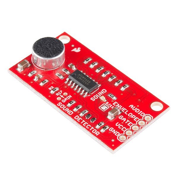
There are three connections on the board:
- Audio - This is the raw audio from the microphone.
- Envelope - This is a analog value representing the volume of the ambient sound.
- Gate - This is a digital value representing if sound levels are low or high.
Wiring
There are two options for wiring, you can use both at the same time:
Digital
Wired up in digital mode the sound detector signals if the sound level is low with a LOW signal, and high with a HIGH signal.
This method requires:
- Power (VCC to 5V)
- Ground (GND to GND)
- Gate to a digital pin on the Arduino (yellow wire in the diagram)
There are three wires:
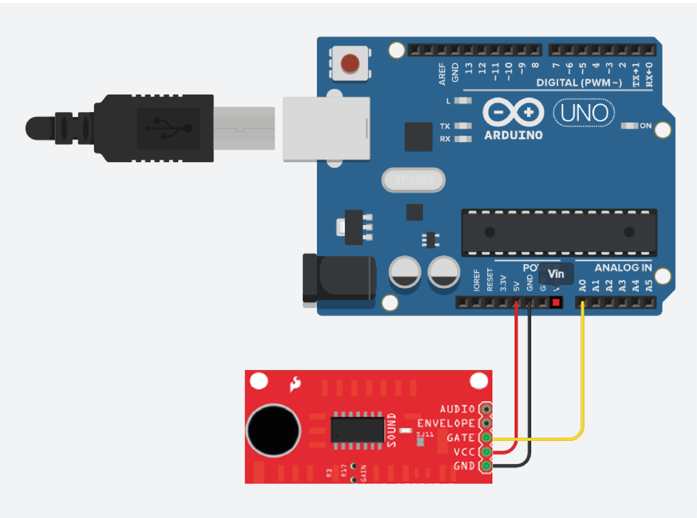
Analog
Wired up in analog mode the sound detector provides voltage proportional to the sound level.
This method requires:
- Power (VCC to 5V)
- Ground (GND to GND)
- Envelope to a analog pin on the Arduino (turquoise wire in the diagram)
There are three wires:
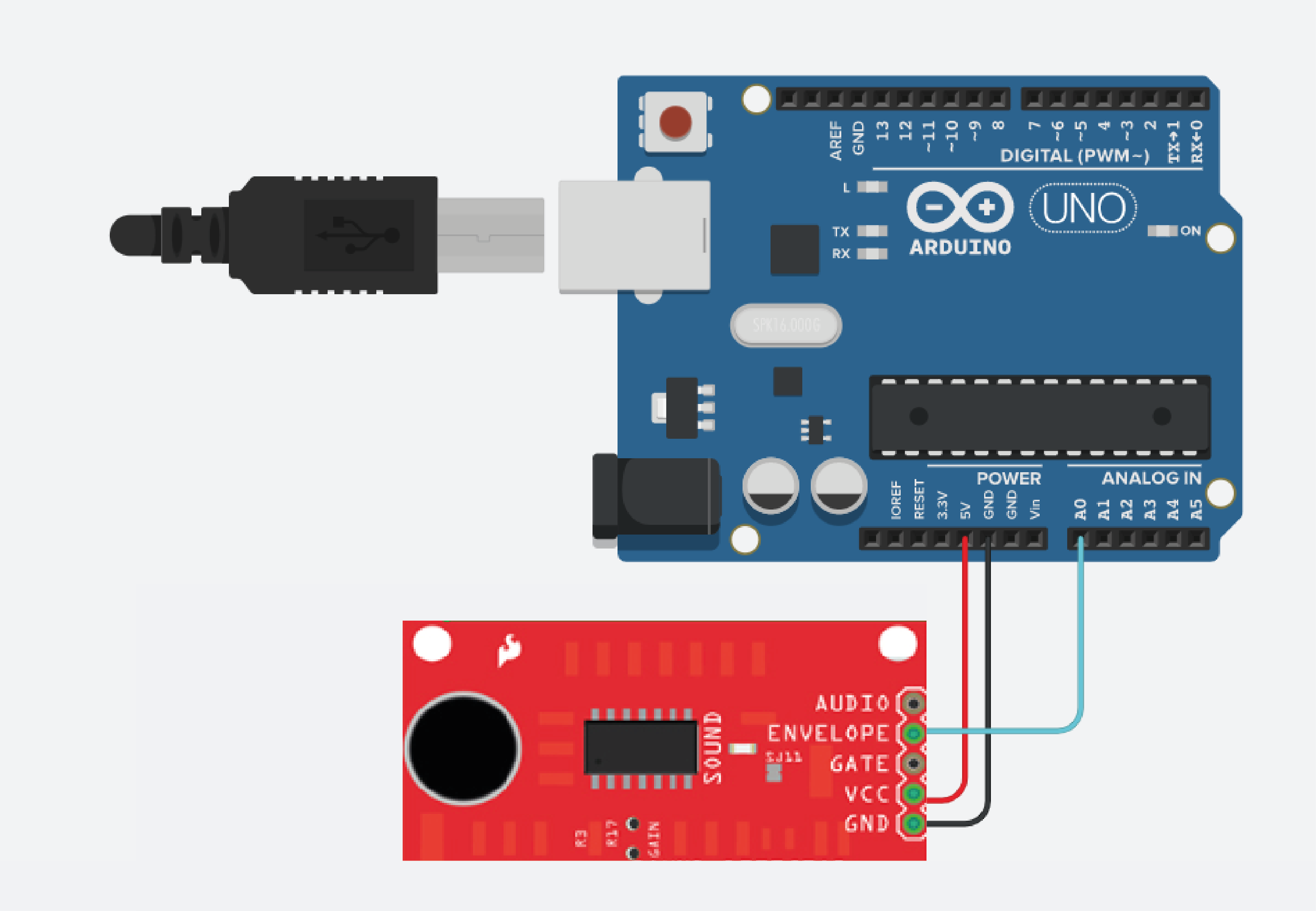
Getting started
Once wired, the code is that of a standard digitalRead or analogRead to obtain the value.
Example code reading envelope
#define envelopePin A0
void setup() {
Serial.begin( 9600 );
pinMode( envelopePin, INPUT );
}
void loop() {
Serial.println( analogRead( envelopePin ) );
}
Example code reading gate
#define gatePin 2
void setup() {
Serial.begin( 9600 );
pinMode( gatePin, INPUT );
}
void loop() {
Serial.println( digitalRead( gatePin ) );
}
Resources
Using a TCS34725 RGB Color Sensor
What is the TCS34725 RGB Color Sensor?
The TCS3472 sensor provides a digital return of red, green, blue (RGB), and clear light sensing values. An RGB Color sensor helps you accurately detect an object’s colour in your Arduino projects.
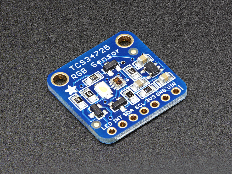
What is I2C?
The TCS34725 has an I2C interface (SDA and SCL) that connects to the Arduino Board. The IC also has an optional interrupt output pin which can be used to interrupt Arduino.
I2C stands for Inter-Integrated Circuit. It is a bus interface connection protocol incorporated into devices for serial communication. I2C Communication Protocol uses only 2 bi-directional open-drain lines for data communication called SDA and SCL. Both these lines are pulled high. Each data bit transferred on SDA line is synchronized by a high to the low pulse of each clock on the SCL line.
- Serial Data (SDA) – Transfer of data takes place through this pin.
- Serial Clock (SCL) – It carries the clock signal.
I2C on different Arduino boards
The two major models you can find in Creative Technology Lab are UNO and LEONARDO. Both have I2C function but have a different pinout. For UNO, the SDA pin is A4 and SCL pin is A5. For LEONARDO, the SDA pin is SDA(pin 20) and SCL pin is SCL(pin 21).
Not every Arduino model has I2C function and not all of them have the same pinout. Check the model before you hook it up with the TCS34725 sensor. Learn more
Library
Adafruit TCS34725 will be used for this tutorial. We have a tutorial on how to install a library here.
Wiring
For LEONARDO, it's more like matching labels.
- GND - GND
- VIN - 5V
- SDA - SDA
- SCL - SCL
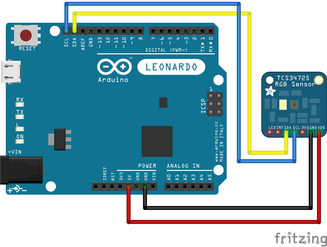
For UNO, A4 and A5 are the I2C pins rather than just a Analog Input pin.
- GND - GND
- VIN - 5V
- SDA - A4
- SCL - A5

Getting started
After installing the library and wiring the board, go ahead and use the examples in the File > Examples > Adafruit TCS34725 menu in Arduino, the tcs34725 example is particularly good as it's simple to check it's working.
Doing more
There is an example in the library for Arduino and Processing which can control the background colour using the colour sensor values.
- In the File > Examples > Adafruit TCS34725 >
colorviewin Arduino IDE, upload to Arduino. - In the File > Examples > Adafruit TCS34725 > examples_processing >
colorviewin Arduino IDE, copy and paste in a Processing sketch.
Serial Port
Before you run the code in Processing, we have to set up the serial port for the communication between Arduino and Processing. Go to line 15.
port = new Serial(this, "COM20", 9600);
"COM20" is the name of the serial port, every USB port on everyone's computer is different. Replace "COM20" with your own port name. For me, my port name is "/dev/cu.usbmodem14601" so I changed the code like this.
port = new Serial(this, "/dev/cu.usbmodem14601", 9600);
You can find your port name at the bottom of your Arduino IDE or go to Tools > Port > ########(Arduino #####).
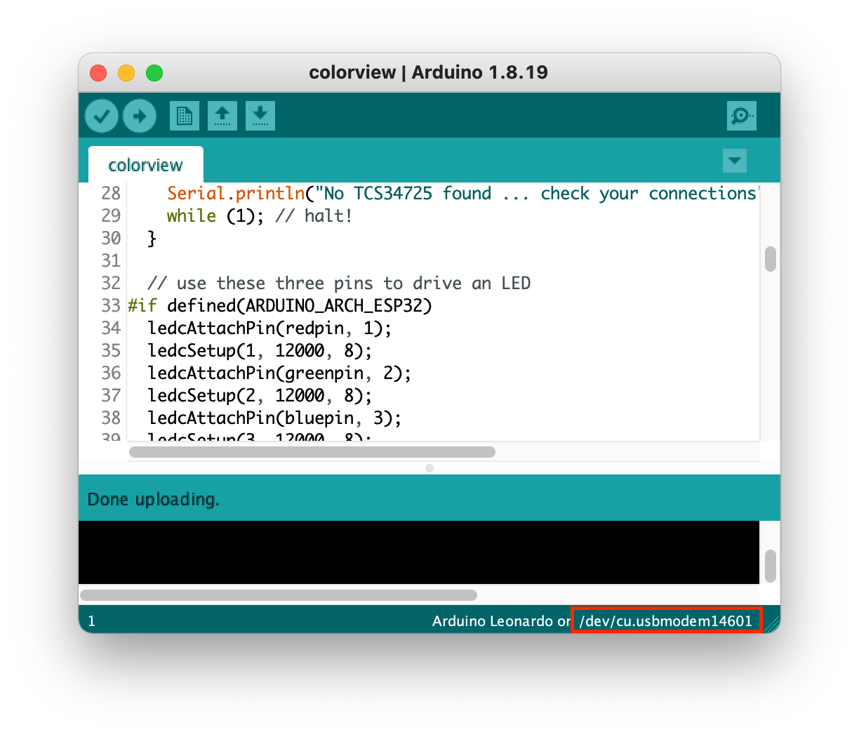
Using a Vibration Motor
What is a vibration motor?
Vibration motor is a DC motor in a compact size that is used to inform the users by vibrating on receiving signals. It is commonly found inside a mobile phone. The one that is available in the lab is coin vibration motor.
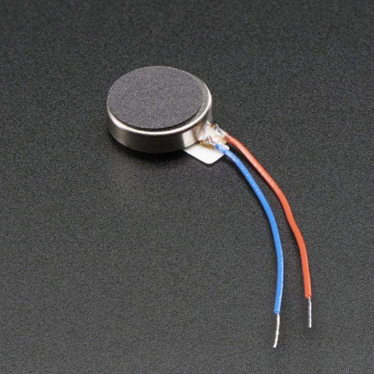
It requires more currnet than an Arduino pin can provide, so a transistor is needed to switch the motor current on and off. Any NPN transistor can be used. In this tutorial, we are using 2N2222. The diode acts as a surge protector against voltage spikes that the motor may produce. The 0.1µF capacitor absorbs voltage spikes produced when the brushes, which are contacts connecting electric current to the motor windings, open and close. To make sure that not too much current flow from the output of the transistor, we place a 1KΩ (or up to 5KΩ) in series with the base of the transistor.
Wiring
These are the electronics used in the circuit.
- vibration motor
- 2N2222 transistor (or any other NPN transistor)
- 0.1µF capacitor
- 1N4001 diode
- 1KΩ resistor
It is a quite complex circuit but try your best to follow!
Other NPN transistors
You can use other NPN transistors for this tutorial, BUT, they may have a different pinout with 2N2222. Check the pinout of your transistor and make sure the pins go as the following.
1. Emitter (E) to Ground (GND)
2. Base (B) to Data pin (pin 3) with 1KΩ resistor
3. Collector (C) to Ground of the actuator (black wire of the motor)
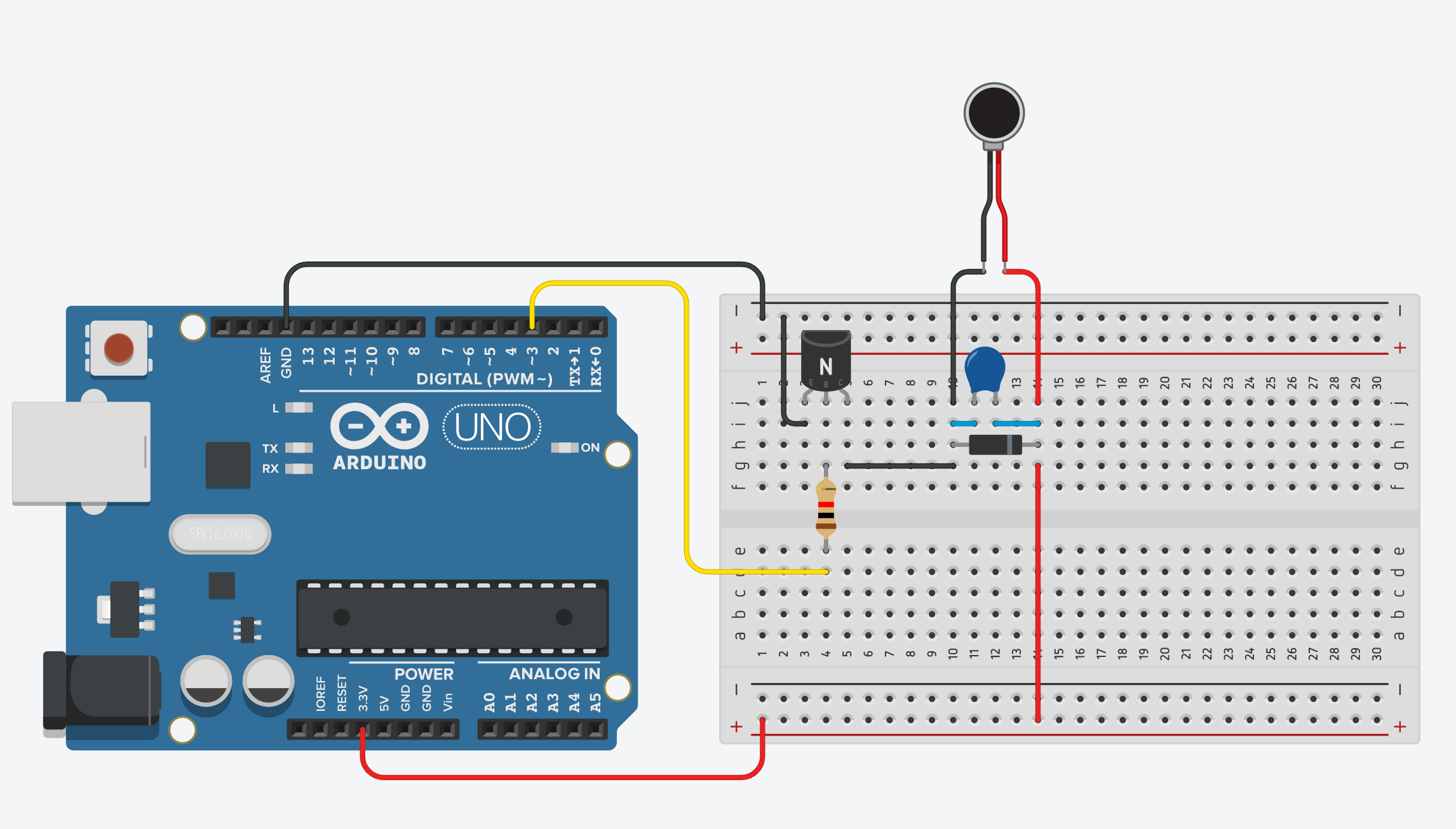
Getting started
This code is getting the motor to vibrate for 1 second and stop for 1 second.
int motorPin = 3; //motor transistor is connected to pin 3
void setup()
{
pinMode(motorPin, OUTPUT);
}
void loop()
{
digitalWrite(motorPin, HIGH); //vibrate
delay(1000); // delay one second
digitalWrite(motorPin, LOW); //stop vibrating
delay(1000); //wait 50 seconds.
}
Using an MFRC522 RFID reader
What is an MFRC522 RFID reader
RFID means radio-frequency identification. RFID uses electromagnetic fields to transfer data over short distances. RFID is useful to identify people, to make transactions, etc…
You can use an RFID system to open a door. For example, only the person with the right information on his card is allowed to enter. An RFID system uses tags with each identification and a two-way radio transmitter-receiver as a reader.
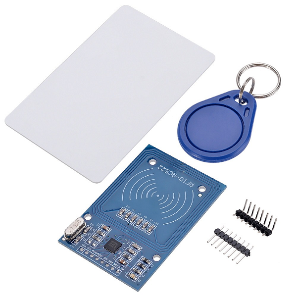
Wiring
Caution
You must power this device to 3.3V! This tutorial is based on Arduino UNO, if you are using a different module, please check the specific pinout of that model.
- SDA - Digital 10 (SS)
- SCK - Digital 13 (SCK)
- MOSI - Digital 11 (MOSI)
- MISO - Digital 12 (MISO)
- IRQ (unconnected)
- GND - GND (Ground)
- RST - Digital 9
- 3.3V to 3.3V (Power)
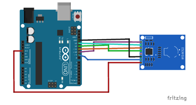
Library
We will be using the MFRC522 library. Please see this tutorial to learn how to install libraries.
Getting started
We will be using the example code, DumpInfo, from the library to read an RFID Tag.
#include <SPI.h>
#include <MFRC522.h>
#define RST_PIN 9 // Configurable, see typical pin layout above
#define SS_PIN 10 // Configurable, see typical pin layout above
MFRC522 mfrc522(SS_PIN, RST_PIN); // Create MFRC522 instance
void setup() {
Serial.begin(9600); // Initialize serial communications with the PC
while (!Serial); // Do nothing if no serial port is opened (added for Arduinos based on ATMEGA32U4)
SPI.begin(); // Init SPI bus
mfrc522.PCD_Init(); // Init MFRC522
delay(4); // Optional delay. Some board do need more time after init to be ready, see Readme
mfrc522.PCD_DumpVersionToSerial(); // Show details of PCD - MFRC522 Card Reader details
Serial.println(F("Scan PICC to see UID, SAK, type, and data blocks..."));
}
void loop() {
// Reset the loop if no new card is present on the sensor/reader. This saves the entire process when idle.
if ( ! mfrc522.PICC_IsNewCardPresent()) {
return;
}
// Select one of the cards
if ( ! mfrc522.PICC_ReadCardSerial()) {
return;
}
// Dump debug info about the card; PICC_HaltA() is automatically called
mfrc522.PICC_DumpToSerial(&(mfrc522.uid));
}
We will be using the example code, DumpInfo, from the library to read an RFID Tag.
Touch sensor - Using an MPR121
What is the MPR121?
The MPR121 is a tiny microchip formerly manufactured by NXP, now under Resurgent Semiconductor, it is a tiny surface mount device that provides 12 capacitive touch electrodes through an I2C interface. We are using Adafruit MPR121 in this tutorial.
What is capacitive touch?
Capacitive touch the the technology used on modern touch sensitive devices such as phone and tablet screens, trackpads and computer mice like Apple's Magic Mouse.
Capacitive touch takes advantage of the human body being electrically conductive, this is why using a pen on a smart phone doesn't work and styluses for these devices are made of metal so they will make an electrical connection.
Capacitive touch is relatively complex to understand but fundamentally the sensor can detect when you are in proximity or actually touching the electrode, or any conductive part between the chip and the end of the wire.
If you extend a wire from the electrode, even if it is shielded with plastic, it will probably detect you touching the wire just the same as the exposed metal part.
Adafruit MPR121
- Power input: 3.3V to 5V
- Address: 0x5A, it is also relatively easy to configure the address to 0x5B, 0x5C or 0x5D allowing up to 48 electrodes (12 x 4).
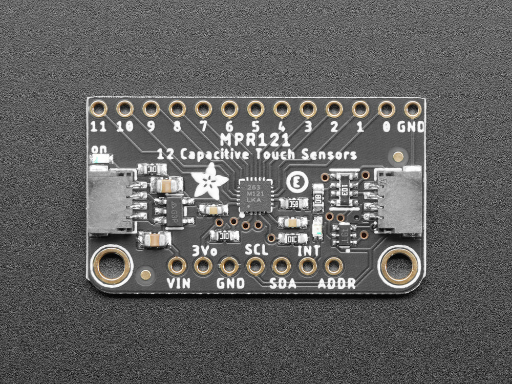
Library
Adafruit, Sparkfun, Seeedstudio and Bare Conductive all provide Arduino libraries, however by far the best which includes tools for visualising the data is the Bare Conductive Touch Board library and grapher. All libraries should all work interchangeably as long as you get the correct address and IRQ pin.
The key thing to remember when using examples from the Bare Conductive library is that they use the address 0x5C rather than the default 0x5A address used on both the Sparkfun and Adafruit boards, also ensure that you use the correct IRQ pin based on the example you are using.
We have a tutorial on how to install a library here.
Wiring
Wiring is pretty simple, it's an I2C component so it's relatively standard.
- VIN -> 5V
- GND -> GND
- SCL -> SCL / A5
- SDA -> SDA / A4
Older Arduino boards
Some older Arduino boards do not have SDA and SCL pins as shown in the diagrams, in this case you'll need to look it up on the boards documentation, however most Arduino boards used A4 as SDA and A5 as SCL.
Getting started
After installing the library and wiring the board, go ahead and use the examples in the File > Examples menu in Arduino, the Simple Touch example is particularly good as it's simple to check it's working.
Basic Example
This is a basic example of using the MPR121 with the Bare Conductive MPR121 library to show which touch point is touched.
#include <MPR121.h>
#include <Wire.h>
#define numElectrodes 12
void setup() {
Serial.begin(9600);
Wire.begin();
// Setup MPR121
MPR121.begin(0x5A);
MPR121.setInterruptPin(4);
MPR121.setTouchThreshold(20); //0 (most sensitive) to 255 (least sensitive)
MPR121.setReleaseThreshold(10); //half of TouchThreshold
}
void loop() {
// Update touch data
MPR121.updateTouchData();
// Loop through all electrodes
for (int i = 0; i < numElectrodes; i++) {
if (MPR121.getTouchData(i)) {
Serial.print("Touched electrode: ");
Serial.println(i);
}
}
delay(100); // Small delay to reduce serial output frequency
}
Getting proximity / raw data
This example code is only reading from electrode 11.
#include <MPR121.h>
#include <Wire.h>
void setup() {
Serial.begin(9600);
Wire.begin();
// Initialize MPR121
MPR121.begin(0x5A); // Default I2C address
MPR121.setTouchThreshold(40);
MPR121.setReleaseThreshold(20);
}
void loop() {
// Update sensor readings
MPR121.updateTouchData();
MPR121.updateFilteredData();
// Print filtered data for electrode 11
Serial.print("FilteredData[11]: ");
Serial.println(MPR121.getFilteredData(11));
delay(100); // Adjust for readability
}
CSV Example
This is an example using the MPR121 with the Bare Conductive MPR121 library to output each electrode's touch status to the serial port as a comma separated string.
This example can be modified to work with MaxMSP easily by changing the delimiter line to a space instead of a comma:
#define DELIMITER " "
You could also modify this example to output the proximity data, instead of the touch data by modifying the updateTouchData line to:
MPR121.updateFilteredData();
And the getTouchData line to:
Serial.print( MPR121.getFilteredData( i ) );
Touch sensor - Using an CAP1188
What is the CAP1188?
The CAP1188 is an easy-to-use 8-channel capacitive touch sensor breakout board. This chip can handle up to 8 individual touch pads, it will light up the 8 onboard LEDs when the matching touch sensor fires to help you debug your sensor setup.
The CAP1188 has support for both I2C and SPI, so it easy to use with any microcontroller. If you are using I2C, you can select one of 5 addresses, for a total of 40 capacitive touch pads on one I2C 2-wire bus. Using this chip is a lot easier than doing the capacitive sensing with analog inputs: it handles all the filtering for you and can be configured for more/less sensitivity.

Other Capacitive Touch Sensing Method
We have tutorials for other alternatives as well!
MPR121 vs CAP1188 Comparison
| Feature | MPR121 | CAP1188 |
|---|---|---|
| Number of Inputs | 12 electrodes | 8 electrodes |
| Multi-touch | ✅ Yes (tracks all touches) | ⚠️ Partial (multi-touch disabled by default) |
| I2C Addressability | 4 possible addresses (0x5A–0x5D) | 3 jumpers for I2C address config |
| Proximity Sense | ✅ Yes (via filtered data) | ✅ Yes (via built-in proximity detection) |
| Slider/Wheel Support | ✅ Yes | ❌ Not native |
| Sensitivity Adjustments | ✅ Touch & release thresholds | ✅ Built-in auto-calibration, less customizable |
| Interrupt Support | ✅ Yes | ✅ Yes |
| Noise Handling | Good, needs tuning | Excellent built-in debounce and filtering |
| Communication | I2C | I2C or SPI (selectable) |
| Power Consumption | Low | Low |
Library
We will be using the library Adafruit CAP1188.
We have a tutorial on how to install a library here.
Wiring
Wiring is pretty simple, it's an I2C component so it's relatively standard.
- VIN -> 5V
- GND -> GND
- SCL -> SCL / A5
- SDA -> SDA / A4
Older Arduino boards
Some older Arduino boards do not have SDA and SCL pins as shown in the diagrams, in this case you'll need to look it up on the boards documentation, however most Arduino boards used A4 as SDA and A5 as SCL.
Getting started
After installing the library and wiring the board, go ahead and use the examples in the File > Examples > Adafruit CAP1188> cap1188test.
Using an PN532 RFID reader
What is the difference between an PN532 RFID reader and an MFRC522 RFID reader
The PN532 and MFRC522 are two popular RFID reader modules, each with its own features and use cases.

| Feature | PN532 | MFRC522 | Which Better |
|---|---|---|---|
| Communication | SPI, I2C, UART | SPI only | ✔ PN522 |
| Supported Protocols | NFC, RFID (13.56 MHz) | RFID (13.56 MHz) | ✔ PN522 |
| Standards | ISO14443A/B, FeliCa | ISO14443A (MIFARE) | ✔ PN522 |
| Range | ~10 cm | ~5 cm | ✔ PN522 |
| Cost | Higher (~$10–$30) | Lower (~$2–$10) | ✔ MFRC522 |
| Power | Higher | Lower | ✔ MFRC522 |
| Applications | Advanced, NFC, IoT | Basic RFID projects | ✔ PN522 |
In this tutorial, we will be using a PN532 module from DFRobot, if you are using an MFRC522 module, please refer to this tutorial. This tutorial is adapted from here.
RFID Tag
Aside from the regular card, there are more options than before, including stickers, button tags etc.

Wiring
Switch
This tutorial will be using the i2c communication protocol, make sure you switch to IIC on the module.
- D/T - SDA (Pin 14)
- C/R - SCL (Pin 15)
- GND - GND (Ground)
- VCC to 5V (Power)

Library
We will be using the DFRobot_PN532 library. Please see this tutorial to learn how to install libraries.
Getting started
The number of blocks of data depends on the type of RFID tag or card you’re using. Most commonly, the MIFARE Classic card is used, which is compatible with both the PN532 and MFRC522. A standard MIFARE Classic 1K card will have 64 blocks of data and the smaller NTAG213 tag will have 36 blocks of data.
Some blocks are read-only, so you cannot write data to those blocks. For example, Block 0 usually contains the UID (Unique Identifier) and other manufacturer data, and is read-only.
The below codes are only for writing to and reading the data from Block 3.
Write Data
#include <DFRobot_PN532.h>
#define BLOCK_SIZE 16
#define PN532_IRQ 2
#define INTERRUPT 1
#define POLLING 0
// The block to be written
#define WRITE_BLOCK_NO 3
DFRobot_PN532_IIC nfc(PN532_IRQ, POLLING);
uint8_t dataWrite[BLOCK_SIZE] = {"your message"}; //change to your data
void setup() {
Serial.begin(115200);
Serial.print("Initializing");
while (!nfc.begin()) {
Serial.print(".");
delay (1000);
}
Serial.println();
Serial.println("Waiting for a card......");
}
void loop() {
// For S50 card/tag, block 1-2, 4-6, 8-10, 12-14... 56-58, 60-62 are for user data
// You can read/write these blocks freely.
// Use "MifareClassic_ReadAllMemory.ino" to check all the blocks
if (nfc.scan()) {
if (nfc.writeData(WRITE_BLOCK_NO, dataWrite) != 1) {
Serial.print("Block ");
Serial.print(WRITE_BLOCK_NO);
Serial.println(" write failure!");
}
else {
Serial.print("Block ");
Serial.print(WRITE_BLOCK_NO);
Serial.println(" write success!");
Serial.print("Data written(string):");
Serial.println((char *)dataWrite);
Serial.print("Data written(HEX):");
for (int i = 0; i < BLOCK_SIZE; i++) {
Serial.print(dataWrite[i], HEX);
Serial.print(" ");
}
}
}
delay(500);
}
Read Data
#include <DFRobot_PN532.h>
#define BLOCK_SIZE 16
#define PN532_IRQ 2
#define INTERRUPT 1
#define POLLING 0
// The block to be read
#define READ_BLOCK_NO 3
DFRobot_PN532_IIC nfc(PN532_IRQ, POLLING);
uint8_t dataRead[16] = {0};
void setup() {
pinMode(13,OUTPUT);
Serial.begin(115200);
Serial.print("Initializing");
while (!nfc.begin()) {
Serial.print(".");
delay (1000);
}
Serial.println();
Serial.println("Waiting for a card......");
}
void loop() {
// For S50 card/tag, block 1-2, 4-6, 8-10, 12-14... 56-58, 60-62 are for user data
// You can read/write these blocks freely.
// Use "MifareClassic_ReadAllMemory.ino" to check all the blocks
if (nfc.scan()) {
if (nfc.readData(dataRead, READ_BLOCK_NO) != 1) {
Serial.print("Block ");
Serial.print(READ_BLOCK_NO);
Serial.println(" read failure!");
}
else {
Serial.print("Block ");
Serial.print(READ_BLOCK_NO);
Serial.println(" read success!");
Serial.print("Data read(string):");
String data = (char *)dataRead;
Serial.println(data);
/*
//interaction
if(data == "your message" ){
digitalWrite(13, HIGH);
}else{
digitalWrite(13, LOW);
}
*/
/*
//in hex
Serial.print("Data read(HEX):");
for (int i = 0; i < BLOCK_SIZE; i++) {
Serial.print(dataRead[i], HEX);
Serial.print(" ");
dataRead[i] = 0;
}
Serial.println();
*/
}
delay(500);
}
}
NTAG203
If you are using a NTAG203 sticker, you will need to use the Adafruit_PN532 library instead.
Write Data
#include <Wire.h>
#include <Adafruit_PN532.h>
#define SDA_PIN SDA
#define SCL_PIN SCL
#define WRITE_PAGE_NO 4 // Change this to the correct writable page
Adafruit_PN532 nfc(SDA_PIN, SCL_PIN);
uint8_t dataWrite[4] = {'T', 'E', 'S', 'T'}; // Must be 4 bytes for NTAG203
void setup() {
Serial.begin(115200);
nfc.begin();
uint32_t versiondata = nfc.getFirmwareVersion();
if (!versiondata) {
Serial.println("PN532 not found!");
while (1);
}
nfc.SAMConfig();
Serial.println("Waiting for an NFC card...");
}
void loop() {
uint8_t uid[] = {0, 0, 0, 0, 0, 0, 0}; // Store UID
uint8_t uidLength;
if (nfc.readPassiveTargetID(PN532_MIFARE_ISO14443A, uid, &uidLength)) {
Serial.println("NFC tag detected!");
if (nfc.ntag2xx_WritePage(WRITE_PAGE_NO, dataWrite)) {
Serial.println("Write successful!");
} else {
Serial.println("Write failed!");
}
delay(2000); // Avoid continuous writes
}
}
Read Data
#include <Wire.h>
#include <Adafruit_PN532.h>
#define SDA_PIN SDA
#define SCL_PIN SCL
#define READ_PAGE_NO 4 // Change this to the page you want to read
Adafruit_PN532 nfc(SDA_PIN, SCL_PIN);
void setup() {
Serial.begin(115200);
nfc.begin();
uint32_t versiondata = nfc.getFirmwareVersion();
if (!versiondata) {
Serial.println("PN532 not found!");
while (1);
}
nfc.SAMConfig();
Serial.println("Waiting for an NFC tag...");
}
void loop() {
uint8_t uid[] = {0, 0, 0, 0, 0, 0, 0}; // To store the tag UID
uint8_t uidLength;
if (nfc.readPassiveTargetID(PN532_MIFARE_ISO14443A, uid, &uidLength)) {
Serial.println("NFC tag detected!");
uint8_t dataRead[4]; // NTAG203 pages are 4 bytes each
if (nfc.ntag2xx_ReadPage(READ_PAGE_NO, dataRead)) {
Serial.print("Data at Page ");
Serial.print(READ_PAGE_NO);
Serial.print(": ");
// Print as ASCII characters
for (int i = 0; i < 4; i++) {
Serial.print((char)dataRead[i]);
}
Serial.print(" (HEX: ");
for (int i = 0; i < 4; i++) {
Serial.print(dataRead[i], HEX);
Serial.print(" ");
}
Serial.println(")");
} else {
Serial.println("Read failed!");
}
delay(2000); // Avoid continuous reads
}
}
Using Arduino Leonardo to send USB MIDI data
One of the secrets of Arduino Leonardo is the in-built USB MIDI support.
This is really useful for sending data from Arduino to applications like MadMapper, Max and Ableton Live.
In order to use this you'll need to follow the guide on How to install libraries to install the MIDIUSB library.
The following is a modification of the basic MIDIUSB write example, by wrapping the noteOn and noteOff code in logic you could attach this to a button or sensor.
#include "MIDIUSB.h"
void setup() {
Serial.begin(115200);
}
void loop() {
Serial.println("Sending note on");
noteOn(0, 48, 64); // Channel 0, middle C, normal velocity
MidiUSB.flush();
delay(500);
Serial.println("Sending note off");
noteOff(0, 48, 64); // Channel 0, middle C, normal velocity
MidiUSB.flush();
delay(1500);
// controlChange(0, 10, 65); // Set the value of controller 10 on channel 0 to 65
}
void noteOn(byte channel, byte pitch, byte velocity) {
midiEventPacket_t noteOn = {0x09, 0x90 | channel, pitch, velocity};
MidiUSB.sendMIDI(noteOn);
}
void noteOff(byte channel, byte pitch, byte velocity) {
midiEventPacket_t noteOff = {0x08, 0x80 | channel, pitch, velocity};
MidiUSB.sendMIDI(noteOff);
}
void controlChange(byte channel, byte control, byte value) {
midiEventPacket_t event = {0x0B, 0xB0 | channel, control, value};
MidiUSB.sendMIDI(event);
}
Using AVR ISP MKII to upload firmware to Arduino
What is AVR ISP MKII?
The AVRISP mkII is a USB-based In-System Programmer (ISP) used to program Atmel (now Microchip) AVR microcontrollers. It's designed for developers and hobbyists to upload firmware to AVR-based chips directly on a circuit board without needing to remove the chip.
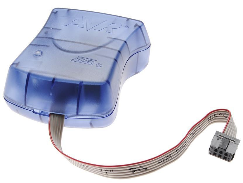
In this tutorial, we will burn the bootloader to an Arduino UNO (re-upload the firmware to the ATmega328P chip on UNO).
Supported Microcontrollers
It is compatible with a wide range of AVR microcontrollers, including the popular ATmega and ATtiny series.
- Arduino Uno
- Arduino Nano
- Arduino Leonardo
- Arduino Mega 2560
However, it is not compatible with microcontrollers with ARM-based chips or ESP microcontrollers, such as
- Arduino Due
- Arduino Zero
- Arduino MKR series
- Arduino Nano 33 series
Software Compatibility
Works with Atmel Studio (formerly AVR Studio), Arduino IDE and other tools supporting AVR programming. In this tutorial, we will be using Arduino IDE.
Connection
- AVR ISP MKII to the computer using USB B cable
- 5V power supply for Arduino UNO (target Arduino), can be via USB port
- AVR ISP MKII 6-pin connector to Arduino ICSP pins (at the bottom usually)
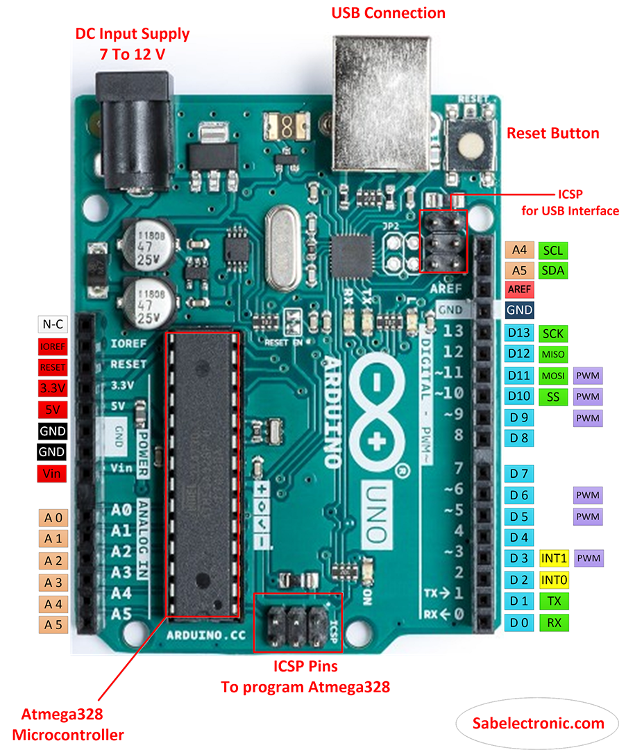
Status LEDs
General speaking, Green = Everything is OK. Red = There is an issue.
Below is some common examples:
Everything works fine:
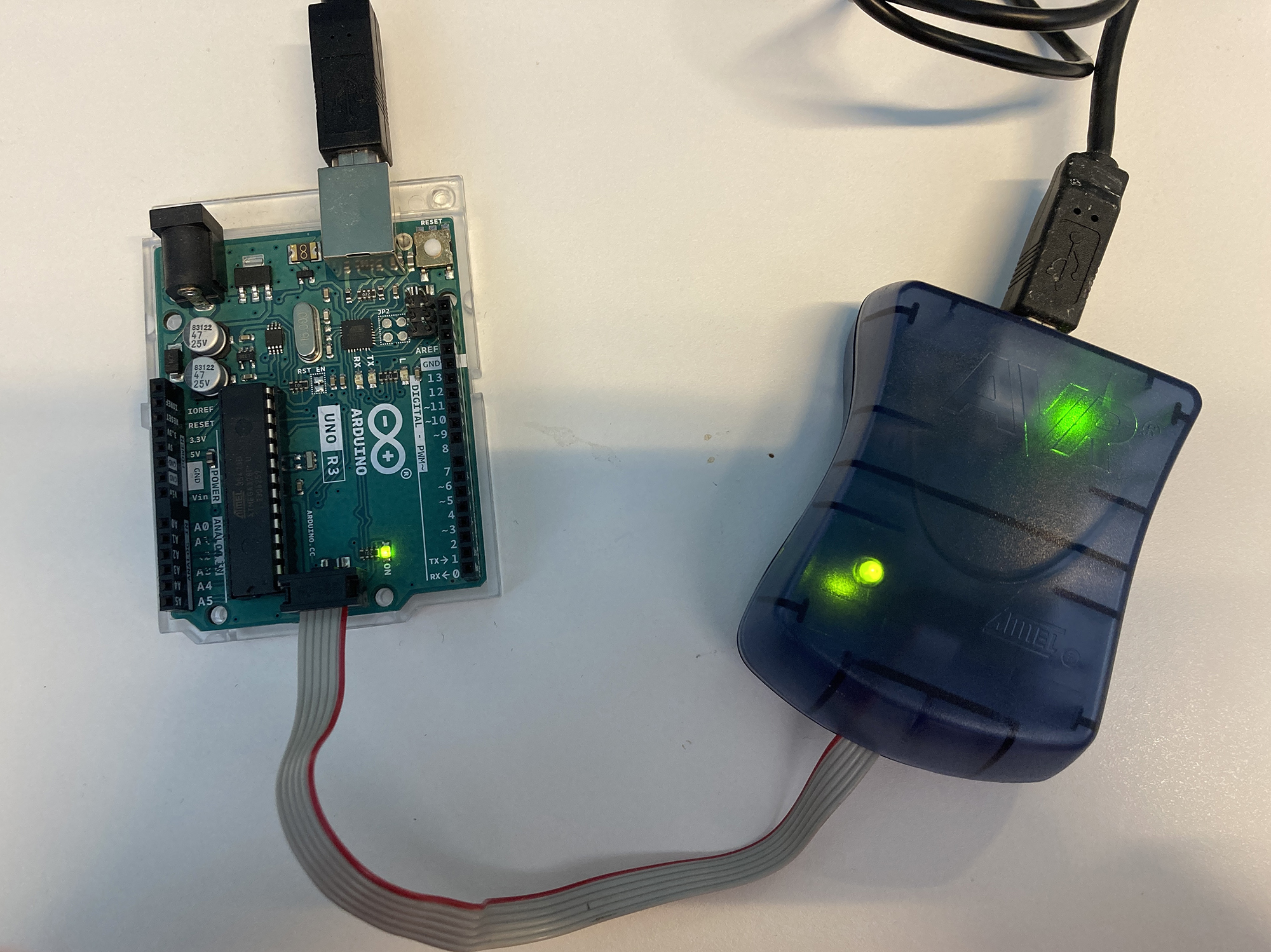
Missing power supply for target Arduino:
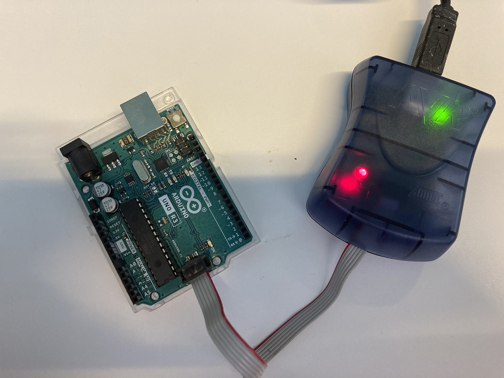
6-pin connection wrong direction:
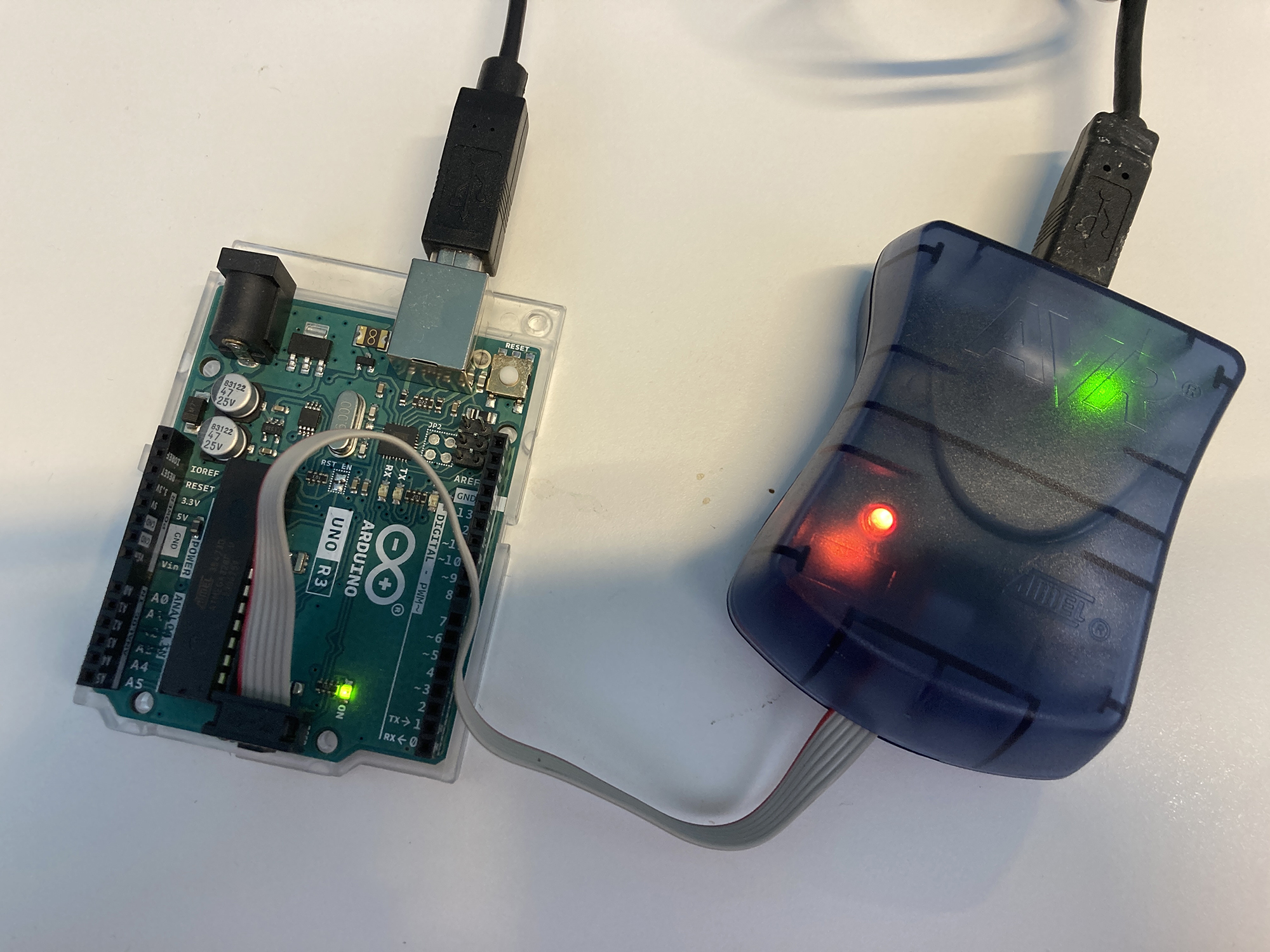
Burn bootloader with Arduino IDE
-
Board: Choose your target Arduino - Leave the
Portempty - Click
Burn Bootloader - Done!
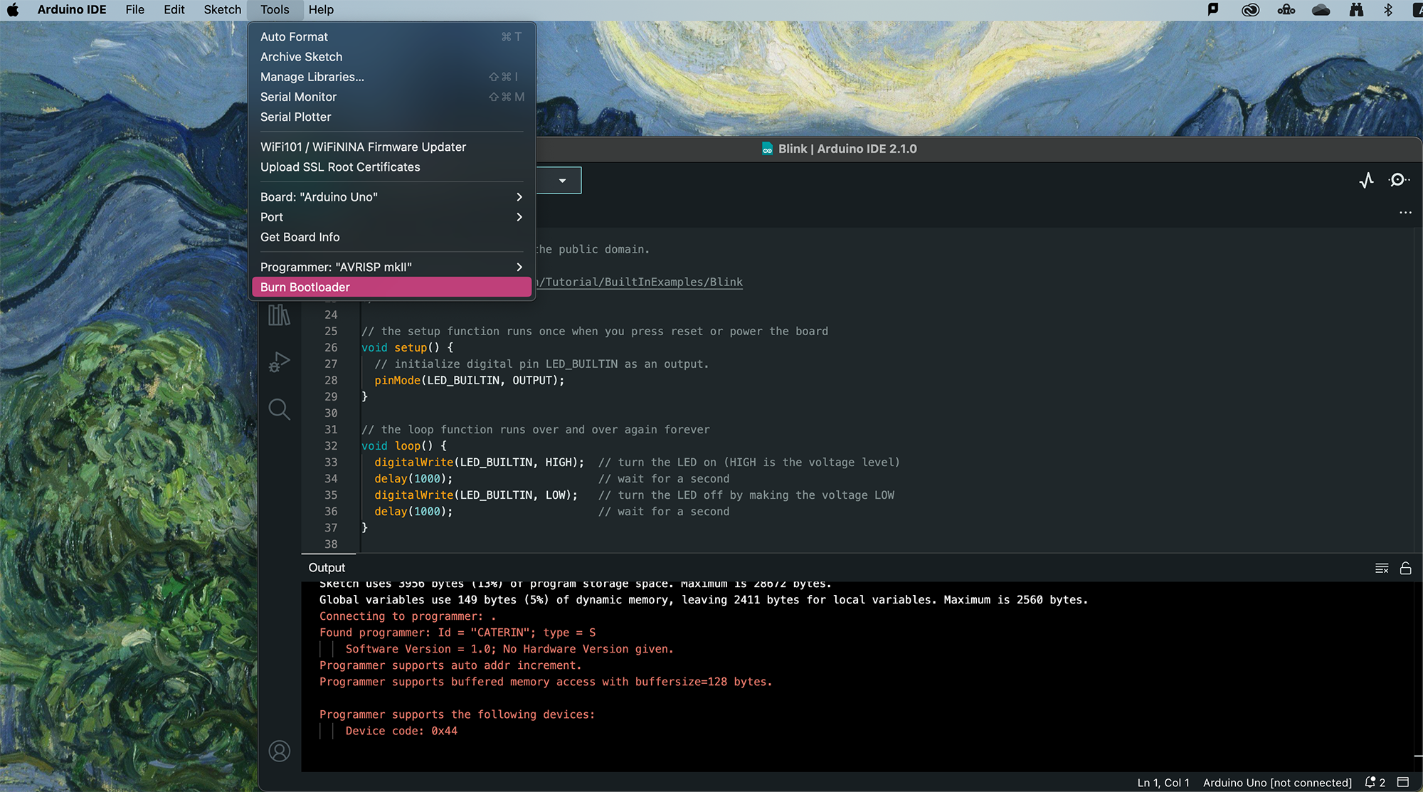
Using L293D IC for motors
What is L293D?
The L293D is a 16-pin Motor Driver IC which can control a set of two DC motors simultaneously in any direction. The L293D is designed to provide bidirectional drive currents of up to 600 mA (per channel) at voltages from 4.5 V to 36 V. It can be extremely hot. When they get overheated, they may not follow commands anymore.
It is cheap but may not have the easiest pinout to read for beginners.
DC motor
DC motor is very common to be found in toys. It usually comes with 2 wires, one red(+) and one black(-).

Although it can be small and cheap, it can be very fast. Therefore sometimes it comes with a gearbox which will slow down the speed of the motor.

Taking a 12V DC motor for example, we connect the red wire of the motor to the positive wire of the power supply and the black wire of the motor to the negative wire of the power supply as normal practice. We will get a motor running clockwise at full speed.

BUT if we reverse the red and black wires of the motor we connect the black wire of the motor to the positive wire of the power supply and the red wire of the motor to the negative wire of the power supply. We will get a motor running anti-clockwise at full speed.

Wiring
Be careful with which pin on the IC to which pin on the Arduino as there are 16 pins you need to connect!

Pinout of L293D

You may not understand what these labels stand for. Let's look at the below one, you can see where they are actually connected to and what they do.

As said earlier, the DC motor changes direction by reversing the + wire and - wire. If you reverse Motor A (+) (Pin3 of IC) and Motor A (-)(Pin6 of IC), the Pin2 of IC (Arduino Pin 5) will be the Clockwise control and the Pin7 of IC (Arduino Pin 6) will be the Anti-clockwise control.
You do not have to strictly follow which digital pins on Arduino to be used, as long as you match the number of pins in the code. And you will need to use PWM(~) pins for both speed control pins on the IC (IC pin1 & 9).
Get started
This example code will let you test the directions of the motors and has custom functions for forward(), backward(), stop(), turnRight() and turnLeft().
//L293D
//Motor A
const int motorAspeed = 3;
const int motorPin1 = 5; // Pin 14 of L293
const int motorPin2 = 6; // Pin 10 of L293
//Motor B
const int motorBspeed = 11;
const int motorPin3 = 10; // Pin 7 of L293
const int motorPin4 = 9; // Pin 2 of L293
//This will run only one time.
void setup(){
//Set pins as outputs
pinMode(motorPin1, OUTPUT);
pinMode(motorPin2, OUTPUT);
pinMode(motorPin3, OUTPUT);
pinMode(motorPin4, OUTPUT);
pinMode(motorAspeed, OUTPUT);
pinMode(motorBspeed, OUTPUT);
analogWrite(motorAspeed, 255); //set motor A speed 0-255
analogWrite(motorBspeed, 255); //set motor B speed 0-255
/*
//Motor Control Testing - Motor A: motorPin1,motorpin2 & Motor B: motorpin3,motorpin4
//This code will turn Motor A clockwise for 2 sec.
digitalWrite(motorPin1, HIGH); //5
digitalWrite(motorPin2, LOW);
digitalWrite(motorPin3, LOW);
digitalWrite(motorPin4, LOW);
delay(2000);
//This code will turn Motor A counter-clockwise for 2 sec.
digitalWrite(motorPin1, LOW);
digitalWrite(motorPin2, HIGH); //6
digitalWrite(motorPin3, LOW);
digitalWrite(motorPin4, LOW);
delay(2000);
//This code will turn Motor B clockwise for 2 sec.
digitalWrite(motorPin1, LOW);
digitalWrite(motorPin2, LOW);
digitalWrite(motorPin3, HIGH); //10
digitalWrite(motorPin4, LOW);
delay(2000);
//This code will turn Motor B counter-clockwise for 2 sec.
digitalWrite(motorPin1, LOW);
digitalWrite(motorPin2, LOW);
digitalWrite(motorPin3, LOW);
digitalWrite(motorPin4, HIGH); //9
delay(2000);
//And this code will stop motors
digitalWrite(motorPin1, LOW);
digitalWrite(motorPin2, LOW);
digitalWrite(motorPin3, LOW);
digitalWrite(motorPin4, LOW);
*/
}
void loop(){
forward();
delay(5000);
backward();
delay(5000);
stop();
delay(5000);
turnRight();
delay(5000);
turnLeft();
delay(5000);
}
void forward(){
digitalWrite(motorPin1, HIGH);
digitalWrite(motorPin2, LOW);
digitalWrite(motorPin3, HIGH);
digitalWrite(motorPin4, LOW);
}
void backward(){
digitalWrite(motorPin1, LOW);
digitalWrite(motorPin2, HIGH);
digitalWrite(motorPin3, LOW);
digitalWrite(motorPin4, HIGH);
}
void stop(){
digitalWrite(motorPin1, LOW);
digitalWrite(motorPin2, LOW);
digitalWrite(motorPin3, LOW);
digitalWrite(motorPin4, LOW);
}
void turnRight(){
digitalWrite(motorPin1, HIGH);
digitalWrite(motorPin2, LOW);
digitalWrite(motorPin3, LOW);
digitalWrite(motorPin4, LOW);
}
void turnLeft(){
digitalWrite(motorPin1, LOW);
digitalWrite(motorPin2, LOW);
digitalWrite(motorPin3, HIGH);
digitalWrite(motorPin4, LOW);
}
There is a simulated circuit made in Tinkercad for you to try out!
Using MatrixPortal M4 for animation
How to use MatrixPortal M4 for animation
We have another tutorial for setting up the MatrixPortal board and covering the basics. This tutorial will focus on creating an animation to display on a 64x32 matrix.
CircuitPython and libraries versions
In this tutorial, we are using CircuitPython 9.0.5 (11/10/2024), all libraries and code used are compatible with this version. Please double-check the latest version of CircuitPython you have installed and use updated and compatible libraries.
Creating the Spitesheet
A spritesheet is a single image file that contains a collection of smaller images (called sprites) arranged in a grid or some other layout. These individual sprites can represent various frames of an animation, characters, objects, or other visual elements in a video game or graphic application.
We will need to use a bitmap spitesheet. If you just want to test the code, you can download the test.bmp and skip this part for now.
1. Piskel
Piskel is a free online editor for animated sprites & pixel art.
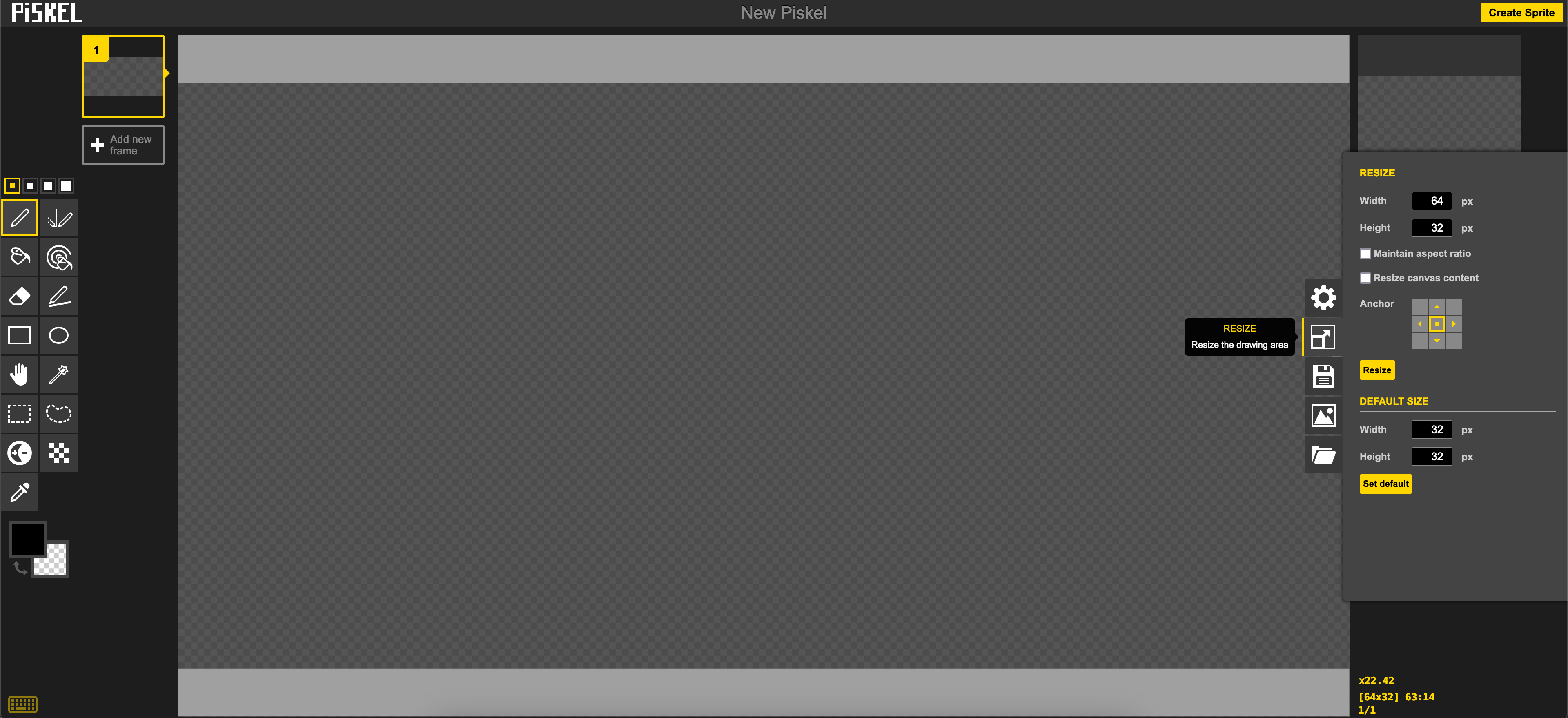
- Go to
resizeto set the canvas size to 64 x 32 px - Draw whatever you want
-
Add new frameand draw - until you finish
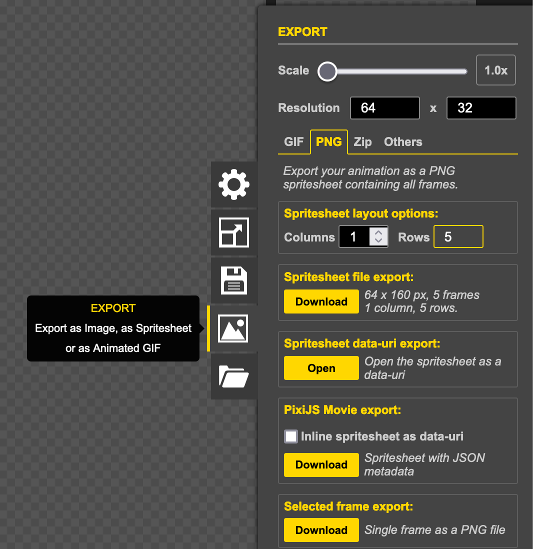
- Go to
EXPORT - Select
PNG - Change
Columnsto 1 -
Download - You now have a very long PNG file
2. Photoshop
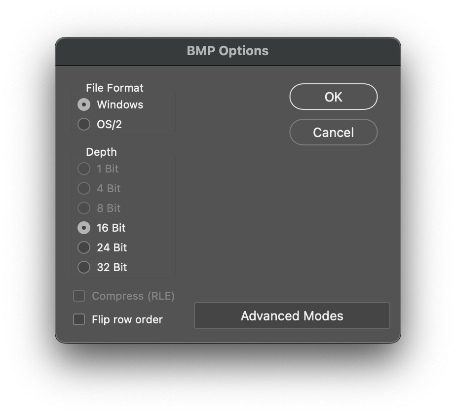
- Open the image with Photoshop
- Save a copy in BMP format
- Choose
Windows(doesn't matter what computer you use) and16 Bit - You now have a ready-to-go spitesheet BMP file
Importing the Image
- Create a folder called
bmpin the CIRCUITPY drive. - Copy the bitmap file you have created into the folder.
Code
# SPDX-FileCopyrightText: 2020 John Park for Adafruit Industries
#
# SPDX-License-Identifier: MIT
import time
import os
import board
import displayio
from digitalio import DigitalInOut, Pull
from adafruit_matrixportal.matrix import Matrix
from adafruit_debouncer import Debouncer
SPRITESHEET_FOLDER = "/bmp"
DEFAULT_FRAME_DURATION = 0.1 # 100ms
FRAME_DURATION_OVERRIDES = {
"KIRBY.bmp": 0.05,
}
# --- Display setup ---
matrix = Matrix(width=64, height=64, bit_depth=6)
sprite_group = displayio.Group()
matrix.display.root_group = sprite_group
file_list = sorted(
[
f
for f in os.listdir(SPRITESHEET_FOLDER)
if (f.endswith(".bmp") and not f.startswith("."))
]
)
if len(file_list) == 0:
raise RuntimeError("No images found")
current_image = None
current_frame = 0
current_loop = 0
frame_count = 0
frame_duration = DEFAULT_FRAME_DURATION
direction = 1 #1 for forward, -1 for backward
def load_image():
"""
Load an image as a sprite
"""
# pylint: disable=global-statement
global current_frame, current_loop, frame_count, frame_duration
while sprite_group:
sprite_group.pop()
filename = SPRITESHEET_FOLDER + "/" + file_list[current_image]
# # CircuitPython 7+ compatible
bitmap = displayio.OnDiskBitmap(filename)
sprite = displayio.TileGrid(
bitmap,
pixel_shader=bitmap.pixel_shader,
tile_width=bitmap.width,
tile_height=matrix.display.height,
)
sprite_group.append(sprite)
current_frame = 0
current_loop = 0
frame_count = int(bitmap.height / matrix.display.height)
frame_duration = DEFAULT_FRAME_DURATION
if file_list[current_image] in FRAME_DURATION_OVERRIDES:
frame_duration = FRAME_DURATION_OVERRIDES[file_list[current_image]]
direction = 1
def advance_image():
"""
Advance to the next image in the list and loop back at the end
"""
# pylint: disable=global-statement
global current_image
if current_image is not None:
current_image += 1
if current_image is None or current_image >= len(file_list):
current_image = 0
load_image()
def advance_frame():
"""
Advance to the next frame and loop back at the end
"""
# pylint: disable=global-statement
global current_frame, current_loop, direction
current_frame += direction
if current_frame >= frame_count:
current_frame = frame_count - 1
direction = -1 # Reverse direction
elif current_frame < 0:
current_frame = 0
direction = 1 # Forward direction
sprite_group[0][0] = current_frame
advance_image()
while True:
advance_frame()
time.sleep(frame_duration)
Using the MAX9814 mic amplifier
This Adafruit MAX9814 microphone amplifier allows you to easily detect sound.
There are a total of five connections on this mic, however we will only be using VCC, GND and OUT in our wiring. You can read more about this component here.
Wiring
- Power (VCC to 3.3V)
- Ground (GND to GND)
- Output to analog pin on the Arduino (OUT to A0)
There are three wires:
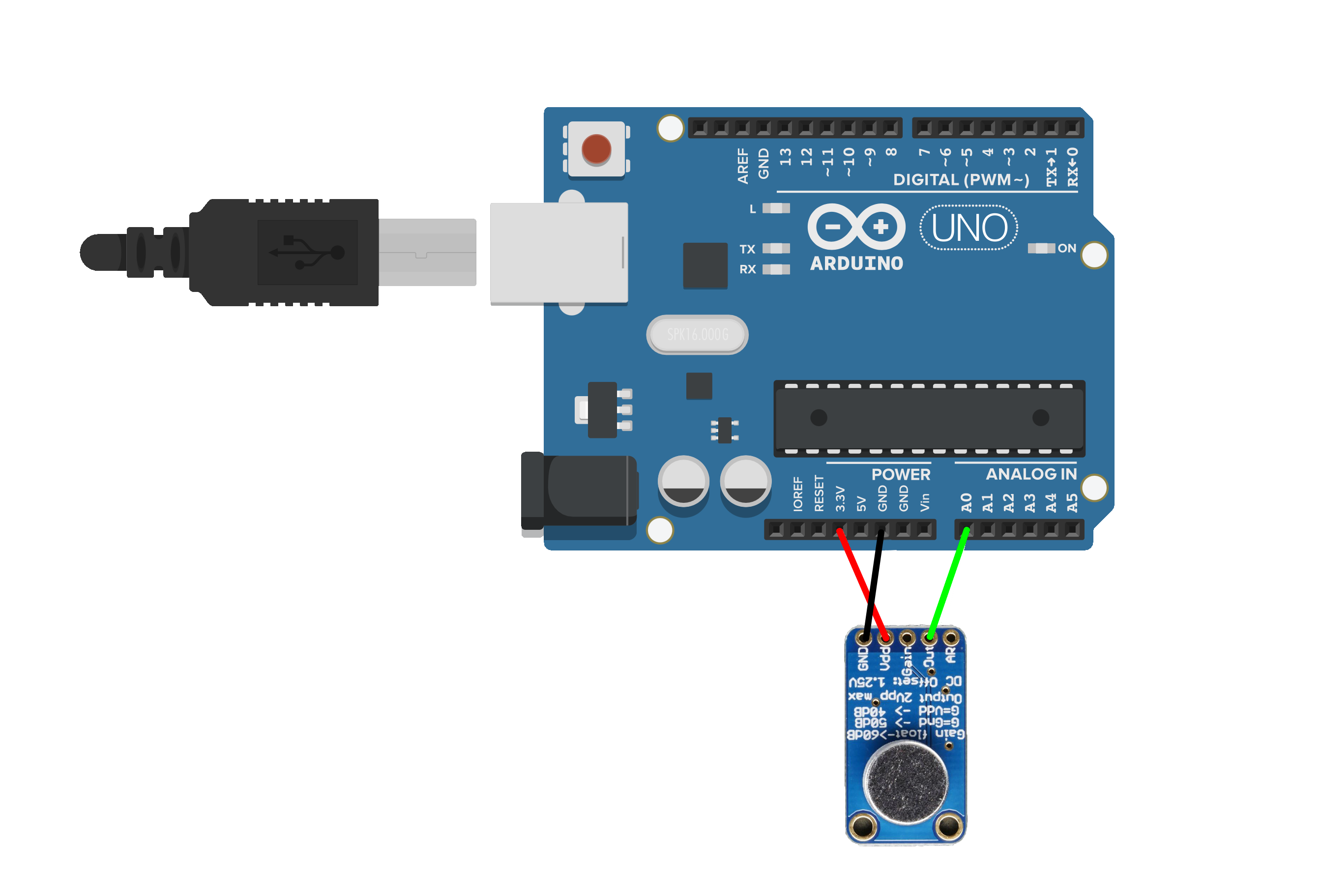
Retrieving Data
This code allows instructs the mic to detect and prints out values corresponding to the sound's varying volume.
int MicPin = A0;
int MicVolume = 0; // Define a variable MicVolume and initialize it to 0
void setup() {
Serial.begin(115200); // Initialize serial communication
}
void loop() {
MicVolume = analogRead(MicPin);
Serial.println(MicVolume);
}You can check that your circuit is working by looking at the Serial Plotter; In the menu bar go to Tools > Serial Plotter or press Command + Shift + L on your keyboard. Make sure this is set to 115200 baud.
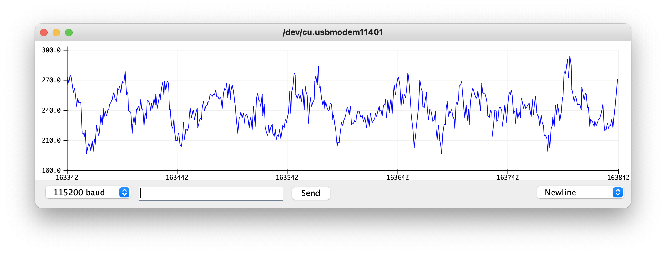
To utilise this data, you can temporarily slow down the data coming in from the mic and look to the Serial Monitor this time, to set up your own threshold, e.g. :
void loop() {
MicVolume = analogRead(MicPin);
if (MicVolume > 400) { // If the volume is above this threshold a warning comes up in the Serial Monitor
Serial.println("Loud noise");
delay(500);
} else {
Serial.println(MicVolume);
}
}Using the serial monitor and serial logger
What is serial communication?
Serial communication is a type of communication between two devices, normally between a computer and a microcontroller (such as an Arduino), between computers, or between Arduinos.
Serial communication can be over physical cables between two Arduinos, or via an XBee wireless shield, USB or Bluetooth serial emulators. However at it's most basic serial communication is a sequence of binary digits (0s and 1s) that convey information.
Serial monitor
The serial monitor on the Arduino is able to display messages the Arduino board sends via USB serial (note that Arduino Leonardo and some other boards based around the 32u4 chip have a seperate USB serial and hardware serial, and you cannot directly monitor the hardware serial [Serial1] output using this method).
You can also send basic messages from the serial monitor screen back to the Arduino board.

Above is a screenshot of the serial monitor, the first text field is where you can type text and press the send button to transmit to the Arduino. The main window below is where ASCII text will be displayed which the Arduino is transmitting.
In the middle at the bottom you can specify what character should be sent after each message you send, it's common to send a newline character to indicate each distinct message.
There is also an option "9600 baud" this is the communication speed. One of the fundamental parts of serial communication is establishing a common communication speed in bits (binary digits) per second, 9600 baud, is 9,600 bits per second. This drop down allows you to modify this setting, the default is 9600.
Serial plotter
The serial plotter is a way to visually graph the data being received, a common way to transmit multiple values is in a format called CSV (comma-seperated values) this is because when transmitting numbers you need to be able to distinguish between each number, if I transmitted the number 100 and the number 50 without a seperator they would look like this: 10050 and it would be impossible to decypher where one numbers starts and the next begins, instead we use a comma to seperate each value, thus the number becomes 100,50 and now we can easily see each value.
Also because we print a newline character (using println) after each loop we can see when each frame of data ends, thus allowing us to presume the numbers between the newline and the comma must be the first number.
Some Arduino boards transmit data much faster than others, in the case of the Arduino Leonardo it is perfectly possible to overload the computer with too much information and crash the Arduino application, so by adding a 1/20th second (50ms) delay we can slow the rate to a more than acceptable level.
This code example outputs the value of all 6 analog input pins on the Arduino:
void setup() {
Serial.begin( 9600 );
}
void loop() {
Serial.print( analogRead( A0 ) );
Serial.print( "," );
Serial.print( analogRead( A1 ) );
Serial.print( "," );
Serial.print( analogRead( A2 ) );
Serial.print( "," );
Serial.print( analogRead( A3 ) );
Serial.print( "," );
Serial.print( analogRead( A4 ) );
Serial.print( "," );
Serial.print( analogRead( A5 ) );
Serial.println();
delay( 50 );
}
The serial plotter has in built support detecting CSV data and displaying it as a graph over time. The biggest drawback is that it scales the graph to the current minimum and maximum, which can cause the graph to jump scale.
A simple fix to this problem is to include two fake piece of data which are the minimum and maximum of your data range, by modifying the Serial.println() to:
Serial.println( ",0,1023" );
In this case the minimum is 0, and because analogRead's on most Arduinos are only 10-bit this means the maximum number would be 1023.
void setup() {
Serial.begin( 9600 );
}
void loop() {
Serial.print( analogRead( A0 ) );
Serial.print( "," );
Serial.print( analogRead( A1 ) );
Serial.print( "," );
Serial.print( analogRead( A2 ) );
Serial.print( "," );
Serial.print( analogRead( A3 ) );
Serial.print( "," );
Serial.print( analogRead( A4 ) );
Serial.print( "," );
Serial.print( analogRead( A5 ) );
Serial.println( ",0,1023" );
delay( 50 );
}
Using Smartphont to Read NFC tag
What is NFC?
NFC (Near Field Communication) is a short-range wireless technology that allows two electronic devices to communicate when they are within a few centimeters of each other. It’s most commonly used in contactless payments, digital keycards, smart tags, and tap-to-share features. NFC works by using magnetic field induction and doesn’t require pairing like Bluetooth — just a simple tap is enough to exchange data.
In this tutorial, we are using an iPhone to tap on the NTAG203 to open up a link. This tutorial is more intensive and will be more useful if you have other interactive components in your project involving Arduino.
If you only want a simple read and write function, we have another tutorial which shows you how to read and write an NFC tag using the app NFC tools.
Wiring and Library
We will be using DFRobot PN532 module, please refer to this tutorial.
We will be using Adafruit_PN532 library, we have a tutorial on how to install a library here.
Types of Tag
In this tutorial, we are using NTAG203, NTAG215 or NTAG216 should work fine as well. You cannot use MIFARE Classic tag or card.
Code for Writing Data
#include <Wire.h>
#include <Adafruit_PN532.h>
#define SDA_PIN A4
#define SCL_PIN A5
Adafruit_PN532 nfc(SDA_PIN, SCL_PIN);
//your url
const char *url = "youtube.com"; // Keep short due to 144 byte limit & omit the "https://" part
uint8_t urlPrefix = 0x01; // 0x01 = http://www.
void setup(void) {
Serial.begin(115200);
Serial.println("Starting NFC writer with Adafruit PN532");
nfc.begin();
uint32_t versiondata = nfc.getFirmwareVersion();
if (!versiondata) {
Serial.println("Didn't find PN532 board");
while (1);
}
nfc.SAMConfig(); // configure board to read RFID
Serial.println("Waiting for an NFC tag...");
}
void loop(void) {
uint8_t uid[] = { 0 };
uint8_t uidLength;
if (nfc.readPassiveTargetID(PN532_MIFARE_ISO14443A, uid, &uidLength)) {
Serial.println("Tag detected!");
// Build NDEF URI record
uint8_t urlLength = strlen(url);
uint8_t payloadLength = 1 + urlLength; // Prefix + URL
uint8_t ndef[] = {
0xD1, // MB, ME, SR, TNF=0x01 (well-known)
0x01, // Type Length = 1
payloadLength, // Payload Length
0x55, // Type = 'U'
urlPrefix // URL Prefix
};
uint8_t messageLength = sizeof(ndef) + urlLength;
uint8_t totalLength = messageLength + 3; // TLV: 0x03 len + msg + 0xFE
uint8_t full[totalLength];
full[0] = 0x03; // NDEF Message TLV tag
full[1] = messageLength; // Length of NDEF message
memcpy(&full[2], ndef, sizeof(ndef));
memcpy(&full[2 + sizeof(ndef)], url, urlLength);
full[totalLength - 1] = 0xFE; // Terminator TLV
// Write to tag starting at page 4
int page = 4;
for (int i = 0; i < totalLength; i += 4) {
uint8_t buffer[4] = {0x00, 0x00, 0x00, 0x00};
for (int j = 0; j < 4 && (i + j) < totalLength; j++) {
buffer[j] = full[i + j];
}
if (!nfc.ntag2xx_WritePage(page, buffer)) {
Serial.print("Failed writing to page ");
Serial.println(page);
return;
}
page++;
}
Serial.println("Wrote NDEF URL to NTAG203 successfully!");
delay(5000); // prevent immediate re-trigger
}
}
Using NFC Tools to Read/Write NFC tag
What is NFC Tools?
NFC Tools is an app which allows you to read, write and program tasks on your NFC tags and other compatible NFC chips.
Simple and intuitive, NFC Tools can record standard information on your NFC tags which will be compatible with any NFC device. For instance, you can easily store your contact details, an URL, a phone number, your social profile or even a location.

We have another tutorial which shows you how to read and write an NFC tag using the Arduino, which is more intensive and useful if you have other interactive components in your project involving Arduino..
Types of Tag
In this tutorial, we are using NTAG203, NTAG215 or NTAG216 should work fine as well. You cannot use MIFARE Classic tag or card.
Steps
- Download the app, it is available for both iPhone and Android.
- Choose
Write.
- Add a record.

-
URL/URIto open a link, there are other functions that you can explore.
- Put in your link.

- Hold the tag near your phone and press
Write.
- All done! Whoever tap on the tag, their phones will open the link.
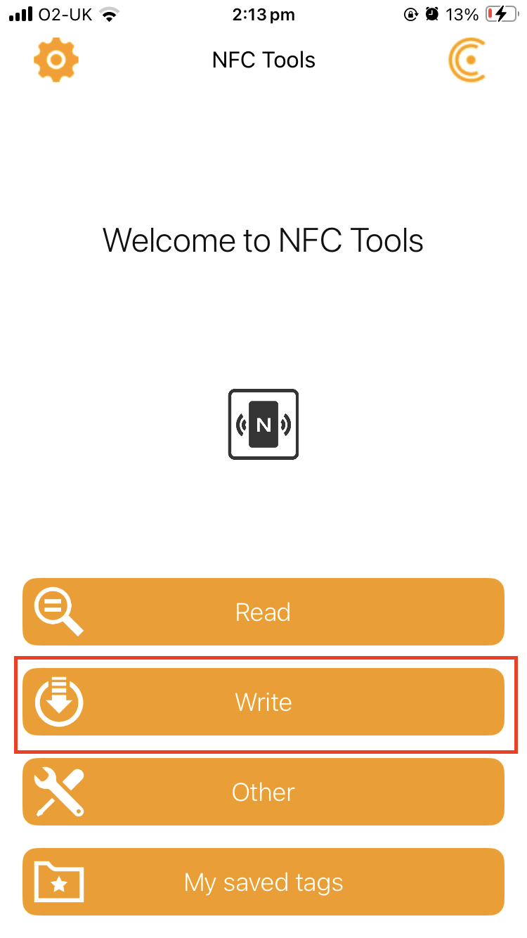

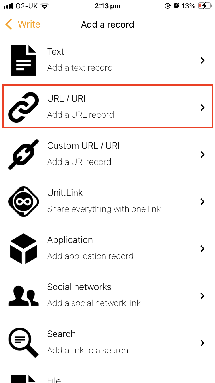


Something More
You can pair the NFC tag with iOS all Shortcuts to do some simple automated actions.