Workshop: Beginner Physical Computing
- Introduction
- Understanding Arduino hardware
- Understanding Arduino software
- Using built-in example code and Reading the hookup diagram
- Combining codes & circuits
Introduction
This chapter is designed for complete beginners who are new to working with physical computing and Arduino. If you haven’t had a chance to attend the physical workshop at the Creative Technology Lab, don’t worry—this guide will walk you through the basics.
If you visit the Creative Technology Lab (Room WG14), you can borrow a workshop kit to use in the lab and follow along with the instructions below.
In this workshop, you will learn:
- Understanding Arduino hardware
- Understanding Arduino software
- Using built-in example code and Reading the hookup diagram
- Installing libraries
- Using Neopixel
- Using Ultrasonic distance sensor
- Combining codes & circuits
Understanding Arduino hardware
In the kit, you will find an Arduino and two USB cables (USBC or USBA, pick the one that fits your computer).
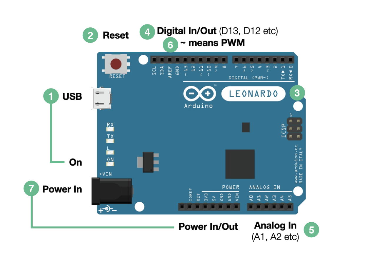
1. Micro USB Port
Connect the Arduino with your computer using the USB cable, you will see the yellowish light turned on.
2. RESET Button
It is not the factory reset button than you may find in other gadgets, but more like a restart button. If your Arduino freezes, lags or does anything weird, you can press the button.
3. Arduino Model
The white label indicates the model we are using. In the kit, you will find a LEONARDO, and we will need this piece of information later.
4. Digital Input/ Output
Digital means two states only, yes or no. Input can be something like a button, pressed / not pressed. Output can be something like an LED light, light on or light off.
5. Analog Input
Analog will give you something more than yes or no. For example, analog input can be something like a temperature sensor, instead of just hot and cold, it will give you degress degree celsius, a range of values.
6. PWM pins
You can see the symbol ~ next to some digital pins, those are PWM pins. For now, you can see them as analog output pins. For example, if you want to create a breathing light effect with the LED light, you will need to use one of those PWM pins.
7. Power Input/ Output
At the moment, we are using our computers as the power source via the micro USB port. When you finalise the setup, you won't need your computer with the setup, you can switch the power source to a power adapter, phone charger, batteries etc.
All other components that will be added to the circuit will need a power supply too, so we will make the Arduino as the "second battery" and use the power output pins to power them all.
Go to the next part, Understanding Arduino software.
Understanding Arduino software
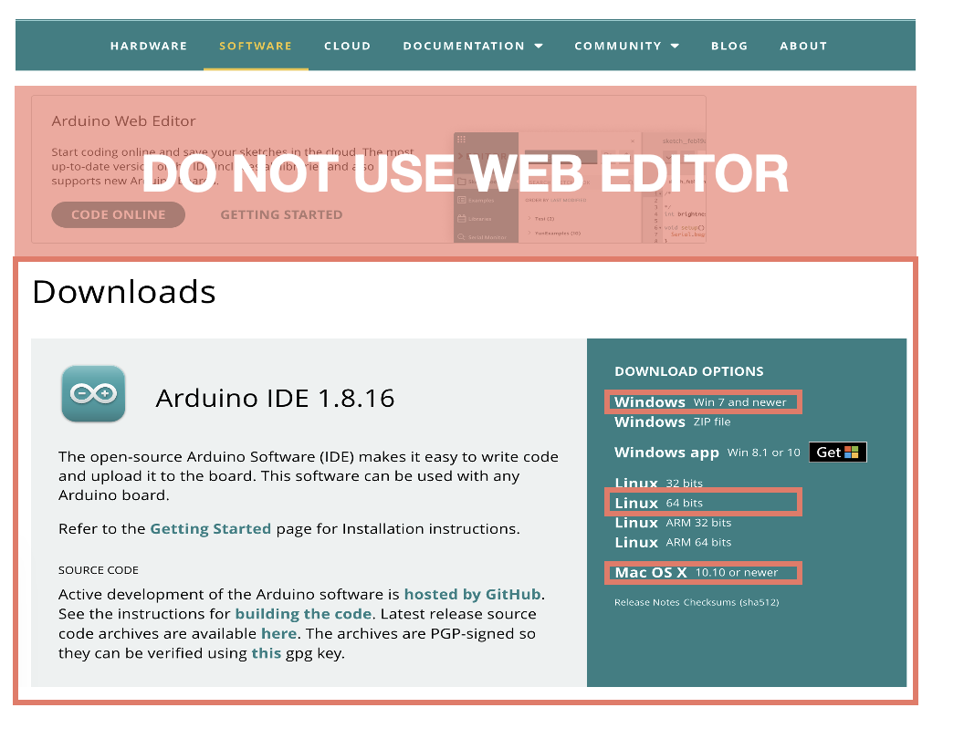
1. Download the software
Go the the official site and dowaload the 1.8.XX version! The latest version, 2.3.X, is not currently supported by all third-party development, so you may encounter unexpected errors. For the time being, please stick with the older version.
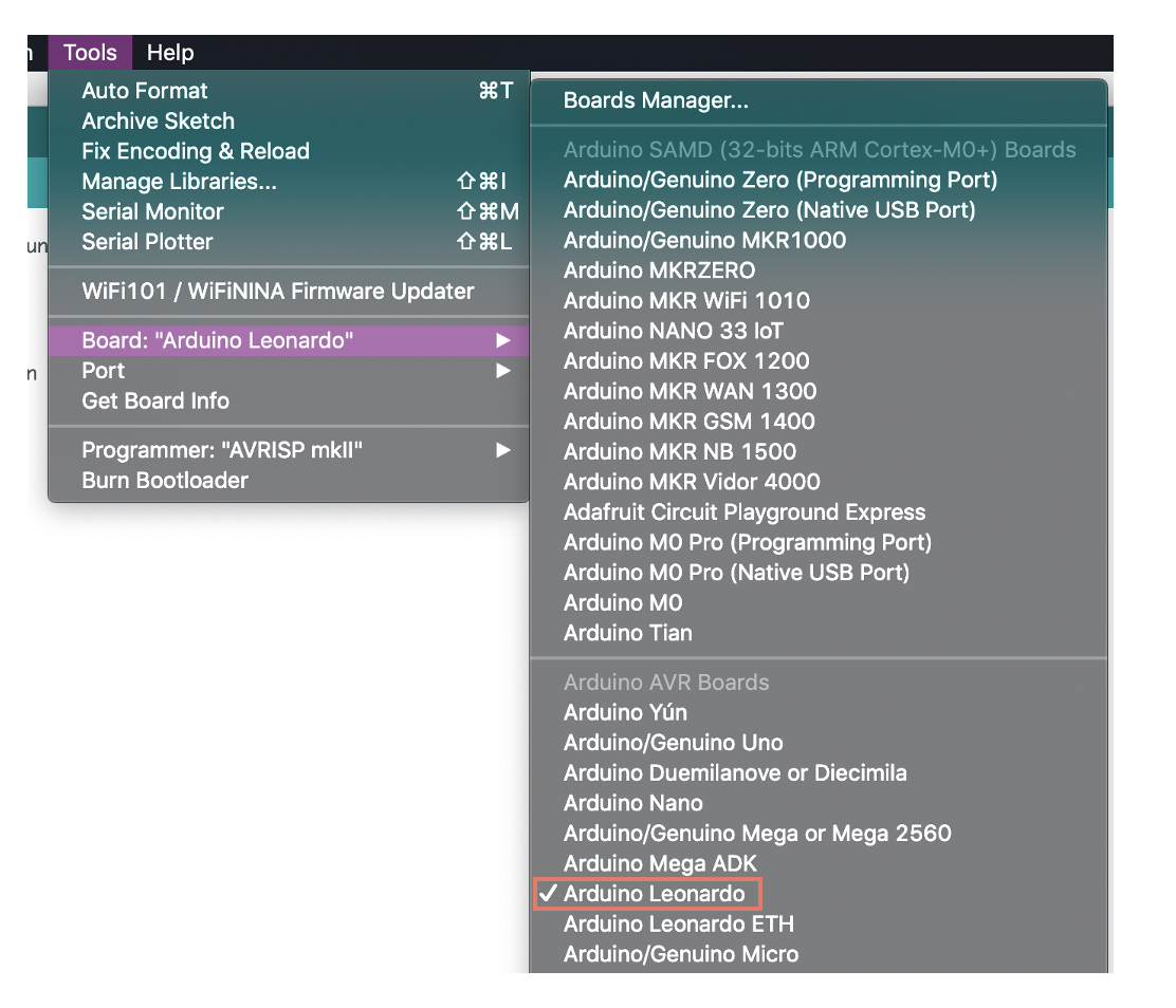
2. Select Arduino Board
We need to tell Arduino IDE which model we are using, so it can configure accordingly.
Tools -> Board -> Arduino Leonardo
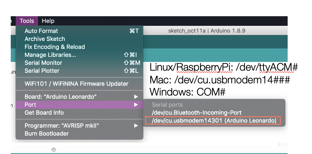
3. Select Serial Port
We are now connecting the Arduino and computer via the USB cable. All USB ports may be the same to use, but they are all unique to the computer, so we have to tell Arduino IDE which one exactly we are using. The one you are using, you will see XXXXXXXXXXX (Arduino Leonardo). In this screencap, you see 14301, yours may not be the same, if you are using a Windows PC, you will see COM# (Arduino Leonardo)
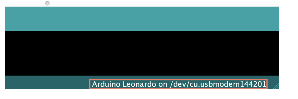
4. Double Check
Now at the bottom of the software, you will see you are using Arduino Leonardo at this specific port.
5. Upload Button
We are not going into the details of each button, but the Arrow button is the upload button to upload the code to the Arduino board. In the later part of this chapter, please use this button to upload the code to the Arduino.

Go to the next part, Using built-in example code and Reading the hookup diagram
Using built-in example code and Reading the hookup diagram
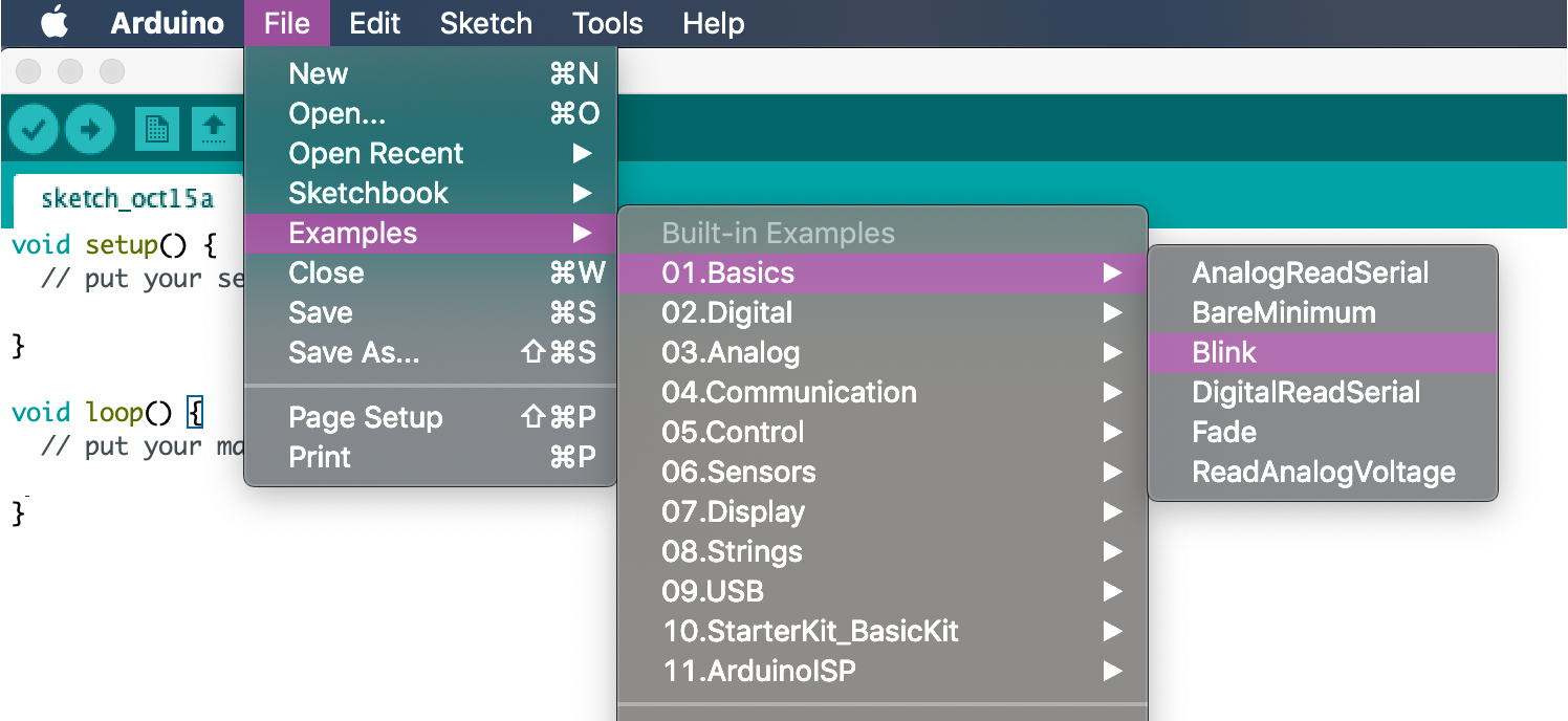
1. Upload example code
Open a built-in example, Blink, and upload the code.
2. Blinking Orange LED
The orange LED labelled as L should be blinking now.

3. Understanding the Code
- First, you will see a lot of light grey coloured text, those are comments, not code. You will find a lot of information from these comments to help you understand the code.
- Arduino is using the langauge C++.
- if you add
//in front of anything, the rest of the line will become a comment as well. - Next, you will see two main parts,
void setup() {}andvoid loop() {}, this is the main structure of Arduino code. - In the
setup(), usually we establish what component we are going to control and what are they. -
pinMode(LED_BUILTIN, OUTPUT);we are using the built-in on-board tiny LED and it is an output as it is a light. - In
loop(), as the name suggested, it will loop forever. -
digitalWrite(LED_BUILTIN, HIGH);means we are writing a command to this component, LED_BUILTIN, digitally, which means on or off only. And we choose HIGH, turn it on. -
delay(1000);delay means whatever you are doing, freeze there for this amount of time, 1000 is 1000 milliseconds, which is 1 second. Therefore, the light stays on for 1 second. -
digitalWrite(LED_BUILTIN, LOW);Again, writing a command digitally, but this time LOW, turn it off.delay(1000);stays off for a second. - Therefore, our orange light is blinking every 1 second.
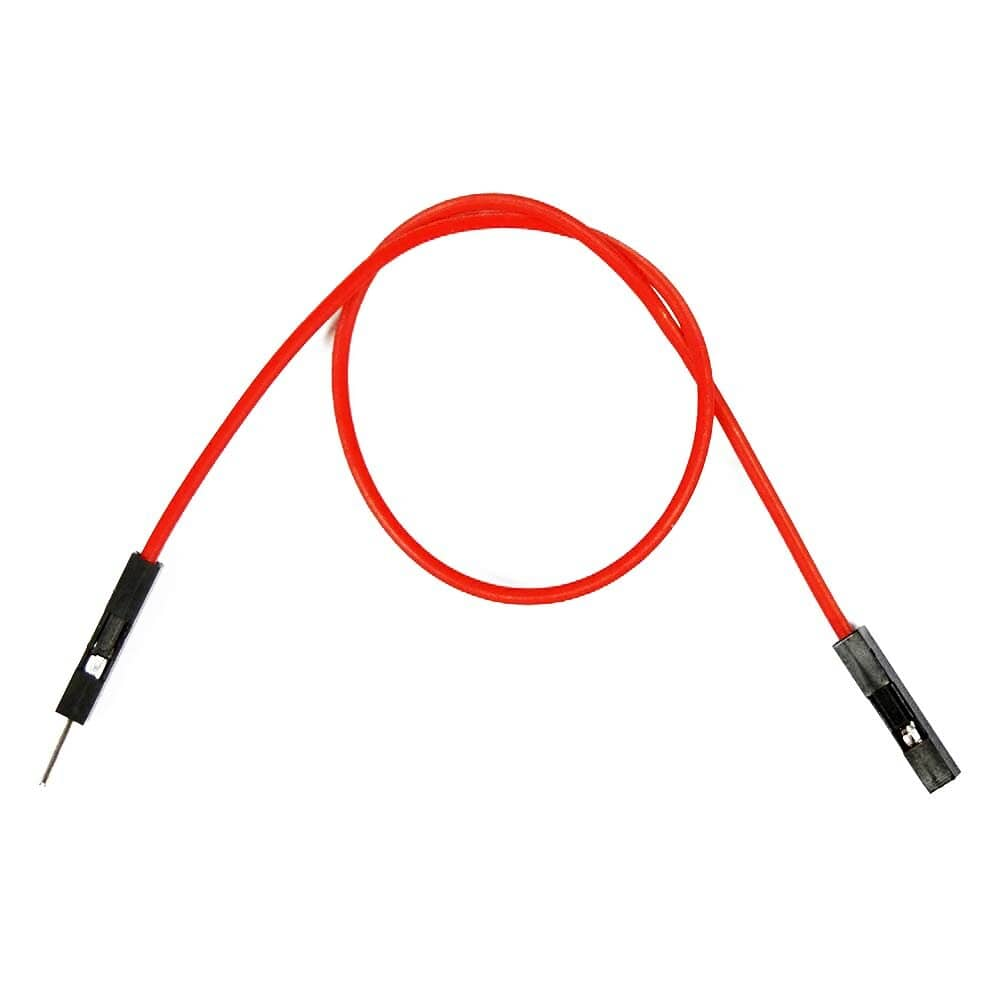
4. Getting ready for the circuit
We will use jumper wire with one pin end and one socket end (male to female) to make the connections.
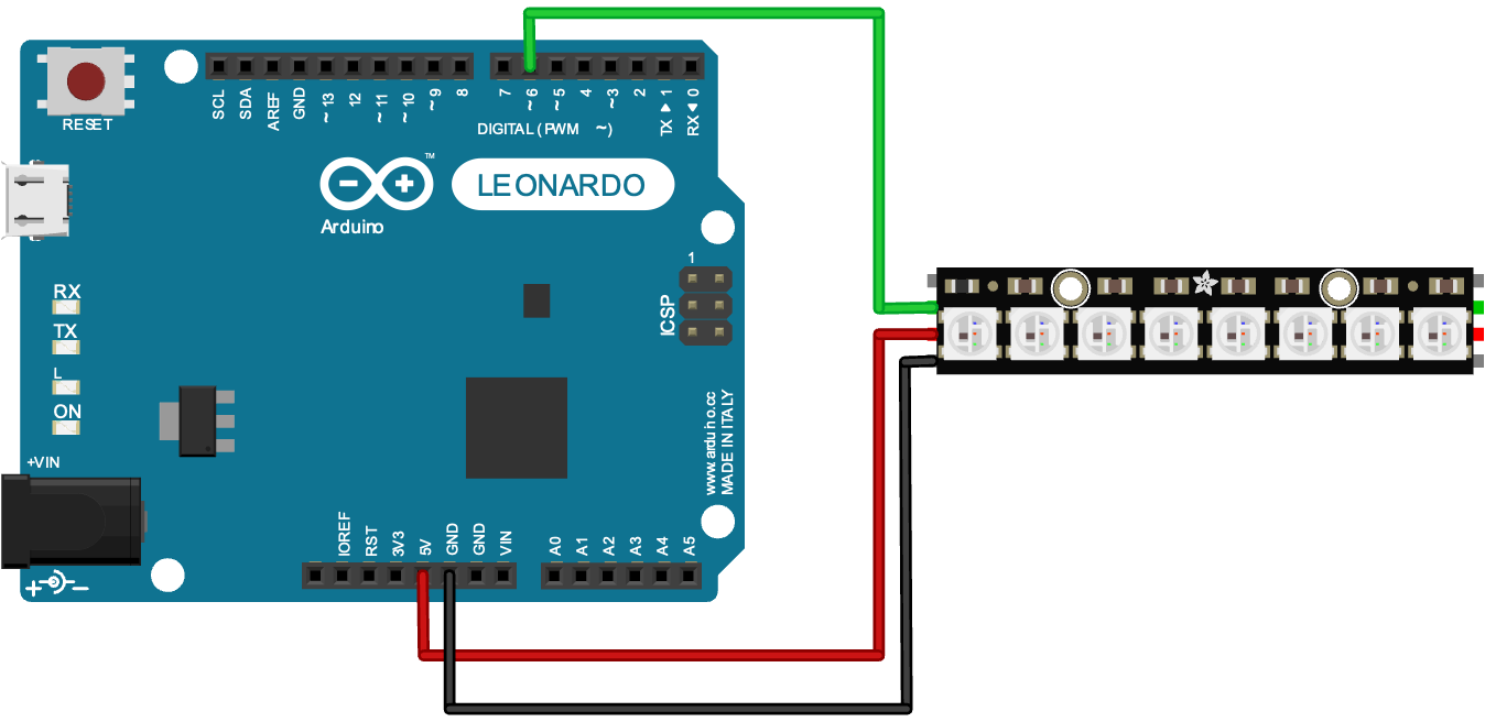
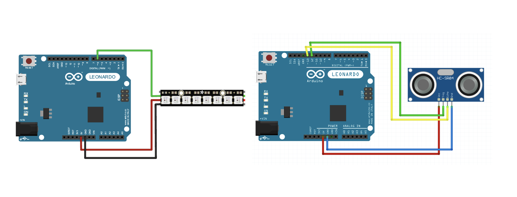
5. Reading the hookup diagram
Whenever you see a diagram like this, it's very tempting to count first goes there, second goes there, Don't do this! Instead, read the labels next to each pin and make the connections based on the pin labels.
For example, now you should have a neopixel stick with you, read the pin label on the back of the stick and the labels on the Arduino board, and try to match the labels.
- neopixel: 5VDC -> Arduino: 5V
- neopixel: GND -> Arduino: GND
- neopixel: DIN -> Arduino: ~6
Next, you will follow some tutorials about installing libraries, finishing learning how to use Neopixel and using the Ultrasonic Distance sensor. After finishing all the tutorials, please come back to the final bit.
Combining codes & circuits
1. Combining the Code
Arduino can only accept one code at one time. If we want it to do multiple things at the same time, we have to combine everything into one single code.
The below demonstrate how to merge the Blink code and the distance sensor simple code from the Library HCSR04.
-
Only one
void setup()andvoid loop(), that means we have to copy everything from 1setupto anothersetup, from 1loopto anotherloop.
void setup () {
Serial.begin(9600); // We initialize serial connection so that we could print values from sensor.
pinMode(LED_BUILTIN, OUTPUT);
}
-
Variables are very useful for storing data and making our code tidy and accessible. For example, in
Serial.println(distanceSensor.measureDistanceCm());,distanceSensor.measureDistanceCm()is the distance value, and if we want to use the data, we will need to retype this long string of text multiple times. To make things easier, we can create a variable, like thisfloat distance = distanceSensor.measureDistanceCm();, float indicate distance will be a number with decimal place. -
if(){ }else{ }The if statement is the most common way to make a simple interaction between two components. For example:
if(distance < 10){
digitalWrite(led, HIGH);
delay(100);
}else{
digitalWrite(led, LOW);
delay(100);
}
This is the full code, the orange light will turn on when something is near and off when not.
#include <HCSR04.h>
UltraSonicDistanceSensor distanceSensor(13, 12); // Initialize sensor that uses digital pins 13 and 12.
void setup () {
Serial.begin(9600); // We initialize serial connection so that we could print values from sensor.
pinMode(LED_BUILTIN, OUTPUT);
}
void loop () {
// Every 500 miliseconds, do a measurement using the sensor and print the distance in centimeters.
float distance = distanceSensor.measureDistanceCm();
Serial.println(distance);
if(distance < 10 && distance > 0){
digitalWrite(led, HIGH);
delay(100);
}else{
digitalWrite(led, LOW);
delay(100);
}
}
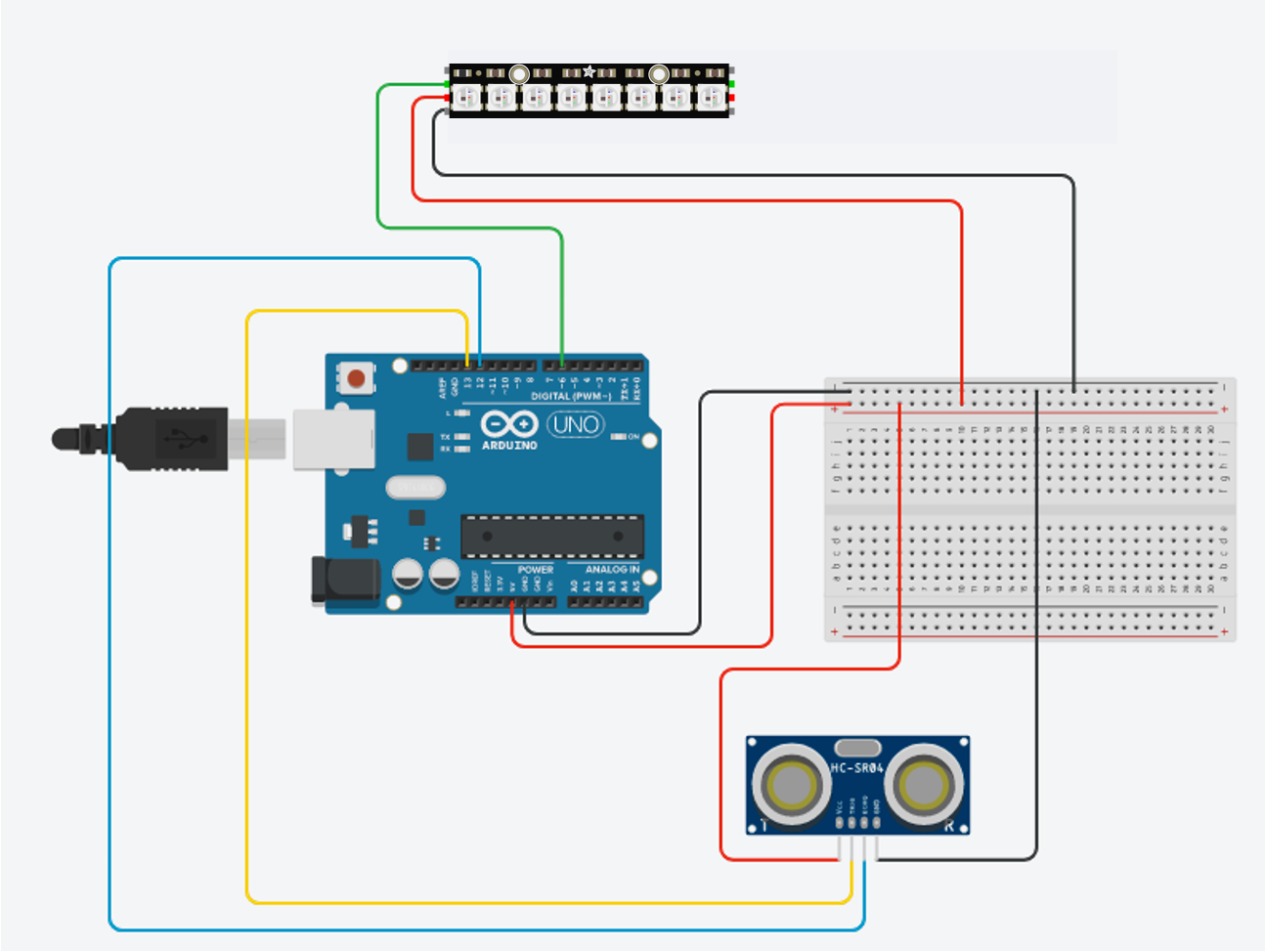
2. Combining the Circuit
And of course, we will need to merge the circuit as well. But you may notice there is only one 5V and both components need it.
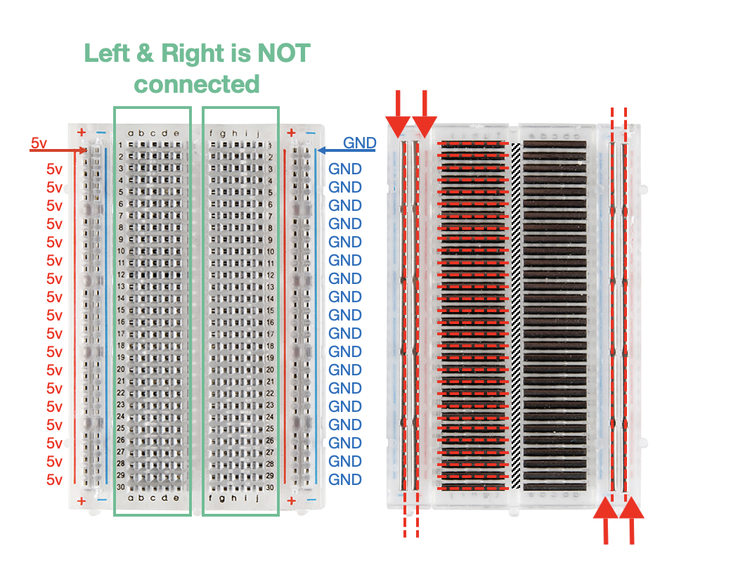
3. Using the Breadboard
A breadboard is the extension lead for electronics. The two columns at each side are connected vertically. The inner rows are connected horizontally. You can see a tiny gap right down the middle of the breadboard, which acts like a river, separating the left side and the right side.
4. Building the Circuit
Extending the 5V and GND to the Breadboard:
- 5v –> (+) column
- GND –> (-) column
Neopixels:
- 5VDC -> (+) column
- GND -> (-) column
- DIN -> 6
Distance Sensor
- VCC -> (+) column
- GND -> (-) column
- TRIG -> 13
- ECHO -> 12
4. Uploading the code
We have prepared a code for this setup. The main goal of this workshop is understanding the logic of the code. So, if you somewhat understand what is going on in the below code, Congrats!
#include <HCSR04.h>
UltraSonicDistanceSensor distanceSensor(13, 12);
#include <Adafruit_NeoPixel.h>
#ifdef __AVR__
#include <avr/power.h> // Required for 16 MHz Adafruit Trinket
#endif
// Which pin on the Arduino is connected to the NeoPixels?
// On a Trinket or Gemma we suggest changing this to 1:
#define LED_PIN 6
// How many NeoPixels are attached to the Arduino?
#define LED_COUNT 8
// Declare our NeoPixel strip object:
Adafruit_NeoPixel strip(LED_COUNT, LED_PIN, NEO_GRB + NEO_KHZ800);
// Argument 1 = Number of pixels in NeoPixel strip
// Argument 2 = Arduino pin number (most are valid)
// Argument 3 = Pixel type flags, add together as needed:
// NEO_KHZ800 800 KHz bitstream (most NeoPixel products w/WS2812 LEDs)
// NEO_KHZ400 400 KHz (classic 'v1' (not v2) FLORA pixels, WS2811 drivers)
// NEO_GRB Pixels are wired for GRB bitstream (most NeoPixel products)
// NEO_RGB Pixels are wired for RGB bitstream (v1 FLORA pixels, not v2)
// NEO_RGBW Pixels are wired for RGBW bitstream (NeoPixel RGBW products)
void setup() {
Serial.begin(9600);
//pinMode(3, OUTPUT);
#if defined(__AVR_ATtiny85__) && (F_CPU == 16000000)
clock_prescale_set(clock_div_1);
#endif
// END of Trinket-specific code.
strip.begin(); // INITIALIZE NeoPixel strip object (REQUIRED)
strip.show(); // Turn OFF all pixels ASAP
strip.setBrightness(50);
}
void loop() {
float distance = distanceSensor.measureDistanceCm() ;
Serial.println(distance);
if (distance > 0){
if (distance>=10 && distance < 30 ){
//digitalWrite(3, LOW);
strip.clear();
int j = map(distance,10, 30, 0, strip.numPixels());
Serial.println(j);
for(long firstPixelHue = 0; firstPixelHue < 3072; firstPixelHue += 256) {
for(int i=0; i<=j; i++) { // For each pixel in strip...
int pixelHue = firstPixelHue + (i * 65536L / strip.numPixels());
strip.setPixelColor(i, strip.gamma32(strip.ColorHSV(pixelHue))); // Set pixel's color (in RAM)
}
strip.show();
delay(10);
}
}else if (distance >= 30){
for(long firstPixelHue = 0; firstPixelHue < 3072; firstPixelHue += 256) {
for (int i=0; i<strip.numPixels(); i++){
int pixelHue = firstPixelHue + (i * 65536L / strip.numPixels());
strip.setPixelColor(i, strip.gamma32(strip.ColorHSV(pixelHue))); // Set pixel's color (in RAM)
}
strip.show();
delay(1);
}
}else {
//digitalWrite(3, HIGH);
for (int i=0; i<strip.numPixels(); i++){
strip.clear();
strip.show();
}
}
}
}