How to use a rotary encoder
What is a rotary encoder?
A rotary encoder is an electromechanical device that converts the angular position or motion of a rotating shaft into electrical signals. These signals can be processed to determine rotational direction, position, and speed, making rotary encoders a key component in many types of control systems.
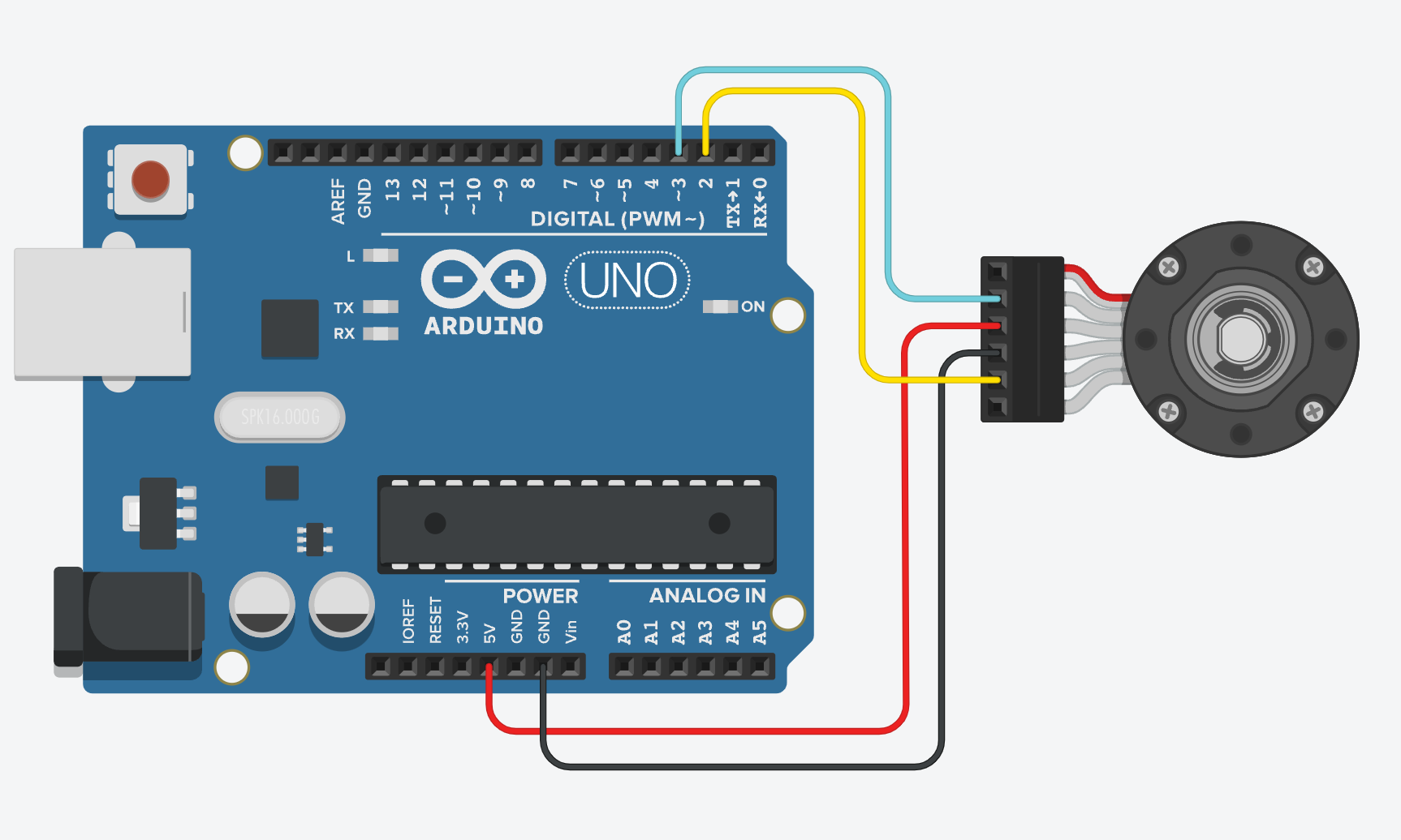
Wiring
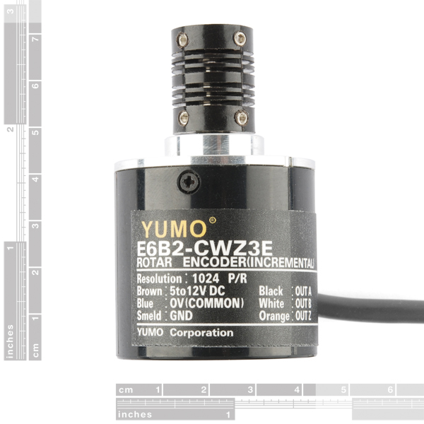 Different models of rotary encoders will have different colour codes. I am using an Incremental Rotary Encoder, YUMO E6B2-CWZ3E, the colours referred to below will only apply to this model.
There are four wires:
- Common (Blue) - GND
- Voltage (Brown) - 5V
- A switch (Black) - 2
- B switch ( White ) - 3
Getting started
The encoder produces pulses on the A and B channels as it rotates. These pulses are 90° out of phase (quadrature), which lets you detect both the amount of rotation and the direction. By reading these pulses with interrupts (which are triggered whenever the state of A or B changes), the Arduino can keep track of how far and in which direction the encoder has moved.
Key Types of Rotary Encoders
Incremental Rotary Encoder
- Outputs: Two signals (A and B channels) are generated as the shaft rotates, and these signals are in quadrature (90° out of phase).
- Working Principle: The encoder produces pulses as the shaft rotates. By counting these pulses, you can determine the angle or the distance travelled. The direction of rotation is determined by the relative timing of the A and B pulses.
- Applications: Motor control, robotics, CNC machines, etc.
- Endless rotation: They can rotate endlessly without resetting, but they only provide relative position information.
Here’s a simple visual explanation of how an incremental rotary encoder works:
         A Signal:   __|‾|__|‾|__|‾|__|‾|__|‾|
         B Signal:   _|‾|__|‾|__|‾|__|‾|__|‾|_
                    ← Rotate CW ←        ← Rotate CCW ←
When the shaft rotates, the A and B signals switch between high and low states. By detecting which signal changes first, you can determine the direction of rotation. Each pulse counts a step, which is related to the angular movement of the shaft.
Absolute Rotary Encoder
- Outputs: A unique signal (digital or analog) for each specific position of the shaft.
- Working Principle: Absolute encoders generate a unique code or position value for every possible shaft angle. This allows you to always know the exact position, even after power is cycled.
- Applications: Industrial automation, robotics, and anywhere precise positional feedback is needed.
- Single-turn vs. Multi-turn: Single-turn encoders measure the position within a single rotation, while multi-turn encoders also keep track of the number of rotations.
Basic Example
In this basic example, the encoder outputs the value as a positive or negative number from its starting position.
// Pin definitions
const int encoderPinA = 2;
const int encoderPinB = 3;

// Variables to store current and previous states of the encoder
volatile long encoderValue = 0;
volatile int lastEncoded = 0;

void setup() {
  // Setup the encoder pins as inputs
  pinMode(encoderPinA, INPUT);
  pinMode(encoderPinB, INPUT);

  // Enable pullup resistors on the encoder pins
  digitalWrite(encoderPinA, HIGH);
  digitalWrite(encoderPinB, HIGH);

  // Attach interrupt to the encoder pins
  attachInterrupt(digitalPinToInterrupt(encoderPinA), updateEncoder, CHANGE);
  attachInterrupt(digitalPinToInterrupt(encoderPinB), updateEncoder, CHANGE);

  Serial.begin(9600);
}

void loop() {
  // Print the encoder value (step count)
  Serial.print("Encoder Value: ");
  Serial.println(encoderValue);
  delay(100); // Adjust for your needs
}

void updateEncoder() {
  // Read the encoder pins
  int MSB = digitalRead(encoderPinA); // MSB = most significant bit
  int LSB = digitalRead(encoderPinB); // LSB = least significant bit

  int encoded = (MSB << 1) | LSB; // Combine A and B into a single value
  int sum = (lastEncoded << 2) | encoded; // Combine previous and current values

  // Determine the direction of rotation
  if (sum == 0b1101 || sum == 0b0100 || sum == 0b0010 || sum == 0b1011) {
    encoderValue++; // Clockwise
  } else if (sum == 0b1110 || sum == 0b0111 || sum == 0b0001 || sum == 0b1000) {
    encoderValue--; // Counter-clockwise
  }

  lastEncoded = encoded; // Store the current state for the next loop
}