Using a TCS34725 RGB Color Sensor
What is the TCS34725 RGB Color Sensor?
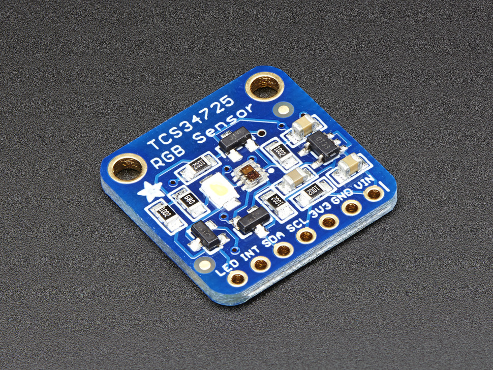
The TCS3472 sensor provides a digital return of red, green, blue (RGB), and clear light sensing values. An RGB Color sensor helps you accurately detect an object’s colour in your Arduino projects.
What is I2C?
The TCS34725 has an I2C interface (SDA and SCL) that connects to the Arduino Board. The IC also has an optional interrupt output pin which can be used to interrupt Arduino.
I2C stands for Inter-Integrated Circuit. It is a bus interface connection protocol incorporated into devices for serial communication. I2C Communication Protocol uses only 2 bi-directional open-drain lines for data communication called SDA and SCL. Both these lines are pulled high. Each data bit transferred on SDA line is synchronized by a high to the low pulse of each clock on the SCL line.
- Serial Data (SDA) – Transfer of data takes place through this pin.
- Serial Clock (SCL) – It carries the clock signal.
I2C on different Arduino boards
The two major models you can find in Creative Technology Lab are UNO and LEONARDO. Both have I2C function but have a different pinout. For UNO, the SDA pin is A4 and SCL pin is A5. For LEONARDO, the SDA pin is SDA(pin 20) and SCL pin is SCL(pin 21).
Not every Arduino model has I2C function and not all of them have the same pinout. Check the model before you hook it up with the TCS34725 sensor. Learn more
Library
Adafruit TCS34725 will be used for this tutorial. We have a tutorial on how to install a library here.
Wiring
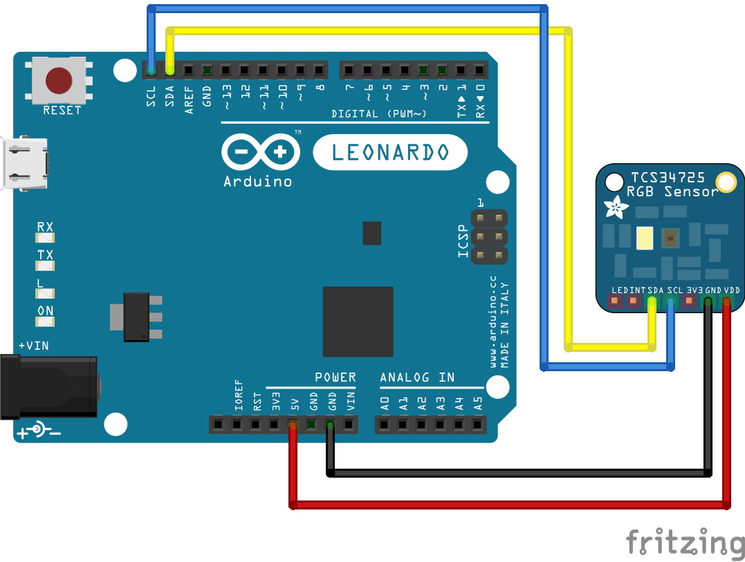
For LEONARDO, it's more like matching labels.
- GND - GND
- VIN - 5V
- SDA - SDA
- SCL - SCL
For UNO, A4 and A5 are the I2C pins rather than just a Analog Input pin.
- GND - GND
- VIN - 5V
- SDA - A4
- SCL - A5

Getting started
After installing the library and wiring the board, go ahead and use the examples in the File > Examples > Adafruit TCS34725 menu in Arduino, the tcs34725 example is particularly good as it's simple to check it's working.
Doing more
There is an example in the library for Arduino and Processing which can control the background colour using the colour sensor values.
- In the File > Examples > Adafruit TCS34725 >
colorviewin Arduino IDE, upload to Arduino. - In the File > Examples > Adafruit TCS34725 > examples_processing >
colorviewin Arduino IDE, copy and paste in a Processing sketch.
Serial Port
Before you run the code in Processing, we have to set up the serial port for the communication between Arduino and Processing. Go to line 15.
port = new Serial(this, "COM20", 9600);
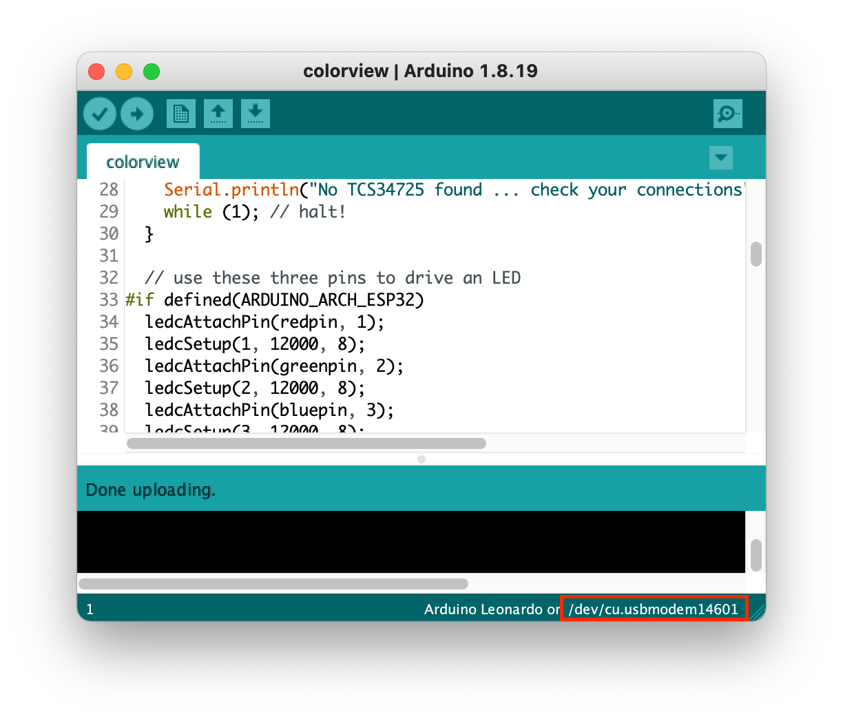
"COM20" is the name of the serial port, every USB port on everyone's computer is different. Replace "COM20" with your own port name. For me, my port name is "/dev/cu.usbmodem14601" so I changed the code like this.
port = new Serial(this, "/dev/cu.usbmodem14601", 9600);
You can find your port name at the bottom of your Arduino IDE or go to Tools > Port > ########(Arduino #####).