Projection Mapping
Intro to Projection Mapping
A general introduction to Projection Mapping
Intro
What is Projection Mapping?
Projection Mapping is a technique used to display content such as images or video onto irregularly shaped surfaces or objects. It is commonly used in advertising and stage design, but also by artists who wish to add depth or movement to static objects.
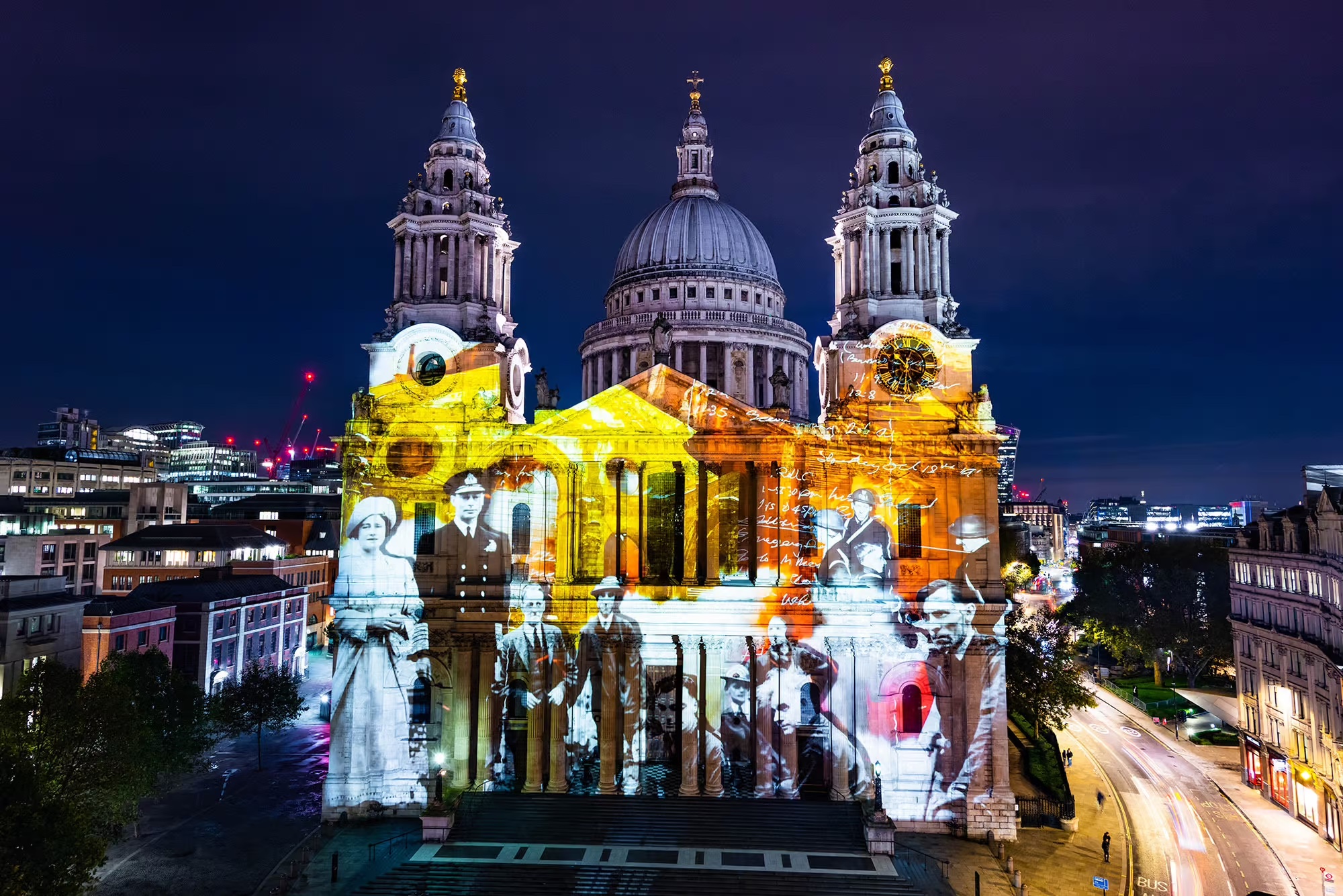
This technique was first used for Disney’s Haunted Mansion ride in 1969, where a video of five singing ghosts was projected onto physical busts, creating the illusion of movement. Since then, many creatives continue to incorporate projection mapping in their artistic practice, and the technique has expanded to incorporate more advanced methods, including 3D and immersive projections.
Software
![]()

A variety of projection mapping software and masking tools are available online; The Creative Technology Lab supports projects in Touchdesigner and Madmapper. While our "Intro to Projection Mapping" workshop introduces students to the technique in Touchdesigner, resources are available for both tools on this wiki.
Hardware
Selecting the right projector is crucial for projection mapping: Different projectors suit various environments and surfaces. LED or Laser projectors are ideal for dark rooms, offering intense colors and high resolution. For brighter rooms, Lamp projectors (3000 ANSI lumens or more) work best. It's important to handle lamp projectors carefully – mounting these upside down or from ceilings might damage the lamp inside.
Check out the variety of projectors available in college on ORB or speak to a technician to find out what might work best for your project.
Projection Mapping in Touchdesigner
Before we begin...
Make sure you have installed Touchdesigner, a tutorial on how to get the software started is available here. This tutorial will cover the basics to projection mapping content onto 3D surfaces in Touchdesigner, to learn more about this technique student can attend the 'Intro to Projection Mapping' workshop in the Creative Technology Lab.
Importing content in Touchdesigner
Double click anywhere on the interface to access the OP dialog, this is a "library" of all operators available in Touchdesigner. Operators are divided into families, in this tutorial we'll work with TOPs (Texture Operators).
Select the moviefilein TOP to import images or videos. You can change the default image to your own visuals by clicking on the ![]() button next to "File" in the parameters window.
button next to "File" in the parameters window.
Projection Mapping with kantanMapper
Now that we have uploaded our content we are ready to projection map it onto our object. Make sure to connect your projector to your laptop and that this is set up as an extended monitor: follow the steps provided here for Windows or here for iOS.
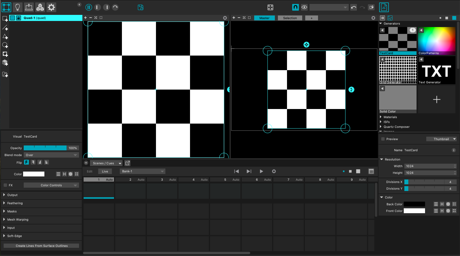
Open the Palette window by clicking on the ![]() button; The Palette is a collection of ready-made useful components (COMPs). In the Palette look for the group “Mapping”, all tools for projection mapping are found here. KantanMapper has been designer to easily mask your area of projection and warp your content onto it. Drag and drop it on your network.
button; The Palette is a collection of ready-made useful components (COMPs). In the Palette look for the group “Mapping”, all tools for projection mapping are found here. KantanMapper has been designer to easily mask your area of projection and warp your content onto it. Drag and drop it on your network.

In the parameters’ window on the right click on PULSE to open Kantan window, this will enable us to access this operator. At this point we have to inform Touchdesigner on where our projector is before masking the surface area we will project onto: To do that click on WINDOW OPTIONS, here use the “monitor” slider to specify the number that corresponds to your projector, this is usually 1. Change the “opening size” to FILL and hit UPDATE - this will make sure that your masking tool fills all of the screen area available. Scroll to the bottom of this window to “Open as Separate Window”, hit OPEN to view the masking tool.
You can now close this window and click on TOGGLE OUTPUT to finally start masking your area of projection. Select the freeform tool and click on the corners of your object to trace its perimeter. Make sure to close your shape before moving on. Other tools are also useful to transform your shape, read more about this here.
With the shape masking our area of projection read, we can now assign our moviefilein TOP as the "texture" of the shape, simply drag and drop this in the parameter and click the button near it to activate view the texture.
Find out more about kantanMapper in Touchdesigner: https://docs.derivative.ca/Palette:kantanMapper.
Projection Mapping in MadMapper
Why use MadMapper?
MadMapper is a powerful tool for projection mapping, especially when working at large scales — like projecting onto a building facade. Unlike TouchDesigner, MadMapper isn't free, but a 30-day demo version is available. The demo is great for testing but won't let you save projects.
Our lab holds a limited number of full licenses. These cannot be installed on personal devices, but you can borrow a machine with MadMapper pre-installed — just contact us.
If you're working on a large-scale projection (anything over 3 meters), MadMapper’s high-resolution output is ideal. Start by installing the DEMO version here: https://madmapper.com/madmapper/software.
Software Setup
Before launching MadMapper, make sure your displays are not mirrored:
-
macOS: Go to System Preferences > Displays, and uncheck "Mirror Displays".
-
Windows: Go to Display Settings, and choose "Extend these displays".
Import your content
MadMapper comes with a few built-in visuals, but to add your own:
-
Click the + icon on the right side to import images or videos.
-
You can also use Syphon or webcams as live inputs.
-
Drag your imported content into the empty area on the left to start working with it.
Adjusting and Transforming
MadMapper’s interface is split into two key areas:
-
Left side: Edit content—resize, crop, rotate, etc.
-
Right side: Map the content—adjust corners, apply masks, and shape your projection surface.
Project your output
-
Click the projector icon (top left).

-
Choose your projector from the list under Output Destination.
-
Adjust the Output Size if needed, or let it auto-adapt.
-
Enter Fullscreen mode via the Output > Fullscreen Mode menu or by pressing
Cmd + U(useCmd + Tto exit Fullscreen).
More resources are also available here: https://madmapper.com/madmapper/tutorials.
Interactive Projections
If you're interested in creating position-based interactive projections, the first step would be to map the space and track anyone/anything within it. This can be done in multiple ways, this tutorial will briefly introduce you to two different but related techniques:
Object detection and tracking in OpenCV
For most applications, your webcam and a bit of OpenCV script will be enough to analyse images and detect people or objects in real-time. If you haven't heard of OpenCV, it's a powerful Open source Computer Vision library and includes a variety of examples which can be implemented in Touchdesigner, using the Script TOP. Now it's important to know that we can't just copy and paste an OpenCV example into Touchdesigner, we will have to adapt various parameters to link our VideoDeviceIn TOP, import the correct libraries etc. A variety of resources are available online if you wish to learn more about OpenCV, an in-depth explanation of our following steps is also available here: https://www.youtube.com/watch?v=1Uw2PWTR_XM&t=529s.
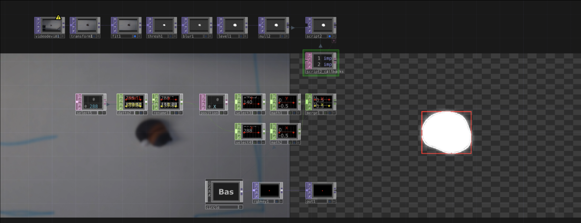
Begin by connecting your VideoDeviceIn TOP, to a Threshold Top and playing around with the Threshold value; Ideally you want to get completely transparent background and a white solid shape whenever an object is positioned within the monitored area. Experiment with Level TOP and Blur TOP to achieve a polished result.
After polishing your input, connect it to a new NullTOP, we'll rename this 'webcam'. To detect objects within a specific area, we will use OpenCV's Canny Edge Detection, a popular edge detection algorithm, together with the 'findContours()' function. Copy and paste the following script in your ScriptTOP, we will use this to draw a bounding box around the detected objects:
import cv2
import numpy as np
def onCook(scriptOp):
image = op('webcam').numpyArray(delayed=True)
gray = cv2.cvtColor(image, cv2.COLOR_RGB2GRAY)
gray_8bit = cv2.convertScaleAbs(gray)
edges = cv2.Canny(gray_8bit, 1, 5)
contours, hierarchy = cv2.findContours(edges, cv2.RETR_TREE, cv2.CHAIN_APPROX_SIMPLE)
dst = np.copy(image)
object_count = 1
for cnt in contours:
x, y, w, h = cv2.boundingRect(cnt)
cv2.drawContours(dst, [cnt], -1, (255, 255, 255), 1)
cv2.rectangle(dst, (x, y), (x + w, y + h), (255, 0, 0), 1)
scriptOp.copyNumpyArray(dst)
returnIn Script TOP, you should now get a new image with red boxes around the detected edges of your objects. Next we'll be retrieving the x and y position of our objects. Add a Table DAT to your project and let's rename this 'position'. Next we'll add a couple of expressions to print out the x and y coordinates of our bonding box, copy and paste the new code below:
import cv2
import numpy as np
def onCook(scriptOp):
image = op('null2').numpyArray(delayed=True)
gray = cv2.cvtColor(image, cv2.COLOR_RGB2GRAY)
gray_8bit = cv2.convertScaleAbs(gray)
edges = cv2.Canny(gray_8bit, 1, 5)
contours, hierarchy = cv2.findContours(edges, cv2.RETR_TREE, cv2.CHAIN_APPROX_SIMPLE)
dst = np.copy(image)
object_count = 1
# Link to Table DAT
table1 = op('position')
table1.clear()
# Add headers to the table
table1.appendRow(['X', 'Y'])
for cnt in contours:
x, y, w, h = cv2.boundingRect(cnt)
# Print contours position into table
table1.appendRow([x, y])
cv2.drawContours(dst, [cnt], -1, (255, 255, 255), 1)
cv2.rectangle(dst, (x, y), (x + w, y + h), (255, 0, 0), 1)
scriptOp.copyNumpyArray(dst)
returnYou should now numbers for both X and Y, each row represents a bounding box, you can filter rows out using the Select DAT. Convert the values from DAT using a DatTo CHOP and use these values to control the position of a circle or generate multiple circle as the base of your interaction.
Position tracking with LiDAR sensor
LiDAR technology can scan large areas by targeting a surface with a laser and measuring the time for the reflected light to return to the receiver; A Slamtec's RPLidar is a small scanner available for students to be used within the lab. The sensor requires a bit of prior set up to run, please allow some time for this process when planning the timeline of your project. Should you be using the desktop provided in the Multipurpose Booth, this step has already been done for you.
Windows
For Windows 10 and 11, begin by downloading Visual Studio, make sure you download the C++ app dev. Download the following GitHub repo: https://github.com/thepelkus-too/SlamtecLidarTDCPPCHOP. Unzip the folder and double click on the 'rplidar_sdk' folder, if empty download this repo (https://github.com/thepelkus-too/rplidar_sdk/tree/531cb0d1ef4bd95ccc3ed0a249787838836339f7) and paste it's content within your 'rplidar_sdk' folder. Now that your 'SlamtecLidarTDCPPCHOP-master' folder is ready, right-click on it and open in using VS Code. On the right hand side of the interface, look for 'CPlusPlusCHOPExample.sln' and double click on it. At this point VS Code will begin building your C++ solution, press OK if a pop-up window comes up. Check the terminal to find out if your built is completed. Please follow this tutorial for further instructions: https://youtu.be/fAvF2niosNA?si=8FYoHdmTat231lBA&t=626 - be aware that in the tutorial he calls it Visual Studio Code but it's Visual Studio you need!
Mac
Some Mac users will have it easier, but this plugin might not work on your laptop as it's only been tested out on my personal devices. Download the C++ plugin and read through the instructions to get started: https://github.com/creativetechnologylab/LiDAR-Sensor.
Should you have any issues feel free to contact me on Teams.
Following steps:
Download our pre-built rendering component: https://github.com/creativetechnologylab/LiDAR-Sensor/blob/main/LiDAR_Sensor.tox and drag it into a new Touchdesigner file. Once you're done with the set up, contact me via Teams to come test everything out with our sensor.
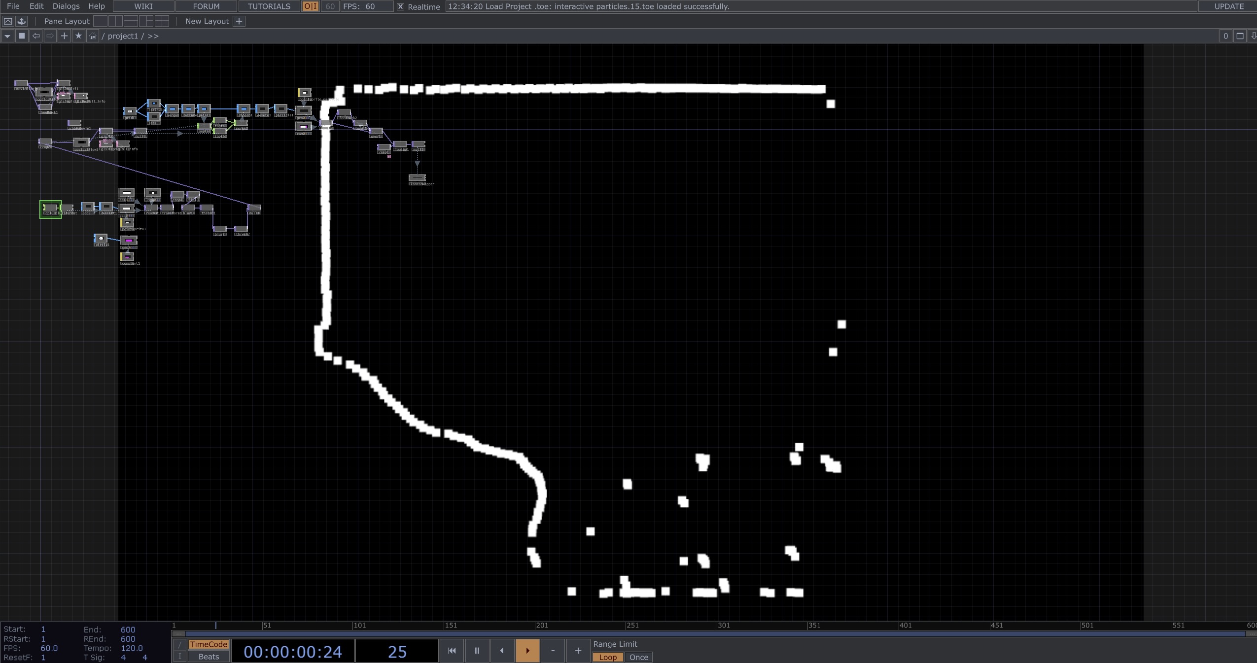
Using a Transform TOP, filter out any walls or areas you are not interested in monitoring. You can now use the same OpenCV code provided above to analyse your area and retrieve x and y coordinates for any detected object.