Raspberry Pi
What is Raspberry Pi and How to use a pi for beginner.
- What is a Raspberry Pi?
- What is a Raspberry Pi Pico?
- What are GPIO pins on Raspberry Pi?
- Raspberry Pi Image
- How to image a Raspberry Pi
- Raspberry Pi Image: Retropie for Reviving Vintage Games
- Raspberry Pi Image: Video Looper
- How to Configure a Raspberry Pi for the first time
- Tutorials
- How to make the Raspberry Pi display a web page fullscreen at power on
- How to power the Raspberry Pi Pico
- How to make two Raspberry Pi Pico communicate via Wifi
- How to control Raspberry Pi Pico via Wifi
- How to set the sound output in Raspberry Pi
- How to install Node.js on Raspberry Pi
- How to use Waveshare E-Paper Display with Raspberry Pi
- How to Display Animation on Waveshare E-Paper Display
- How to send files to Raspberry Pi using SSH
- How to use Raspberry Pi Camera Module 3
- How to do Basic Commands in Terminal
- Pi War 2024 Log
What is a Raspberry Pi?
What is Raspberry Pi?
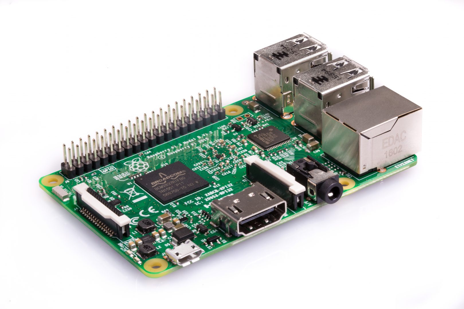
Raspberry Pi is a series of small single-board computers. The Raspberry Pi project originally leaned towards the promotion of teaching basic computer science in schools and developing countries. It is widely used in many areas because of its low cost, modularity, and open design.
The Raspberry Pi Foundation provides Raspberry Pi OS, a Debian-based Linux distribution for download. It promotes Python and Scratch as the main programming languages, with support for many other languages.
Things you need to know about your Pi
Raspberry Pi comes with a lot of different models and each of them has its own specs. To get started, you first need to know the model of your Pi and look at the specs.
Things you need to set up your Pi
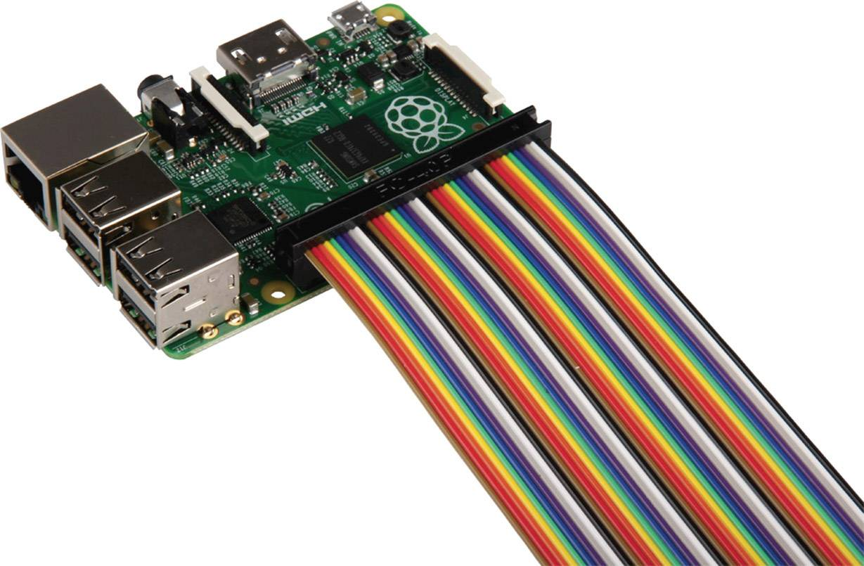
Raspberry Pi is a single-board computer. You can image it as the core of your computer but has no monitor, keyboard or mouse. It can run automated functions without all those things, but you still need them when you are setting up. All necessary parts are included in the CTH Raspberry Pi's kit.
1. Screen
You can use any screen, as long as it has a HDMI port and you have a power supply for the screen.
2. HDMI cable
Different models have different types of HDMI ports, you will need to find HDMI cable that matches your Pi.
- Pi 3: standard HDMI port x1
- Pi 4 & Pi 5: micro HDMI port x2
3. Mouse and with cable
You can also use the Bluetooth with a dongle type of mouse & keyboard.
4. Power Supply
Different models have different needs for Power supply. It is not necessary to buy the official power supply. However, you will need to find one that matches the needs of your pi, please refer to the official document.
- Raspberry Pi Zero 2 / Pi 3: 5V, 2.5A; Micro USB
- Raspberry Pi 4: 5V, 3A; USB-C
- Raspberry Pi 5: 5.1V, 5A; USB-C
5. SD card
The SD card acts as the hard drive of your Raspberry Pi. The higher storage means your pi can save more things on it. BUT, you have to be aware of the types and sizes of the SD card. There is a list for you to check the specific SD card's compatibility with Pi.
In general, I will suggest using one with at least 16GB.
6. Good to have
-
Ethernet Cable - In case you cannot log in to the WIFI, especially for non-open networks.
-
Fans - Overheating is a common problem for Pi, especially when running for hours.
-
Cameras - With cameras, you can do a lot of interesting projects with computer vision and images.
What is a Raspberry Pi Pico?
What is Raspberry Pi Pico?
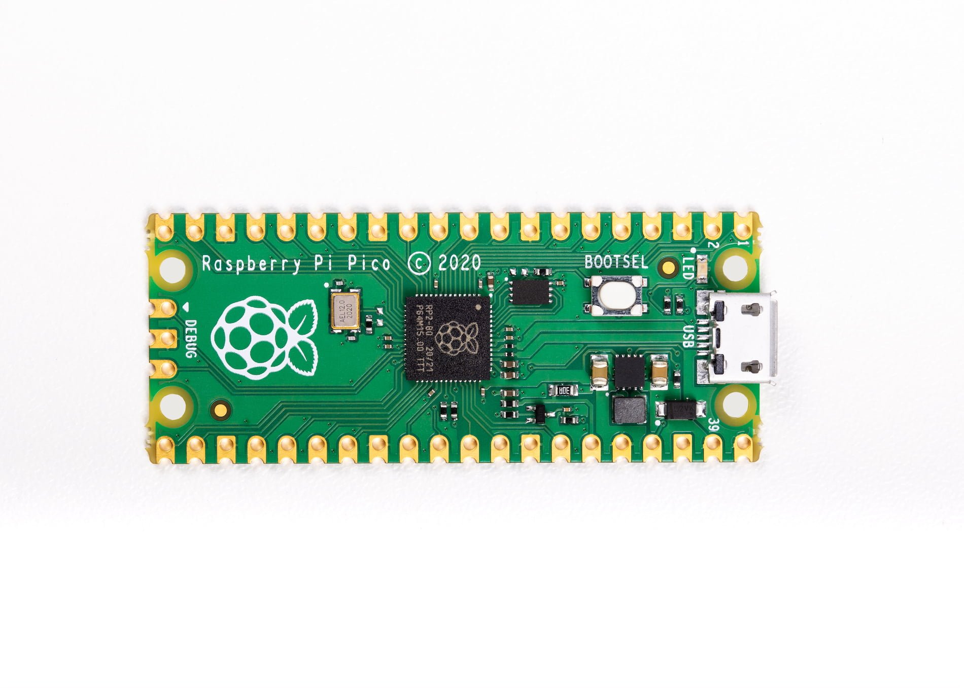
The Raspberry Pi Pico is a microcontroller board developed by the Raspberry Pi Foundation. It was announced in January 2021 and represents a departure from the traditional single-board computers (SBCs) that the Raspberry Pi Foundation is known for, such as the Raspberry Pi 3 or 4. Instead of being a full-fledged computer, the Raspberry Pi Pico is a microcontroller board designed for embedded projects and electronics prototyping. It is closer to an Arduino than a Raspberry Pi.
The Pico includes 26 programmable general-purpose input/output (GPIO) pins, which can be used for various digital and analogue tasks. The Pico can be programmed using MicroPython, a lightweight version of the Python programming language designed for microcontrollers. It also supports C and other programming languages. To know more about Pico.
At the moment, The Raspberry Pi Pico family currently consists of four boards; Raspberry Pi Pico, Pico H , Pico W, and Pico WH. Raspberry Pi Pico W and Pico WH have on-board single-band 2.4GHz wireless interfaces.
Set up your Pico
- Solder header pins onto the Pico, you can choose the types that you prefer.
- Choose a programming language for your Pico, in this tutorial, we will be using MicroPython.
- Download the correct MicroPython
.uf2file for your board. Raspberry Pi Pico or Raspberry Pi Pico W - Push and hold the BOOTSEL button.
- Plug your Pico into your computer with a USB cable.
- It will show up as an external drive called RPI-RP2.
- Copy the MicroPython
.uf2file onto the RPI-RP2. - Pico will reboot, then you are ready to go!
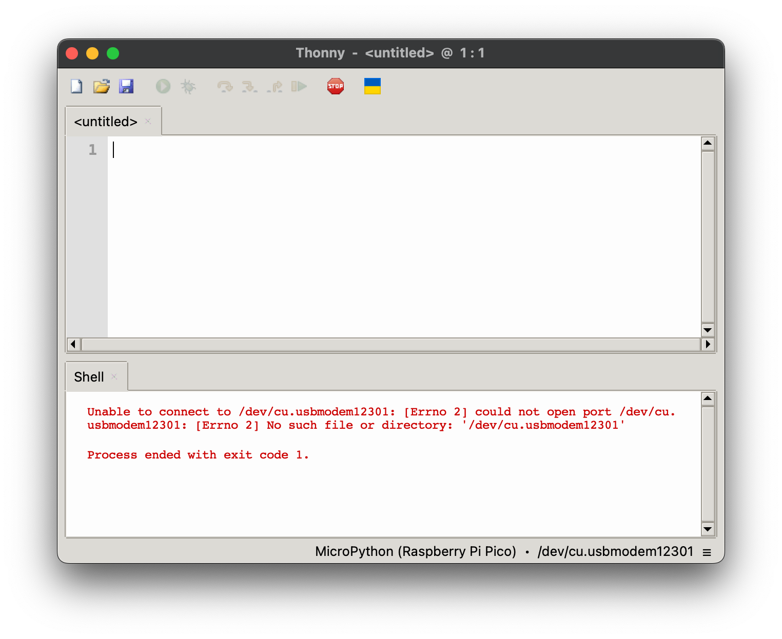
Download Thonny
Thonny is an integrated development environment (IDE) for Python programming. It is designed with beginners in mind and provides a simple and clean interface for writing and running Python code. Thonny includes features such as an interactive Python shell, a built-in package manager, and the ability to easily install and manage Python packages. Download here.
Get Started
This example code will blink the built-in LED every 0.5 seconds, using the machine library and the time module.
- Put in your code
from time import sleep
from machine import Pin
led = Pin("LED", Pin.OUT) #create LED object from pin13,Set Pin13 to output
while True:
led.value(1) #Set led turn on
time.sleep(0.5) #stay on for 0.5 seconds
led.value(0) #Set led turn off
time.sleep(0.5) #stay off for 0.5 seconds
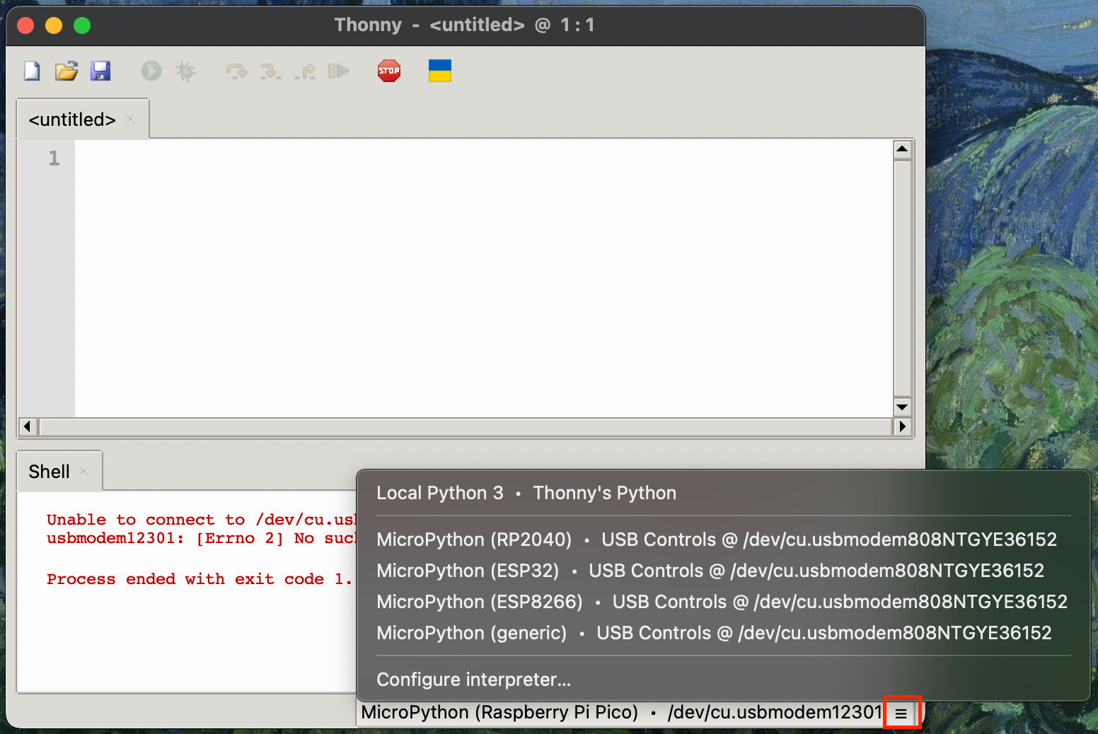
-
Choose the board and port at the right bottom corner.

-
You can hit the green play button now, it will be blinking!
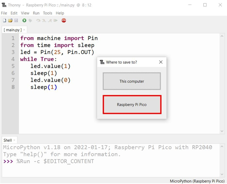
-
After testing the code and you are happy about it, save the code as
main.pyon Raspberry Pi Pico.
-
Pico will run any code named
main.pyautomatically whenever it is powered. But remember to save a file with an identifiable file name on your computer, otherwise you will end up with a bunch ofmain.pywithout knowing what they do. -
At this point, you don't need your computer anymore. You can power the Pico with a phone charger or battery.
What are GPIO pins on Raspberry Pi?
What is GPIO?
GPIO stands for General-Purpose Input/Output. GPIOs have no predefined purpose and are unused by default. If used, the purpose and behaviour of a GPIO are defined and implemented by the user. You can find the GPIO pins on the top of most Raspberry Pi models or other microcontrollers such as Arduino.
GPIO pins are mostly used for connecting electronics with computers/microcontrollers. These components can then be programmed to perform different tasks using different languages, such as C++, Python and Scratch. In this tutorials, we will focus on the GPIO pins on Raspberry Pi.
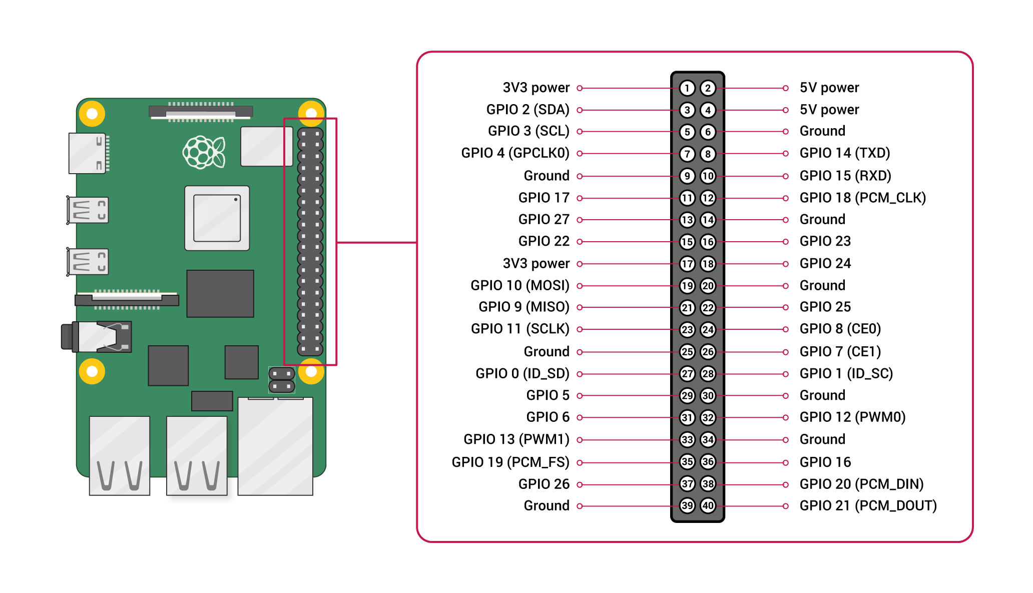
Numbering of GPIO pins
GPIO pins on Raspberry Pi have two numbering systems, Board and Boardcom (BCM). For example, the board pin 8 and BCM pin 14 are referring the same pin. Numbering is important based on which programming languages and libraries you use.
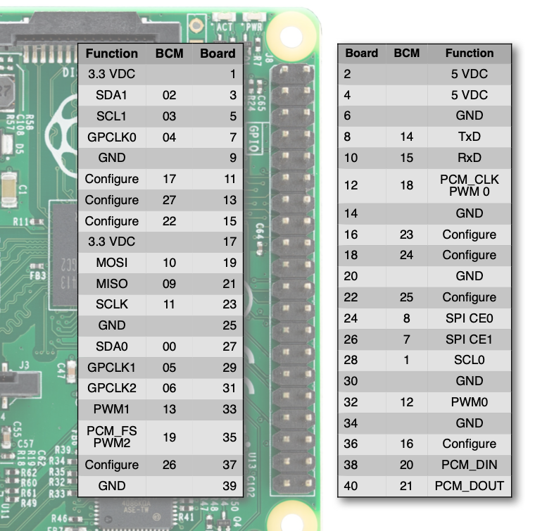
1. BCM numbering
BCM numbering matches up with the tiny labels printed on the Raspberry Pi, like GPIO14. It is used in most programming languages such as Python and Scratch.
2. Board numbering
Board numbering is based on the physical locations of the pins on the Raspberry Pi. It starts from the top left corner as Pin 1, left to right then next line, and the bottom right will be the last pin, Pin 40. Board numbering is less common to be used, the only place you will see is probably in one or two Python libraries.
3. Functionalities of the Pins
Each pin on the pi has different functions and their physical locations may move from model to model. The pins without a BCM number are power output pins, such as GND and 5VDC. Pins with a BCM number are all PWM pins which can be used as input or output. Besides being a PWM pin, they also have other unique functions, such as GPIO 02 and GPIO 03 are also the pins of SDA and SCL for I²C communication. You can refer to the pinout of each model to find out more details of each pin.
Building Circuit with Raspberry Pi
UNPLUG your Pi when you are connecting electronics and DOUBLE CHECK your connections!Raspberry Pi is not short-circuit-proof as Arduino. If you have a short circuit or you give more power than it could take to the GPIO pins, it will break the Pi.
You will probably need a breadboard to make connections easier. In general, I will not suggest direct soldering on a Raspberry Pi, so it can be reused more easily. You can also use a jumper cable to extend all pins to a breadboard.
Popular GPIO libraries with Python
There are many options to program a Raspberry Pi with physical computing components, including Scratch, Bash, Node.js, C etc. We will focus on Python here. Below are two codes using two different libraries but doing the exact same thing.
1. gpiozero
The main thing to remember about gpiozero library is that it focuses on buttons and LED instead of the actual GPIO pins. i.e. LED = OUTPUT, button = INPUT. Some people may find the syntax easier to understand, like turning on the LED is literally leds.on(). gpiozero is simple and quick and it's a great place to start experimenting as a beginner. But if you are not actually using LEDs or buttons, it can be a bit confusing and it is not very compatible to merge with codes from other libraries as well. Find its documentation here.
# example of programming Raspberry Pi GPIO with gpiozero
# refer to gpiozero.readthedocs.io
import gpiozero as gpzero
from time import sleep
# set up pushbutton and bank of leds
resetbutton = gpzero.Button(3)
leds = gpzero.LEDBoard(26,16,20,21)
# functions to control behavior
def LightsOn ():
while resetbutton.is_pressed:
leds.on()
def ResetCounter ():
global counter
leds.off()
counter = 0
def binary2lights(showThis):
leds.value = (
showThis & 0b1000,
showThis & 0b0100,
showThis & 0b0010,
showThis & 0b0001)
# setup button handlers
resetbutton.when_pressed = LightsOn
resetbutton.when_released = ResetCounter
# send 0...15 to lights
while True:
ResetCounter()
while counter < 16:
binary2lights(counter)
counter += 1
sleep(1)
2. RPi.GPIO
Borken Library!This library is currently not usable for Raspberry Pi 5. If you are using Pi 4 or older, it will be fine.
RPi.GPIO is a code library that allows Python to communicate with the GPIO. It is widely used and supported. In fact, gpiozero is developed based on RPi.GPIO. I find this library closer to C++ in Arduino IDE. For example, instead of on() and off(), it uses HIGH and LOW. Find its documentation here.
# example of programming Raspberry Pi GPIO with rpi.gpio
# refer to sourceforge.net/p/raspberry-gpio-python/wiki/Home
import RPi.GPIO as GPIO
from time import sleep
GPIO.setmode(GPIO.BCM) # declare BCM numbering scheme (vs GPIO.BOARD)
# set up pushbutton and bank of leds
resetbutton = 3
leds = [26, 16, 20, 21]
GPIO.setup(3, GPIO.IN)
GPIO.setup(leds, GPIO.OUT)
# function to handle reset button
def handleReset ():
while not GPIO.input(resetbutton):
GPIO.output(leds, GPIO.HIGH)
print("waiting for button")
resetLightsandCounter()
def resetLightsandCounter():
global counter
GPIO.output(leds, GPIO.LOW)
counter = 0
print("reset")
# setup button handlers
GPIO.add_event_detect(resetbutton, GPIO.FALLING)
# send 0...15 to lights
while True:
resetLightsandCounter()
while counter < 16:
if GPIO.event_detected(resetbutton):
handleReset()
GPIO.output(leds, (
GPIO.HIGH if counter & 0b1000 else GPIO.LOW,
GPIO.HIGH if counter & 0b0100 else GPIO.LOW,
GPIO.HIGH if counter & 0b0010 else GPIO.LOW,
GPIO.HIGH if counter & 0b0001 else GPIO.LOW
)
)
counter += 1
sleep(1)
Raspberry Pi Image
How to image a Raspberry Pi
How to image a Raspberry Pi?
There is an official video showing how if you prefer.
1. Download the Raspberry Pi Imager
Go to the Raspbeery Pi official site to download the software. Choose a suitable version for yourself.

2. Insert your SD card
A CTL Pi kit should contain an SD card. Insert the SD card into your computer. It is always a good habit to format the SD card before imaging it. You need the SD card to be in FAT32 format.
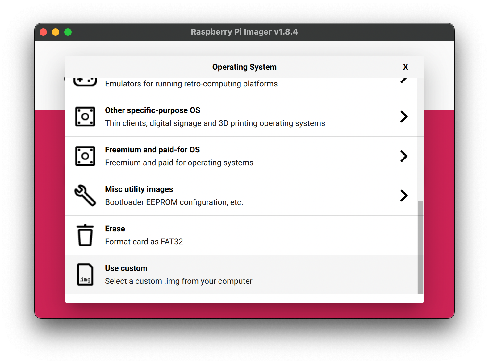
Open Raspberry Pi Imager v1.8.4, you can format the SD card directly.
-
Storage, select the SD card -
Operating System-Erase
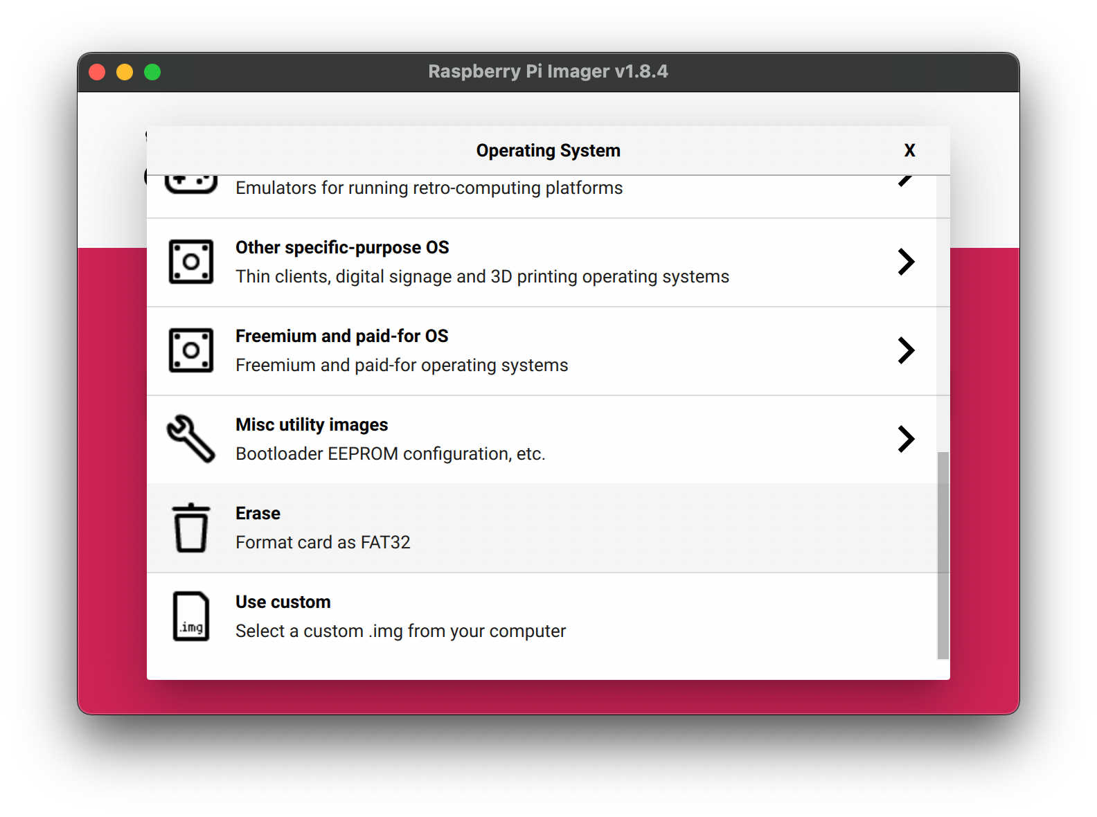
- Click
Nextand wait for it to finish.
3. Image your Pi
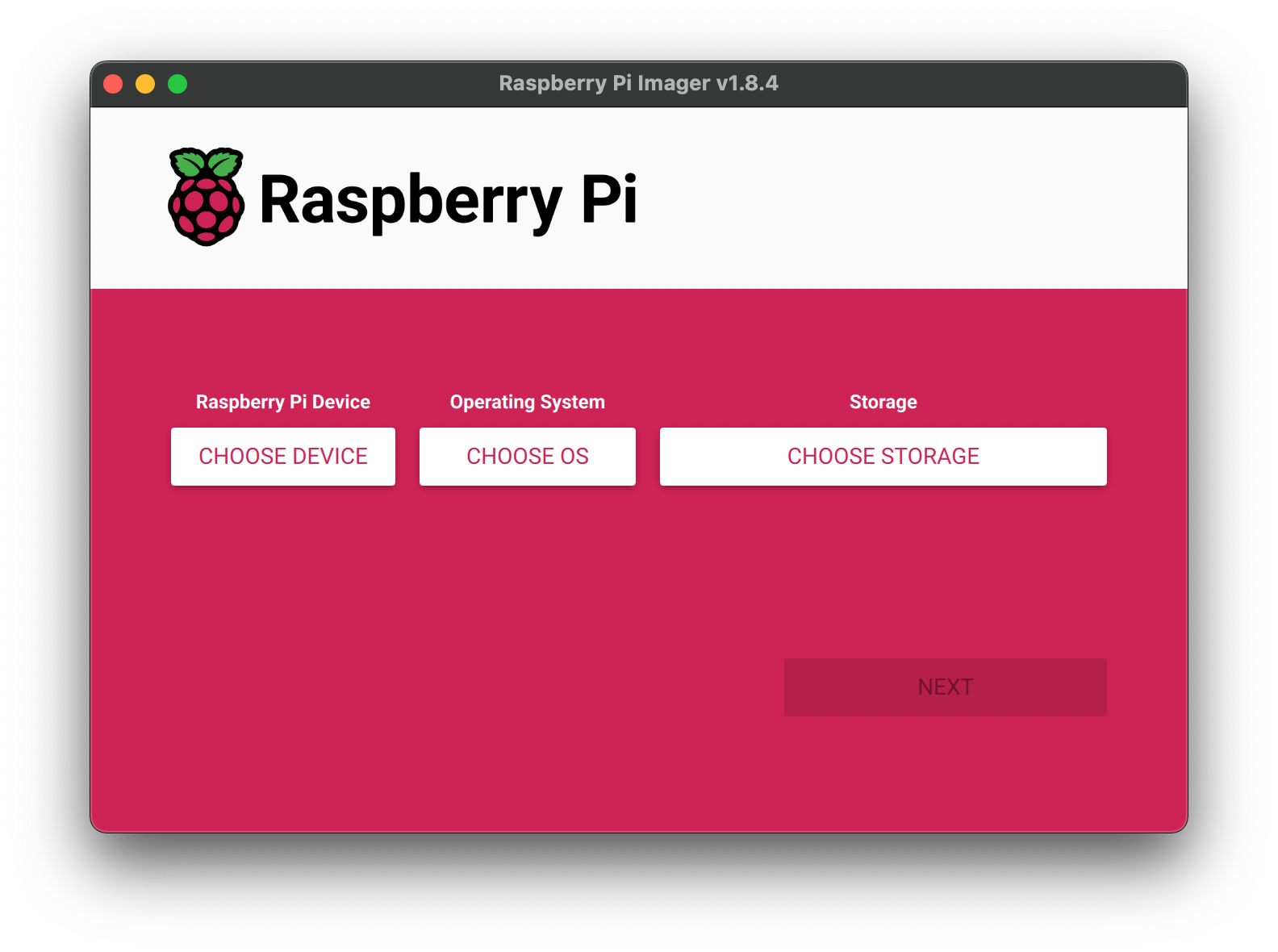
Using Raspberry Pi Imager software to Install the Raspberry Pi OS to the SD card.
-
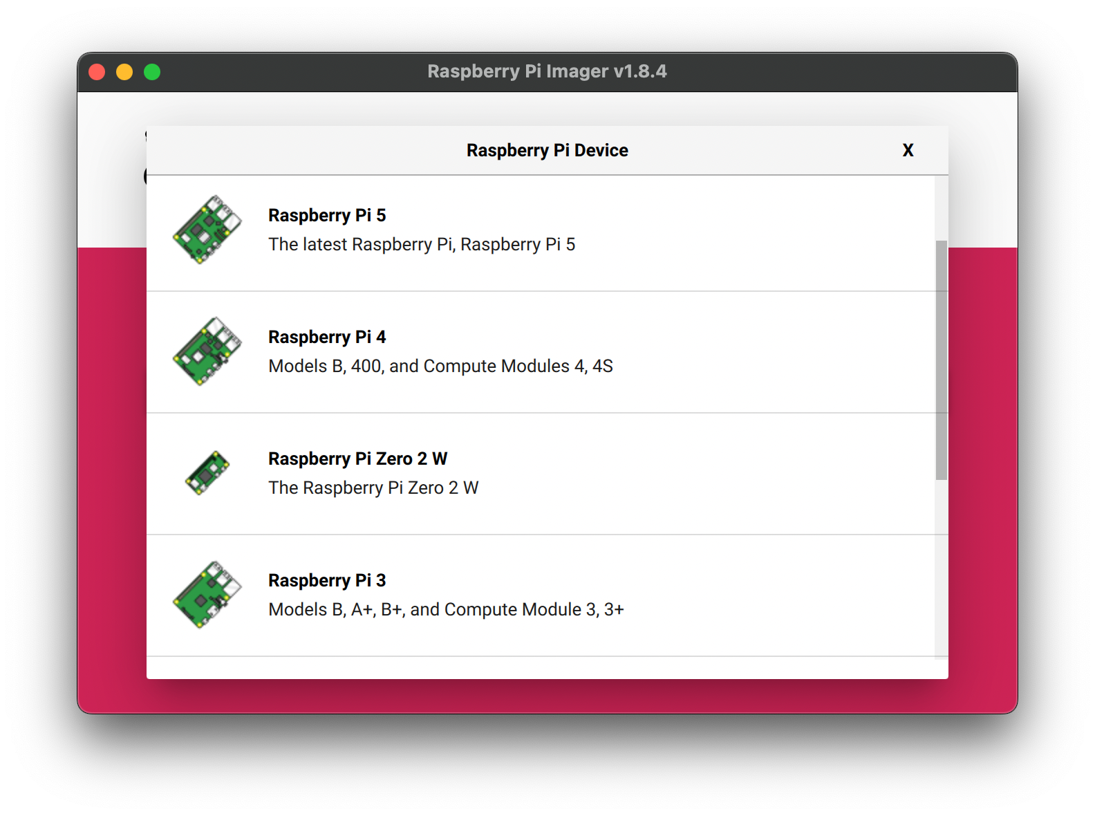
Raspberry Pi Device, select Raspberry Pi Model
-
Operation System, select Raspberry Pi OS, if you are not sure which to choose, choose the recommended one.
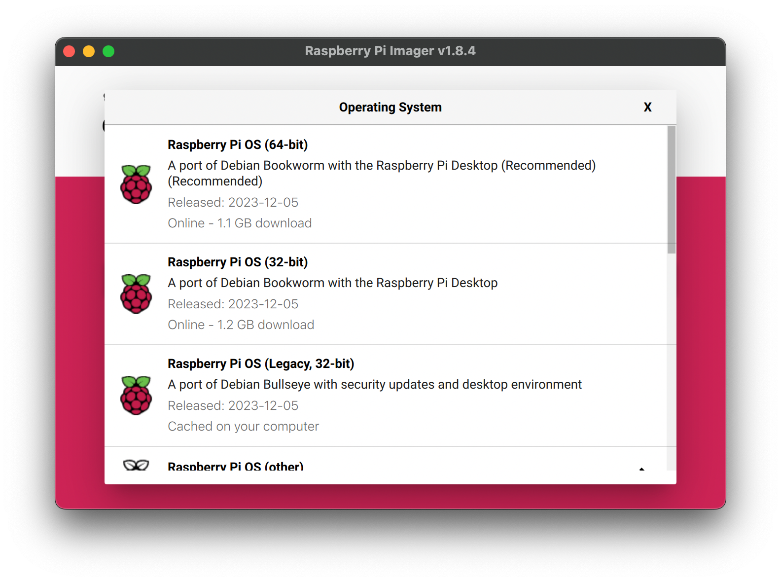
-
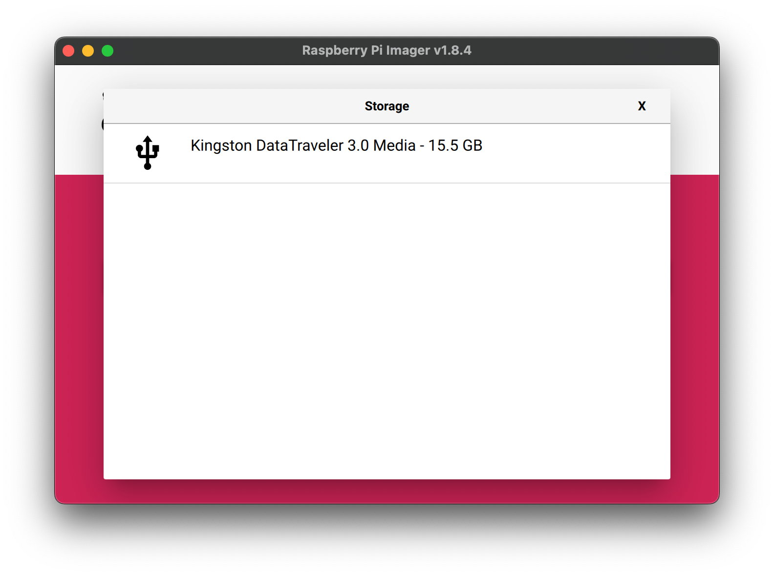
Storage, select the SD card
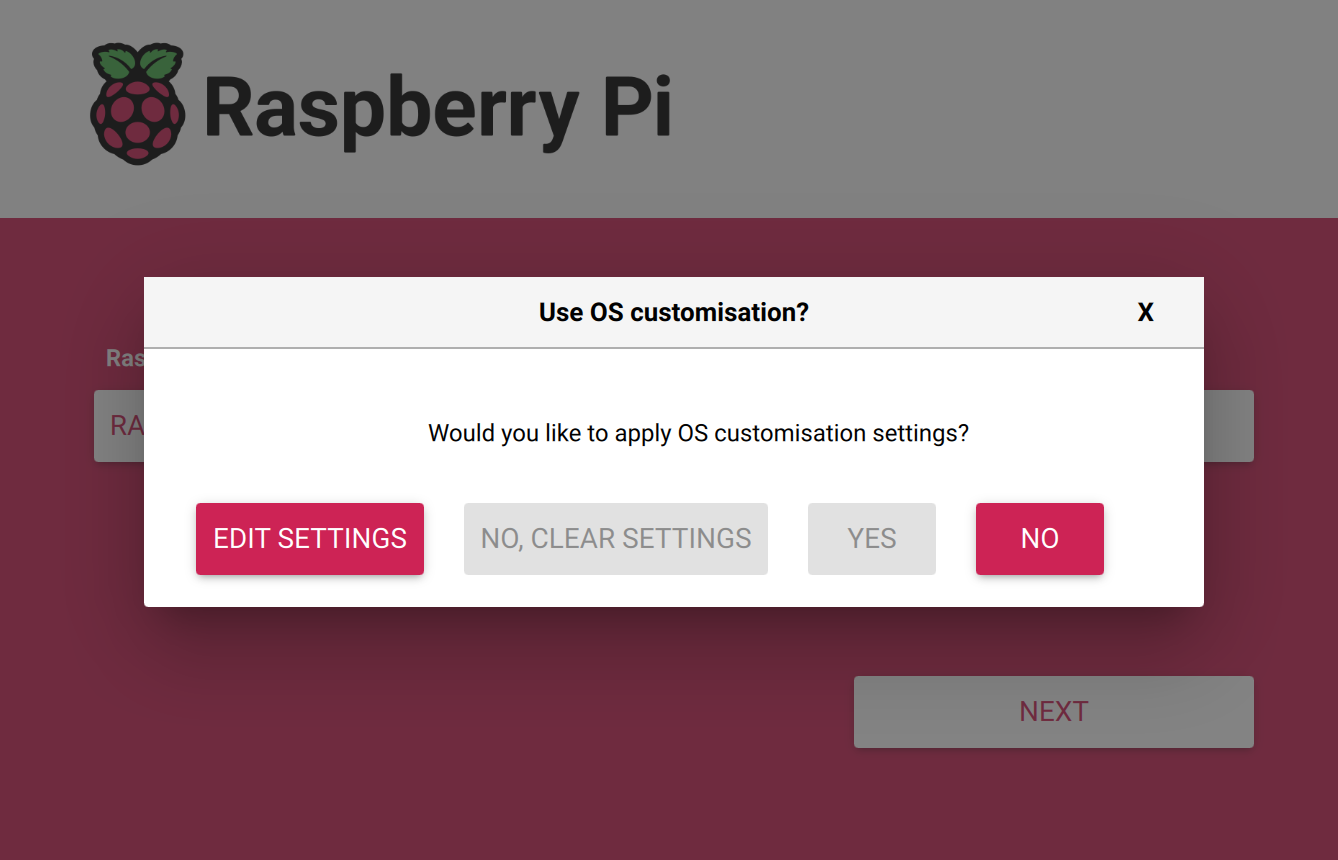
- Click
Next, then you will be prompted with "Would you like to apply OS customisation settings?", and chooseNO.
Once the pi is imaged, it is a ready to go mini computer. Eject the SD card from your computer, plug it into the Pi, power the Pi, it's done!
Raspberry Pi Image: Retropie for Reviving Vintage Games
What is Retropie?

RetroPie allows you to turn your Raspberry Pi into a retro-gaming machine. It builds upon Raspbian, EmulationStation, RetroArch and many other projects to enable you to play your favourite Arcade, home console, and classic PC games with the minimum set-up. Learn more.
RetroPie sits on top of a full OS, you can install it on an existing Raspbian, or start with the RetroPie image and add additional software later. It's up to you.
We are using Raspberry Pi Imager. We have a more detailed tutorial for imaging the Pi.
1. Using Raspberry Pi Imager
-
Raspberry Pi Deviceselect Raspberry Pi Model -
Storageselect the SD card
-
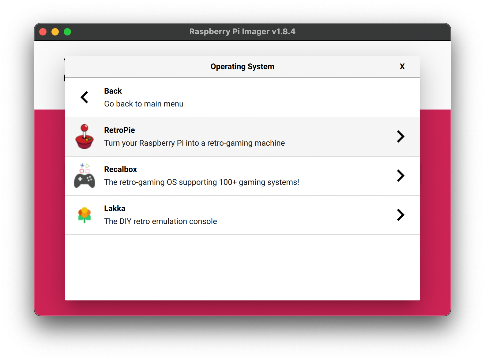
Operation System- selectEmulation and game OS- selectRetroPie- select your Pi model
Your Pi is now an emulator ready to go!
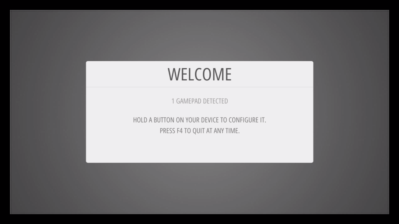
2. Controller Configuration
RetroPie can support a range of controllers and even arcade buttons and joysticks. PS5 controller is not supported at the moment(02/2024). You will see the Welcome page, plug in your controller with a USB cable and hold any button on your device.
Press the buttons on your controller accordingly, one by one.
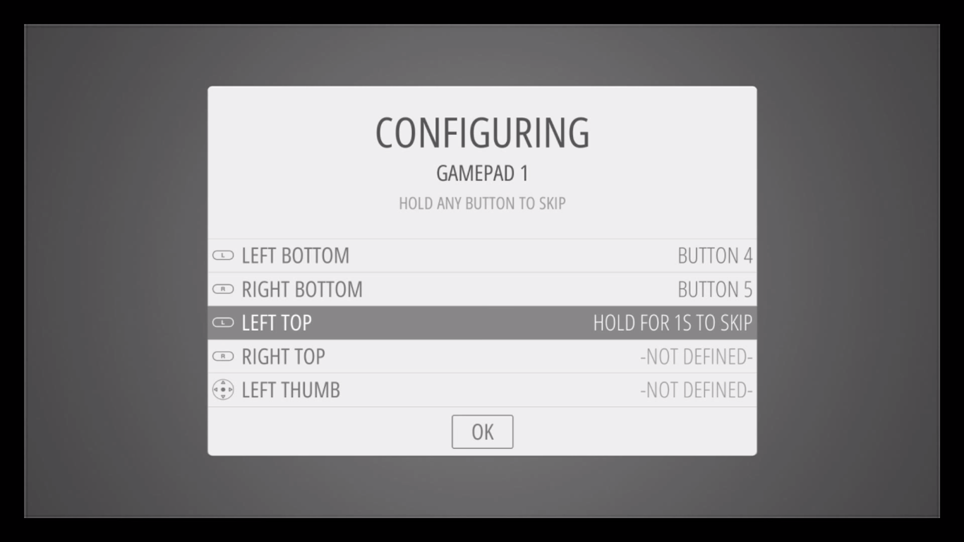
If you want to skip any button configuration, just hold any button.
There are some buttons that you MUST set up, including Hotkey, Start, Select, A and B.
3. Finding Roms
ROM is Read Only Memory, which can be seen as games that can be run on emulators. Thanks to the generosity of some of the original creators of the classic games that MAME® can emulate, several games have been released for free, non-commercial use on MAMEdev. The copyright laws around the use of ROMs are mostly between illegal and grey areas, so no suggestion on where to download ROMs will be provided in this tutorial and no one on our team will answer you in person either.
Different emulators require different file extension so the ROMs can be read properly, such as GBA needs .7z, .gba or .zip. Please see more ROM file formats here.
4. Transferring Roms
Transferring via a USB stick is the most straightforward method. You can find other ways of transferring in RetroPie Docs.
- Format the USB stick as FAT32. (You can refer to #2 of this tutorial.)
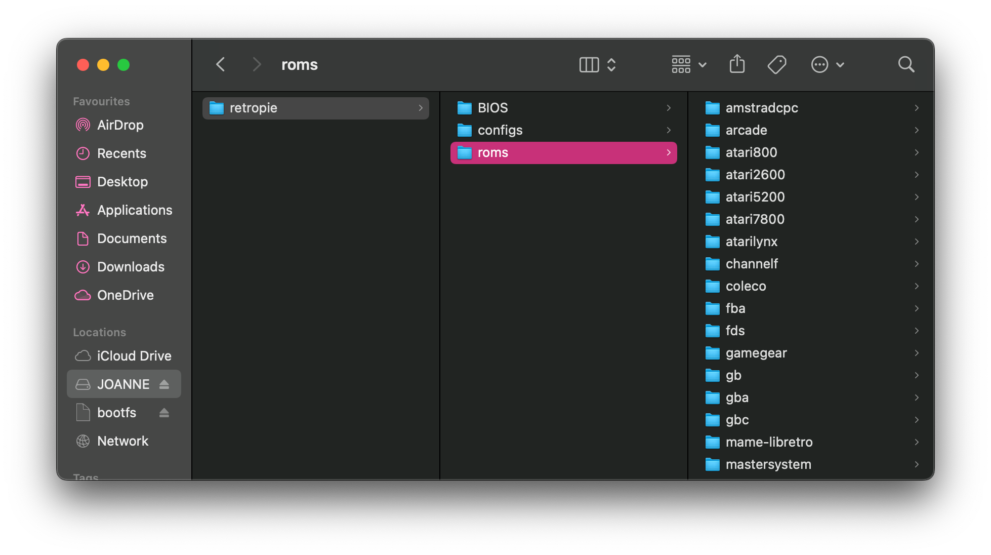
- Create a folder called
retropieon the USB stick. - Plug the USB stick into the Pi and wait for 5-10 minutes.
- Remove the USB stick and plug it into your computer.
- You should see
retropie/roms/, the Pi has created all the necessary folders for you in the USB stick.
- Copy the ROMs to the according folder. For example, you can copy the MAME ROMs in
retropie/roms/mame-libretro - Plug the USB stick back into the Pi, and wait for 5-10 minutes again.
- Refresh the game listing in EmulationStation by pressing press Start on your controller -
Quit-Restart Emulation Station - Now you should your game showing on the Pi and you can start playing your game!
- If not, please go back to step 7 and do it again.
5. Want more?
RetroPie can be customized to a high extent, including controllers, UI, cheats, shaders etc.
For more detailed documentation, please visit RetroPie Docs.
Raspberry Pi Image: Video Looper
What is Raspberry Pi Video Looper?
Raspberry Pi Video Looper is a simple way to display seamless looping video files, for example in an art exhibition. All you need is a Raspberry Pi, an SD card, a screen and a USB stick.
We are using Raspberry Pi Imager. We have a more detailed tutorial for imaging the Pi.
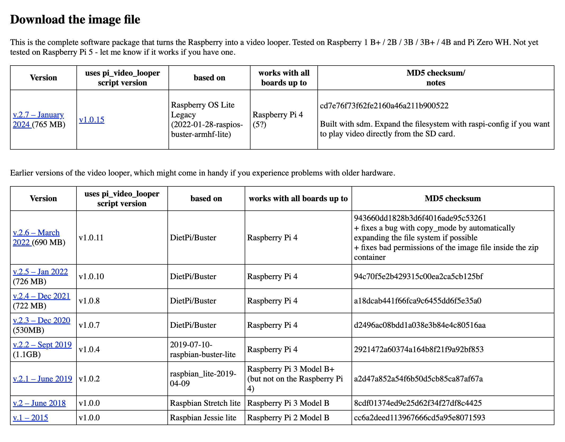
1. Download the Video Looper Image
You can download the Video Looper image here. Choose the latest version that is compatible with the Pi model you are using, please refer to the "works with all boards up to" column.
2. Using Raspberry Pi Imager
Raspberry Pi Deviceselect Raspberry Pi ModelStorageselect the SD card
Operation System- selectUse custom- select the newly downloaded Video Looper Image
3. Files Format
Video Looper uses the default video player, omxplayer, which can play most videos encoded with the H.264 video codec and in a video format with an extension like .avi, .mov, .mkv, .mp4, or .m4v.
Try to minimize the size of your files and export the video with the exact resolution of your display for better performance. e.g. You shouldn't use an uncompressed 4K video format on a 1080p HD display.
4. Plug and Play
You can put your video on a USB stick and plug it to the pi. Your video(s) is ready to loop!
If only one movie is available it will play continually in a loop.
If multiple movies are found then each movie will be played in alphabetical order by filename and will loop back to the first video and play all videos again in order repeatedly.
5. Note on Raspberry Pi Monitors
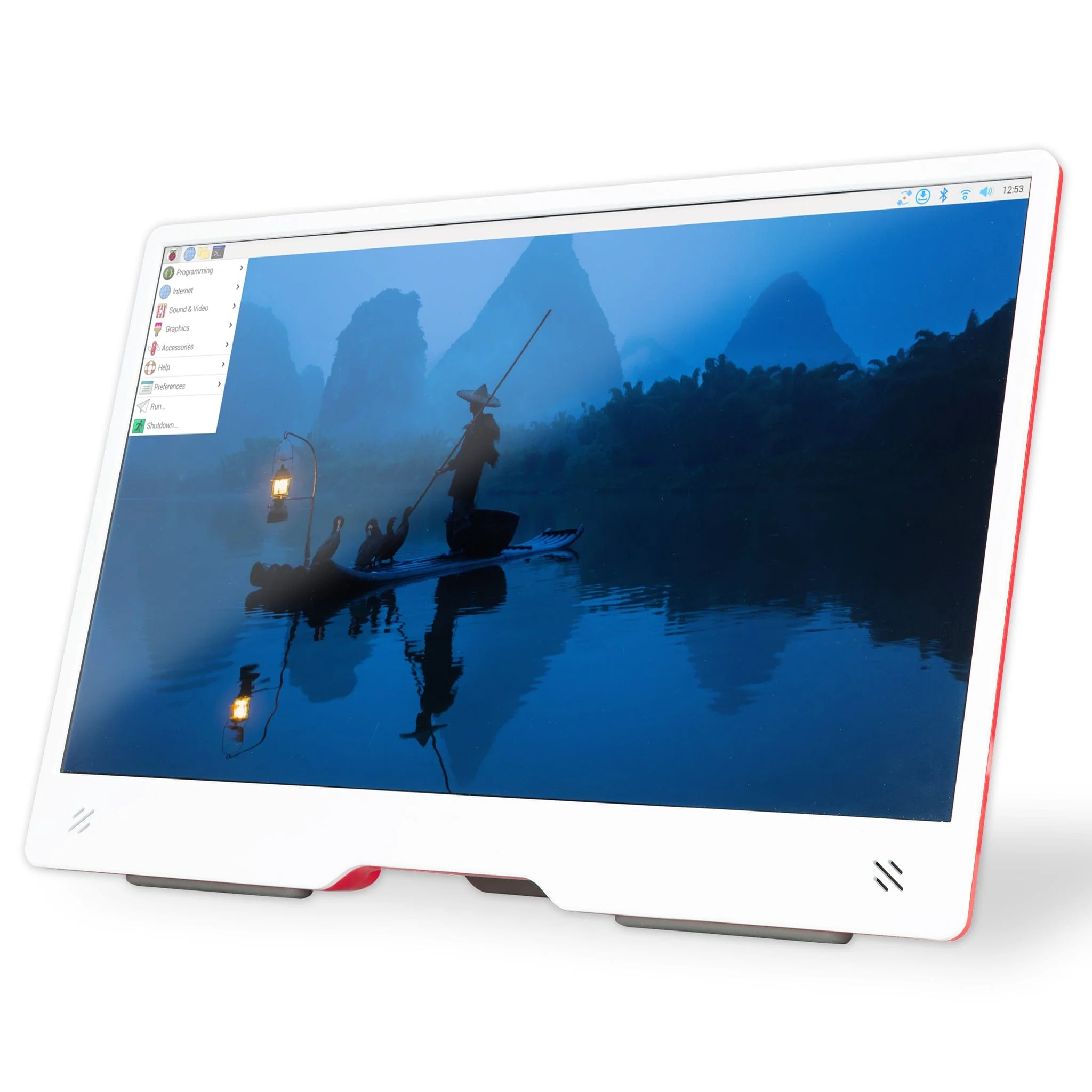
If you are using Video Looper OS with a Raspberry Pi Monitor (shown above) you may notice that the monitor will go to sleep rather than display the video. There is an extra setup step required to fix this.
- Open the MicroSD card on your computer/laptop with the Video Looper OS installed. It should appear as a drive with the name
boot. - Place this config.txt in the top-level folder. There is already a config.txt file in the drive, but this new one has the right settings that will encourage the display to wake up. When you are asked if you wish to overwrite the existing file, click Yes/Confirm.
- Place the MicroSD card back in the Raspberry Pi.
The Video Looper OS should now work with the monitor and run with a 1920x1080p resolution.
How to Configure a Raspberry Pi for the first time
Once your Raspberry Pi is imaged, it is ready to go! We have a more detailed tutorial for imaging the Pi. Now we can move on to configuration when you turn on your Pi for the first time.
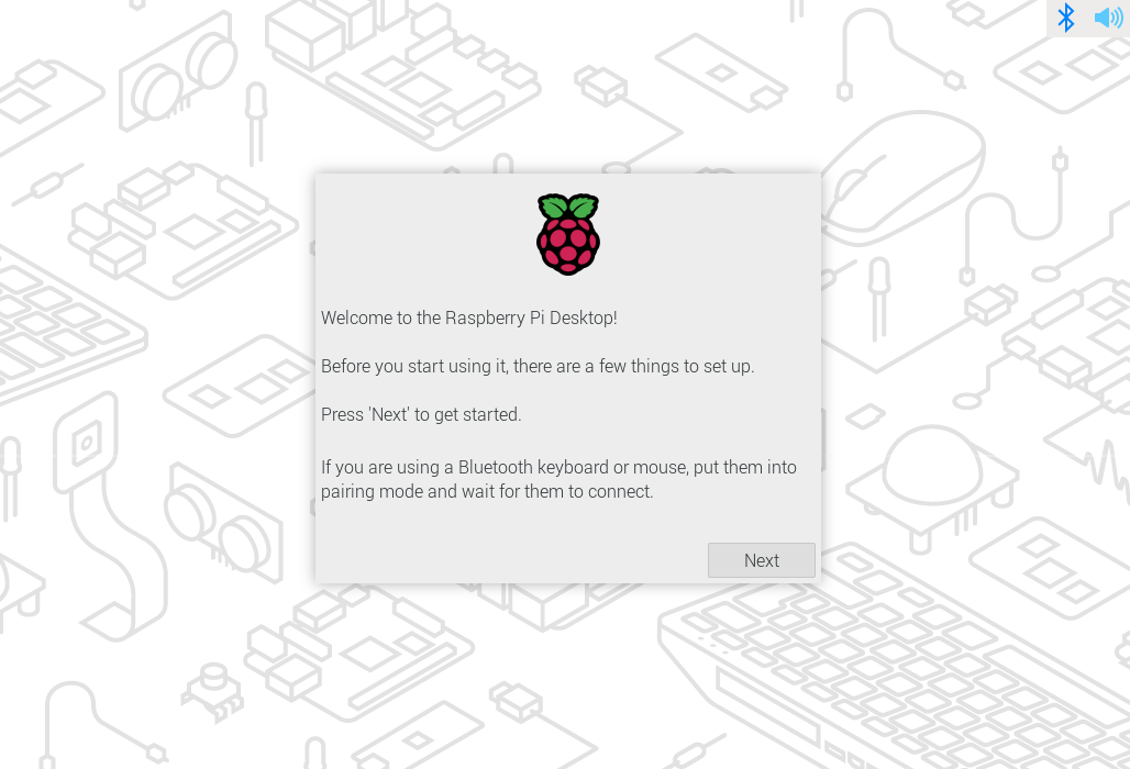
1. Power up the Raspberry Pi
When you plug in the power supply and all other equipment you need, the Pi should start booting automatically. If your Raspberry Pi does not turn on within 5 minutes, check the status LED, and try re-image the SD card.
If everything goes right, you should see this.
2. Locale
You need to set your country, language, time zone, and keyboard layout.
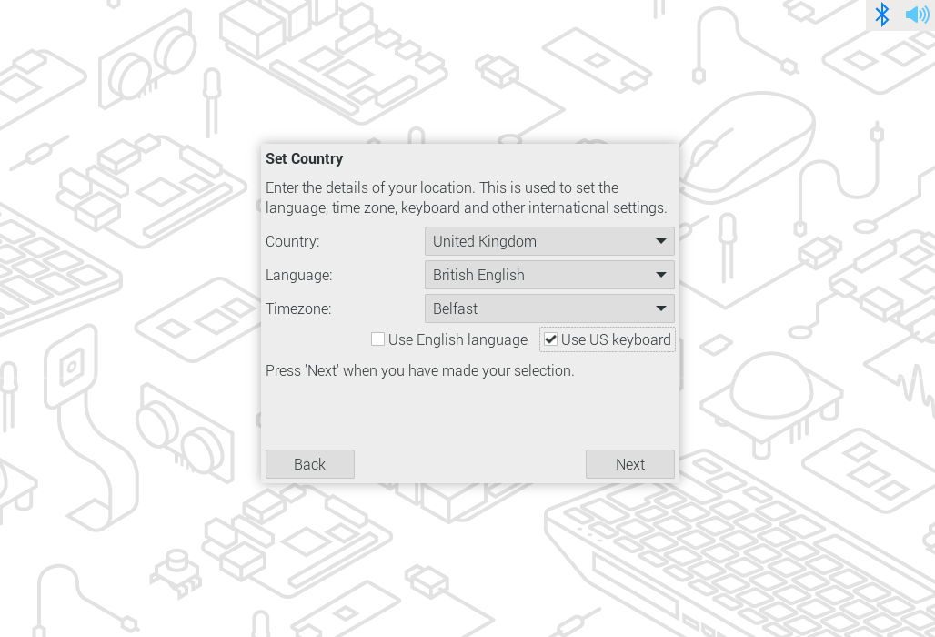
When you are setting up the keyboard, make sure the keyboard is plugged in. If you uncheck the Use US keyboard, it will set up the keyboard corresponding to your Country. The main difference between US and UK keyboards is the positions of @,", £ and #. There are many variants of keyboards, even just for US/UK keyboards. You can change that after the initial setup. Check this tutorial for changing the keyboard layout.


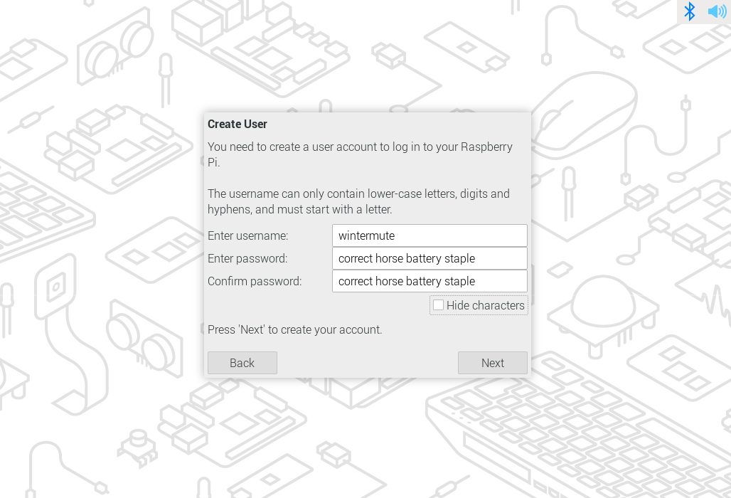
3. User
You can set your username and password here. For some older Raspberry Pi OS, it has a default username and password, which is username: [ pi ] ; password: [ raspberry ].
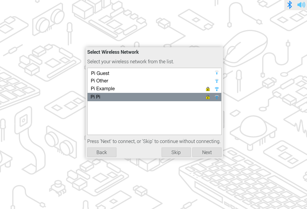
4. Wifi
You can log in to the WIFI as usual with SSID and password. For some networks, such as UAL wifi, you need to sign in with your UAL account, which will not work for most Pi. In that case, you will need an Ethernet cable to access to the internet.
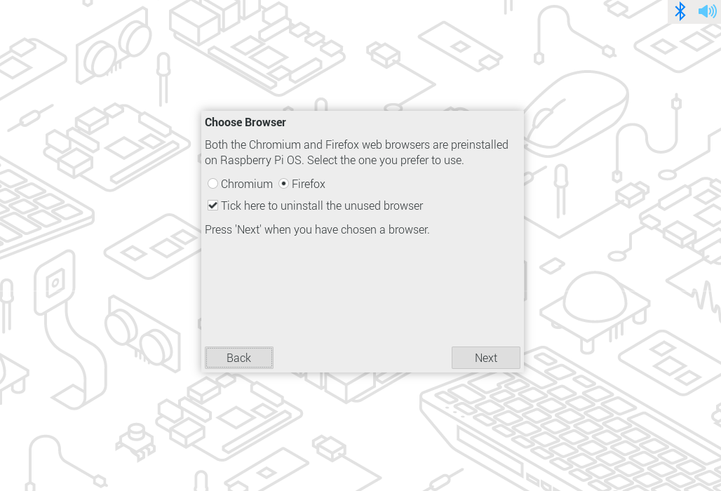
5. Brower
Google Chrome and Firefox are both preinstalled, you just need to choose one as your default browser. You can still access the other run from the start menu.
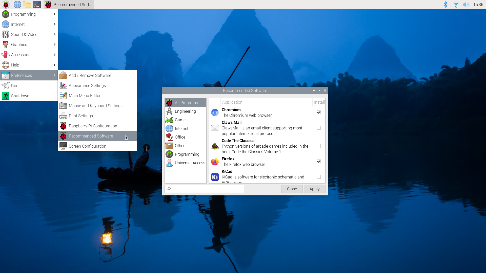
6. Recommended Software
Raspberry Pi comes with many essential applications pre-installed so you can start using them straight away, such as Thonny. You can go to Start - Preference - Recommended Software, explore the list and download the ones you need.
Tutorials
How to make the Raspberry Pi display a web page fullscreen at power on
This short tutorial should be enough for you to be able to setup a Raspberry Pi with GUI mode and auto login enabled to disable a web page full screen automatically when it turns on.
- Copy
full-screen.shinto the home folder of the pi user, and run the following command:/home/pi/full-screen.sh
sudo chmod +x full-screen.sh
full-screen.sh
export DISPLAY=:0.0
xset s off
xset -dpms
xset s noblank
chromium-browser --noerrdialogs --kiosk https://google.co.uk --incognito
- Create a folder called autorun inside the
.configfolder of the home folder of the pi user:/home/pi/.config/autorun/kiosk.desktop
cd /home/pi/.config
mkdir autorun
kiosk.desktop
[Desktop Entry]
Type=Application
Exec=/home/pi/full-screen.sh
Hidden=false
X-GNOME-Autostart-enabled=true
Name=kiosk
- Reboot the Raspberry Pi.
sudo reboot now
How to power the Raspberry Pi Pico
Powering the Raspberry Pi Pico
The easiest way to power a Pico is through the USB cable either to a computer or a phone charger. If you are going for a wireless design, you can use batteries as well. This tutorial will demonstrate how to power a Pico with a 9V battery or 3 AA batteries.
Raspberry Pi Pico pinout
You have to find out the pinout of the model you are using. The pins you are looking for are VSYS and GND. In this tutorial, a Pico W is used.
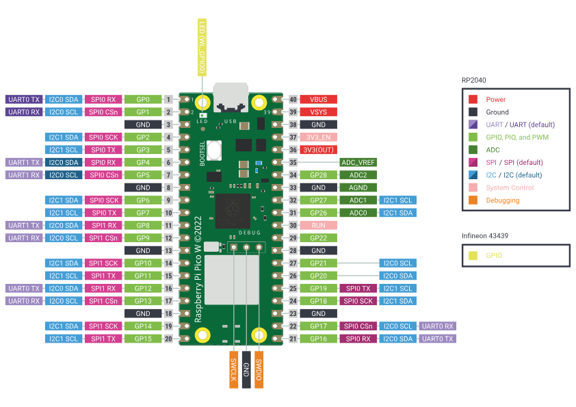
Raspberry Pi Pico's Power Need
VSYS (PIN 39): Pin for main system input voltage. The input voltage can vary between 1.8V to 5.5V. This voltage is used by the onboard SMPS to generate 3.3V to power the RP2040 microcontroller and GPIOs.
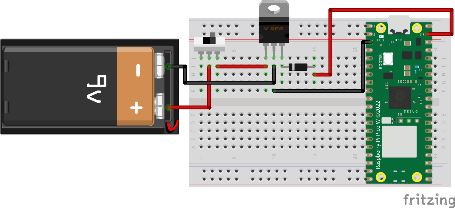
Why these parts are needed
-
Switch: When we are using batteries to power the microcontroller, a switch is preferred. Some battery holder has a built-in switch which will be more convenient for you. With a switch, you can turn off the Pico when not in use and not drain the battery.
-
LM7805: The LM7805 is a popular voltage regulator integrated circuit (IC). It is a positive voltage regulator that provides a stable and fixed output voltage of +5 volts. It is widely used in electronic circuits to regulate the voltage and ensure a consistent and reliable power supply. It can accept an input voltage in the range of 7V to 35V, depending on the specific model, so you will need this when you are using a power supply with a voltage higher than 5V.
-
Diode: - A diode is a semiconductor device that allows current to flow in one direction while blocking it in the opposite direction. In other words, it acts as a one-way valve for electric current. We need a diode for safety to prevent one power source from back-feeding the other. Raspberry Pi can have two power sources at the same time and there is a risk of unwanted power flow between the two power sources. Schottky diode is preferred for its low voltage drop, but any others should work with a bit of voltage drop around 0.2-0.6V.
9V battery
Part needed: switch, LM7805 & Any diode
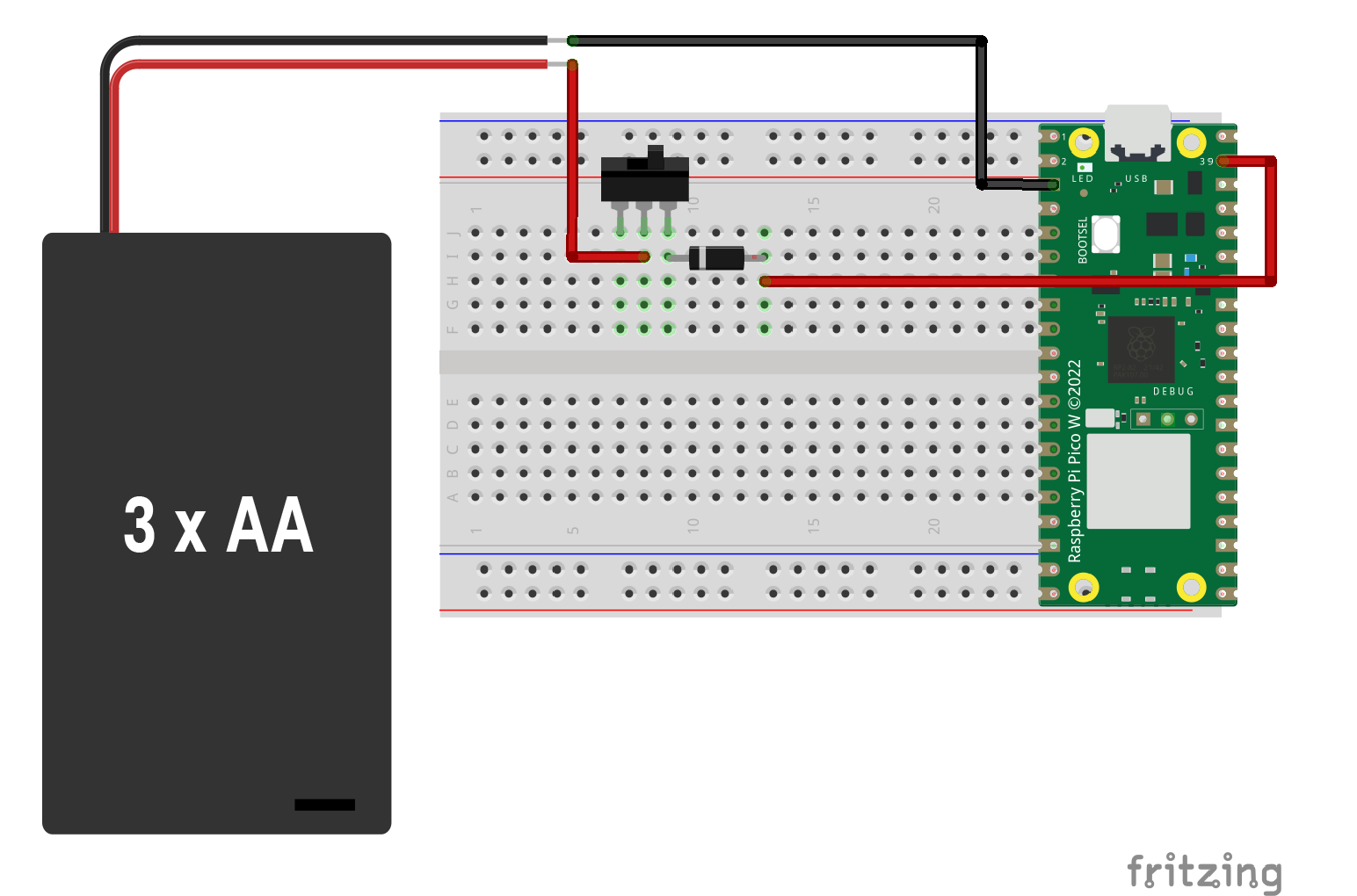
3 AA batteries
Part needed: switch & Any diode
How to make two Raspberry Pi Pico communicate via Wifi
Wifi Communication
Before heading to communication between two pico, you can try controlling pico via wifi with your computer first, see tutorial here.
Server Code
Client Code
How to control Raspberry Pi Pico via Wifi
What is Wifi
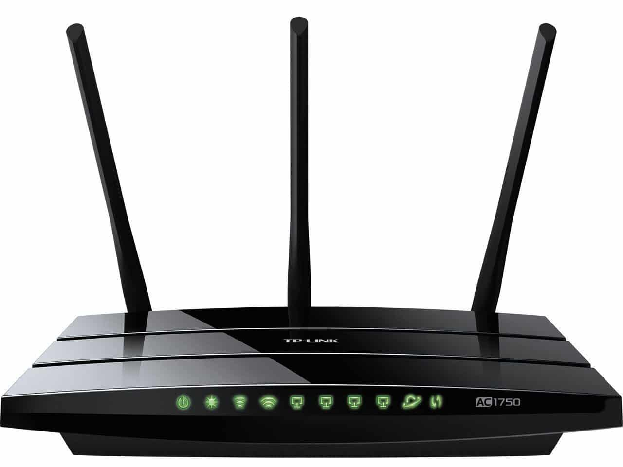
WiFi, short for Wireless Fidelity, is a technology that enables devices like smartphones, laptops, and other electronic gadgets to connect to the internet or communicate with each other without the need for physical cables. It operates by using radio frequency signals to transmit data between devices and a wireless router. The router, connected to the internet via a wired connection, acts as a central hub that facilitates communication between devices within its range. WiFi has become a ubiquitous and convenient way for people to access the internet and share information wirelessly, contributing to the proliferation of wireless connectivity in homes, businesses, and public spaces.
You can create a local wifi network with just powering up a wifi router. When two or more devices (computers, microcontrollers...) are connected to the same wifi network, they can communicate with each other, without accessing the internet. Not all microcontrollers come with a built-in Wifi module so we will be using Pico W (with a built-in wifi module) in this tutorial. But there are plenty of add-ons options you can add to your microcontroller for wifi.
External read for fun:)
What is IP address
An IP address, or Internet Protocol address, is a unique numerical label assigned to each device connected to a computer network that uses the Internet Protocol for communication. It consists of a series of numbers separated by periods, like xxx.xxx.xxx.xxx. Think of it as a digital address for your device on the internet. It allows devices to identify and communicate with each other on a network, much like a home address allows mail to be delivered to a specific location. IP addresses can be dynamic, meaning they change periodically, or static, where they remain constant. They play a crucial role in routing data packets across the internet, ensuring that information reaches the correct destination.
How to find my IP address
- Google Search - "What's my IP address?"
- Go to Network Preferences (MAC), Wifi Properties (Windows)
- Go to Terminal (MAC) or Command Prompt (Windows) and type in
ipconfig getifaddr en1
Get started
The example code will turn on/off the onboard LED on Pico via wifi without an external circuit. See this tutorial to learn how to set up your Pico. Before you go ahead, there are some things that you need to change for your wifi.
- Change
ssid,passwordin the code - Run your code in Thonny
- Find your
IP addressin the Thonny Shell, something likeip = 10.3.15.120 - open up a web browser
- go to
http:// **IP address**/light/onto turn the LED on - go to
http:// **IP address**/light/offto turn the LED off
import network
import socket
import time
from machine import Pin
led = Pin("LED", Pin.OUT)
ssid = 'YOUR NETWORK NAME'
password = 'YOUR NETWORK PASSWORD'
wlan = network.WLAN(network.STA_IF)
wlan.active(True)
wlan.connect(ssid, password)
html = """<!DOCTYPE html>
<html>
<head> <title>Pico W</title> </head>
<body> <h1>Pico W</h1>
<p>%s</p>
</body>
</html>
"""
max_wait = 10
while max_wait > 0:
if wlan.status() < 0 or wlan.status() >= 3:
break
max_wait -= 1
print('waiting for connection...')
time.sleep(1)
if wlan.status() != 3:
raise RuntimeError('network connection failed')
else:
print('connected')
status = wlan.ifconfig()
print( 'ip = ' + status[0] ) //print your address
addr = socket.getaddrinfo('0.0.0.0', 80)[0][-1]
s = socket.socket()
s.bind(addr)
s.listen(1)
print('listening on', addr)
# Listen for connections
while True:
try:
cl, addr = s.accept()
print('client connected from', addr)
request = cl.recv(1024)
print(request)
request = str(request)
led_on = request.find('/light/on')
led_off = request.find('/light/off')
print( 'led on = ' + str(led_on))
print( 'led off = ' + str(led_off))
if led_on == 6:
print("led on")
led.value(1)
stateis = "LED is ON"
if led_off == 6:
print("led off")
led.value(0)
stateis = "LED is OFF"
response = html % stateis
cl.send('HTTP/1.0 200 OK\r\nContent-type: text/html\r\n\r\n')
cl.send(response)
cl.close()
except OSError as e:
cl.close()
print('connection closed')
How to set the sound output in Raspberry Pi
Audio Setting
Most Raspberry Pis have a 3.5mm audio jack for outputting audio, but you can also output audio via HDMI as well. The below will show you two different ways to set the output device.
Method 1: Use Raspberry Pi Configuration (GUI)
- Click the Raspberry menu (top-left corner)
- Go to Preferences → Audio Device Settings
- In the Output Device dropdown, choose:
HDMIorHDMI 1(depending on your Pi model) - Click Select Controls if needed to unmute or adjust volume
- Click Close
You may not see the exact thing on your pi based on the operating system you used.
Method 2: Terminal Command
For example, setting HDMI as default audio output:
amixer cset numid=3 2
The 2 at the end indicates HDMI.
- 0 = Auto
- 1 = Analog (3.5mm jack)
- 2 = HDMI
Method 3: Use raspi-config
-
sudo raspi-config - Navigate to:
1. System Options → S2 Audio - Choose:
1 HDMI(or HDMI 1 if you see multiple) - Press Enter, then Finish
Test the Audio
- You can test it with:
speaker-test -t sine -f 440 -c 2 - Or play a WAV sound file:
aplay /home/pi/Music/youOwnSoundFile.wav - Or play a MP3 sound file:
cvlc /home/pi/Music/youOwnSoundFile.mp3
How to install Node.js on Raspberry Pi
Installing Node.js on Raspberry Pi is very simple for those with basic command line experience.
In the terminal or via SSH:
- Add the package source:
curl -sL https://deb.nodesource.com/setup_10.x | sudo -E bash - - Install Node using:
sudo apt-get install -y nodejs - Confirm package is installed:
node -v
Extra steps
You may also wish to install the development tools to build native addons:
sudo apt-get install gcc g++ make
And you may wish to install Yarn package manager to replace NPM:
curl -sL https://dl.yarnpkg.com/debian/pubkey.gpg | sudo apt-key add -
echo "deb https://dl.yarnpkg.com/debian/ stable main" | sudo tee /etc/apt/sources.list.d/yarn.list
sudo apt-get update && sudo apt-get install yarn
How to use Waveshare E-Paper Display with Raspberry Pi
What is a Waveshare E-Paper Display?
In this tutorial, we will be using the Waveshare model epd7in5V2, a Raspberry Pi 3 and Python as the programming language. The display is also compatible with Arduino, C and Jetson Nano. For more information or tutorials, please visit the official guide.
Connection
Disconnection from Power
Disconnect the power supply to the Raspberry Pi before you proceed with any connection.
The display comes with an e-paper Driver HAT, so simply plug in.
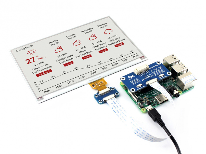
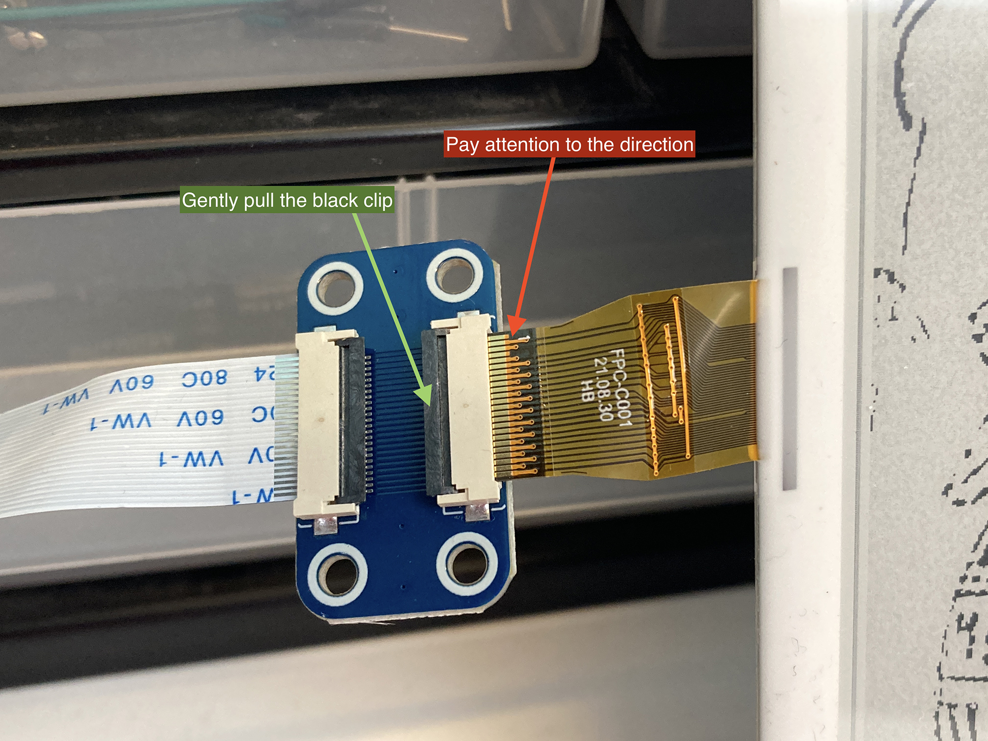
You may need to insert the ribbon cable (the golden one) from the display to the HAT.
- Gently pull up the black clip (green arrow)
- Insert the golden cable (red arrow, pay attention to the direction)
- Press down the black clip to secure it.
Setting Up the Pi
Enable SPI in pi
- Input this command
sudo raspi-configin the Terminal. - Navigate to Interface Options → SPI → Enable
- Reboot the pi by
sudo reboot
Install Python Library
sudo apt-get update
sudo apt-get install python3-pip
sudo apt-get install python3-pil
sudo apt-get install python3-numpy
sudo pip3 install RPi.GPIO
sudo pip3 install spidev
Download Python Example code from Github
git clone https://github.com/waveshare/e-Paper.git
Go to the Directory (folder) where the example codes are located
cd e-Paper/RaspberryPi_JetsonNano/python/examples/
Run the Python Code
You can either run the code from the Terminal or use a Python-based software such as Visual Studio or Thonny. In Terminal:
python3 epd_7in5_V2_test.py
The display should now be blinking and have some demos displayed.
Something more
The below code is to draw a rectangle with random size and location on the display.
#!/usr/bin/python
# -*- coding:utf-8 -*-
import sys
import os
libdir = os.path.join(os.path.dirname(os.path.dirname(os.path.realpath(__file__))), 'lib')
if os.path.exists(libdir):
sys.path.append(libdir)
import logging
import random
from waveshare_epd import epd7in5_V2
import time
from PIL import Image,ImageDraw,ImageFont
import traceback
logging.basicConfig(level=logging.DEBUG)
try:
logging.info("epd7in5_V2 Demo")
epd = epd7in5_V2.EPD()
logging.info("init and Clear")
epd.init_fast()
epd.Clear()
#print(f"Display Width: {epd.width}, Display height: {epd.height}")
# Display Width: 800, Display height: 480
# Create a blank image
Himage = Image.new('1', (epd.width, epd.height), 255) #255: white, clear the frame
draw = ImageDraw.Draw(Himage)
#Drawing function Argyments:
# draw.rectangle((x1, y1, x2, y2), outline=0, fill=None)
# draw.arc((x1, y1, x2, y2),startAngle, endAngle, fill=0), (x1, y1, x2, y2) bounding box of the ellipse that the arc is part of
# draw.chord((x1, y1, x2, y2), startAngle, endAngle, outline=0, fill=None), different to arc as it will close the shape and allow fill colour
# draw.line((x1, y1, x2, y2), fill=0, width=1)
while True:
#Generate a random pattern
draw.rectangle((random.randint(10,epd.width-10), random.randint(10,epd.height-10), random.randint(10,epd.width-10), random.randint(10,epd.height-10)), outline=0)
#Display the generated image
epd.display(epd.getbuffer(Himage))
#Hold the frame for 2 seconds
time.sleep(2)
# logging.info("Goto Sleep...")
# epd.sleep()
except IOError as e:
logging.info(e)
except KeyboardInterrupt:
logging.info("ctrl + c:")
epd7in5_V2.epdconfig.module_exit(cleanup=True)
exit()
How to Display Animation on Waveshare E-Paper Display
How to use Waveshare E-Paper Display?
Please follow the previous tutorial for setting up the basic. This tutorial assumes you already have an animation ready to use.
What type of animation will be suitable to display on E-Paper
- Black and White, as the display we have in stock is Black and White only
- Low framerate animation, such as hand-drawn animation, as the display is not refreshing very fast.
- Short animation, depends on the Pi you use, Pi 3 may not be powerful enough to drive and store long animation.
File Preparation - Adobe Premiere Pro
- Resize the resolution to fit the display - 800x480 pixels
- Lower the framerate to 10 or 12 fps
- Export the video to jpg sequences from Premier and save them in a folder called ‘animation’
- Rename all jpg to
1.jpg to #.jpgusing Terminal, if they are not alreadycd /path/to/your/folder a=1 for file in Sequence*.jpg; do mv "$file" "$a.jpg" ((a++)) done - Now you can transfer the folder to the Raspberry Pi, you can use a USB stick or via SSH. Place the folder
animationinside the foldere-Paper.
File Preparation - Raspberry Pi
We will need to convert jpg to bmp in Pi using ffmpeg.
- Install ffmpeg,
sudo apt install ffmpeg -y - Make sure you are at the
/animationdirectory - Start conversion,
for f in *.jpg; do ffmpeg -i "$f" "${f%.jpg}.bmp"; done - Remove old jpg files,
rm *.jpg - Now all images in the animation folder should look like
1.bmp to #.bmp
Code
The below code will display the animation from frame 1 to the end frame.
!/usr/bin/python
# -*- coding:utf-8 -*-
# Display Width: 800, Display height: 480
import sys
import os
libdir = os.path.join(os.path.dirname(os.path.dirname(os.path.realpath(__file__))), 'lib')
if os.path.exists(libdir):
sys.path.append(libdir)
import logging
import random
from waveshare_epd import epd7in5_V2
import time
from PIL import Image,ImageDraw,ImageFont
import traceback
logging.basicConfig(level=logging.DEBUG)
try:
logging.info("epd7in5_V2 Animation")
epd = epd7in5_V2.EPD()
logging.info("init and Clear")
epd.init_fast()
epd.Clear()
animation_dir = os.path.join(os.path.dirname(os.path.dirname(os.path.realpath(__file__))), 'animation')
image_files = sorted(
[f for f in os.listdir(animation_dir) if f.endswith('.bmp')],
key=lambda x: int(os.path.splitext(x)[0]))
if not image_files:
logging.info(e)
epd.sleep()
exit()
logging.info("switch to partial refresh")
epd.init_part()
while True:
for image_file in image_files:
image_path = os.path.join(animation_dir, image_file)
logging.info(f"Displaying: {image_file}")
Himage = Image.open(image_path).convert('1')
epd.display_Partial(epd.getbuffer(Himage), 0, 0, epd.width, epd.height)
# time.sleep(0.1)
except IOError as e:
logging.info(e)
except KeyboardInterrupt:
logging.info("ctrl + c:")
epd7in5_V2.epdconfig.module_exit(cleanup=True)
exit()
How to send files to Raspberry Pi using SSH
What is SSH?
SSH stands for Secure Shell — it’s a network protocol that lets you securely log in to and control another computer remotely, usually over the internet or your local network.
Think of it as opening a remote terminal window on your Raspberry Pi from your laptop or another device.
What You Can Do with SSH:
- Run terminal commands on your Pi from another machine
- Transfer files (using scp, rsync, or SFTP)
- Install software, run Python scripts, update your system
- Control a headless Raspberry Pi (one without monitor/keyboard)
Enable SSH on Raspberry Pi
Option 1: Using Raspberry Pi OS with Desktop
- Go to Preferences → Raspberry Pi Configuration
- Under the Interfaces tab, enable SSH
- Reboot afterwards,
sudo reboot
Option 2: If You’re Using Pi Headless
- Put a file named ssh (with no extension) into the boot partition of the SD card
- When the Pi boots, SSH will be enabled
Find Pi's IP address
- In Terminal,
hostname -I - You will see something that looks like this:
192.168.1.42, this is your pi's IP address
File Transfer
1. From Your Computer → Raspberry Pi
scp /path/to/local/file pi@<raspberry_pi_ip>:/home/pi/
2. To Send a Whole Folder
scp -r /path/to/local/folder pi@<raspberry_pi_ip>:/home/pi/
3. From Raspberry Pi → Your Computer
scp pi@<raspberry_pi_ip>:/home/pi/somefile.txt /local/path/
Tips
- The default username is usually
pi - If SSH asks you to confirm the connection the first time, type
yes - If your Pi is using a custom SSH port (e.g. 2222), add
-P 2222
How to use Raspberry Pi Camera Module 3
What is Raspberry Pi Camera Module 3?
This tutorial will walk you through setting up and using the Raspberry Pi Camera Module 3 Noir on a Raspberry Pi 5, but other Pi like Pi 3 and Pi 4 will work as well.
Camera Module 3 — Key Features
| Feature | Description |
|---|---|
| Sensor | Sony IMX708 |
| Resolution | 12MP (4608 × 2592) |
| Autofocus | ✅ Yes (PDAF or EDOF depending on model) |
| HDR | ✅ Available on certain models |
| FoV Variants | Standard & Wide-angle |
| IR Version | Available (NoIR version) |
| Interface | CSI-2 via 22-pin MIPI ribbon cable |
| OS Support | Raspberry Pi OS Bookworm or later |
Requirements
Hardware
- Raspberry Pi (Pi 3 or later)
- Camera Module 3 (ensure it’s a v3 model)
- Camera ribbon cable (22-pin), Pi5 will need a 22pin to 15pin ribbon cable
- Power supply & HDMI or SSH access
Software
- Raspberry Pi OS Bookworm (64-bit recommended)
- Camera support via libcamera stack
- picamera2 Python library
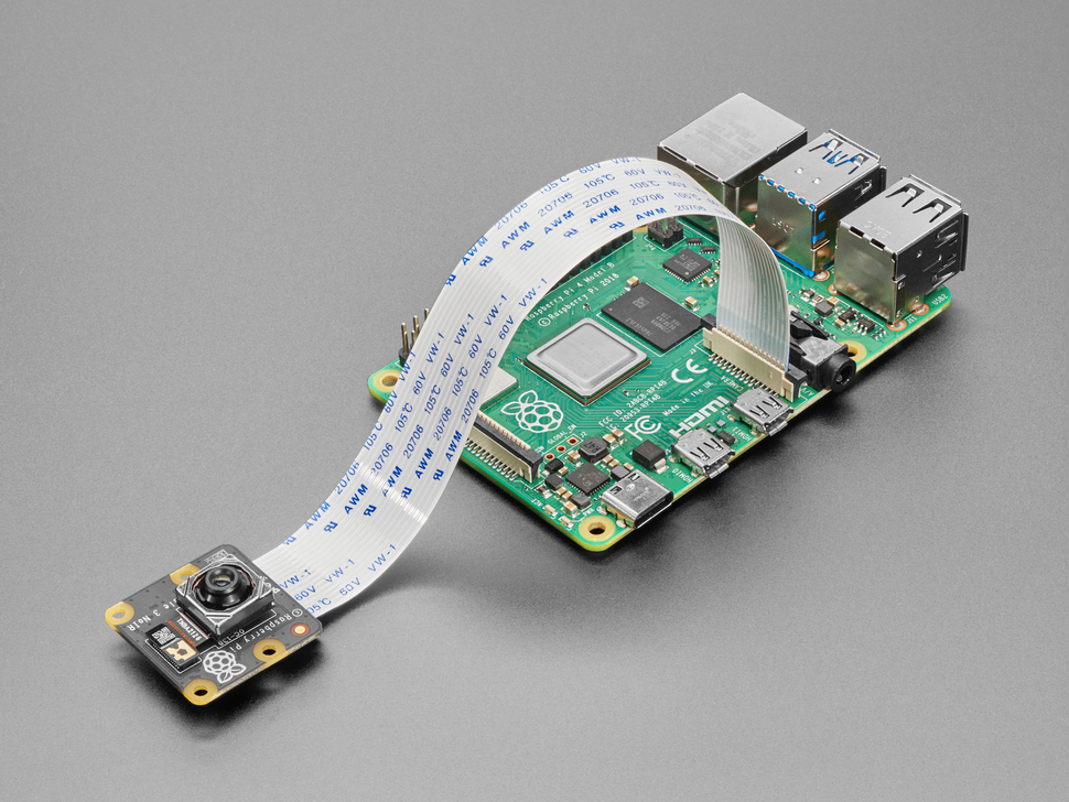
Physical Connection
- Power off your Pi.
- Locate the CSI camera port on the board (next to the HDMI ports).
- Gently lift the connector latch.
- Insert the ribbon cable on the Pi: the blue tab faces the Ethernet port, metal pins toward HDMI.
- Insert the ribbon cable on the camera: blue side usually faces away from the camera sensor.
- Close the latch and ensure it’s snug.
- Power on the Pi.
Enable I2C communication
-
sudo raspi-config - Interface Options -> I2C -> Enable
-
sudo reboot
Update OS & Install Required Packages
sudo apt update && sudo apt upgrade -y
sudo apt install -y libcamera-apps python3-picamera2 python3-opencv
Test Camera via Terminal
- Basic Camera Preview (HDMI required):
libcamera-hello - Take a Photo:
libcamera-jpeg -o test.jpg - Record a Video (10 seconds):
libcamera-vid -t 10000 -o test.h264
Testing Code
Python Code Using picamera2
This code will pop a new window of live preview with autofocus.
from picamera2 import Picamera2
from libcamera import controls
import time
picam2 = Picamera2()
picam2.start(show_preview=True)
# Enable continuous autofocus
picam2.set_controls({"AfMode": controls.AfModeEnum.Continuous})
print("Camera feed started. Press Ctrl+C to stop.")
try:
while True:
time.sleep(1)
except KeyboardInterrupt:
picam2.stop()
print("Camera stopped.")
Face Detection Example with OpenCV
- Download the Haar Cascade XML and saved it in a folder called
haarcascades.wget -P ~ https://github.com/opencv/opencv/raw/master/data/haarcascades/haarcascade_frontalface_default.xml
import cv2
import numpy as np
from picamera2 import Picamera2
from libcamera import controls
import warnings
# Suppress the specific warning from OpenCV
warnings.filterwarnings("ignore", category=UserWarning, module="cv2")
# Initialize the Picamera2 instance
picam2 = Picamera2()
# Start the camera (no preview for better performance during processing)
picam2.start()
# Set autofocus to continuous mode
picam2.set_controls({"AfMode": controls.AfModeEnum.Continuous})
# Manually specify the path to the Haar Cascade file
face_cascade = cv2.CascadeClassifier('/home/pi/haarcascades/haarcascade_frontalface_default.xml') # Adjust this path if necessary
# Check if the cascade classifier is loaded properly
if face_cascade.empty():
print("Error loading Haar Cascade classifier. Make sure the path is correct.")
exit()
# Start capturing frames and detecting faces
while True:
# Capture a frame from the camera
frame = picam2.capture_array()
# Check if the frame was captured successfully
if frame is None:
print("Failed to capture frame.")
break
# Convert the image to grayscale (required for Haar Cascade)
gray = cv2.cvtColor(frame, cv2.COLOR_BGR2GRAY)
# Detect faces in the image
faces = face_cascade.detectMultiScale(gray, 1.1, 4)
# Loop through the faces and draw rectangles around them
for (x, y, w, h) in faces:
# Draw a thin rectangle (face bounding box) around the detected face
cv2.rectangle(frame, (x, y), (x + w, y + h), (0, 255, 0), 2)
# Show the frame with the face(s) detected
# Convert the frame to a simpler BGR format or grayscale
frame = cv2.cvtColor(frame, cv2.COLOR_BGR2RGB) # Convert to RGB
cv2.imshow("Face Detection", frame)
# If the 'q' key is pressed, exit the loop
if cv2.waitKey(1) & 0xFF == ord('q'):
break
# Clean up
picam2.stop() # Stop the camera
cv2.destroyAllWindows() # Close all OpenCV windows
How to do Basic Commands in Terminal
Raspberry Pi Terminal Command Cheat Sheet
| Command | Description |
|---|---|
ls |
List all files and directories in the current folder |
cd foldername |
Change to a specific directory |
cd .. |
Go up one directory |
mkdir myfolder |
Create a new directory called myfolder |
rm myfile.txt |
Delete a file called myfile.txt |
rm -r myfolder |
Delete a folder and its contents |
cp file1.txt file2.txt |
Copy file1.txt to file2.txt |
mv file.txt folder/ |
Move file.txt into the folder |
nano script.py |
Edit a Python script using the built-in text editor |
python3 script.py |
Run a Python 3 script |
chmod +x script.sh |
Make a shell script executable |
./script.sh |
Run an executable shell script |
sudo shutdown now |
Shutdown the Raspberry Pi immediately |
sudo reboot |
Reboot the Raspberry Pi |
clear |
Clear the terminal screen |
sudo apt update |
Update the list of available packages |
sudo apt upgrade |
Upgrade installed packages to the latest version |
sudo apt install package-name |
Install a software package (e.g., python3-opencv) |
git clone https://github.com/user/repo.git |
Download a GitHub repository to your local Pi |
Pi War 2024 Log
Documentation of Pi War 2024
Pi Wars is an international, challenge-based robotics competition in which teams build Raspberry Pi-controlled robots and then compete in various non-destructive challenges to earn points.

Planning
We planned to build a four-wheel robot car which is driven by two TT motors and Raspberry Pi Pico W. We will use a second Raspberry Pi Pico W and two joysticks for the remote controller. The car and the controller will communicate via WiFi.

Circuit
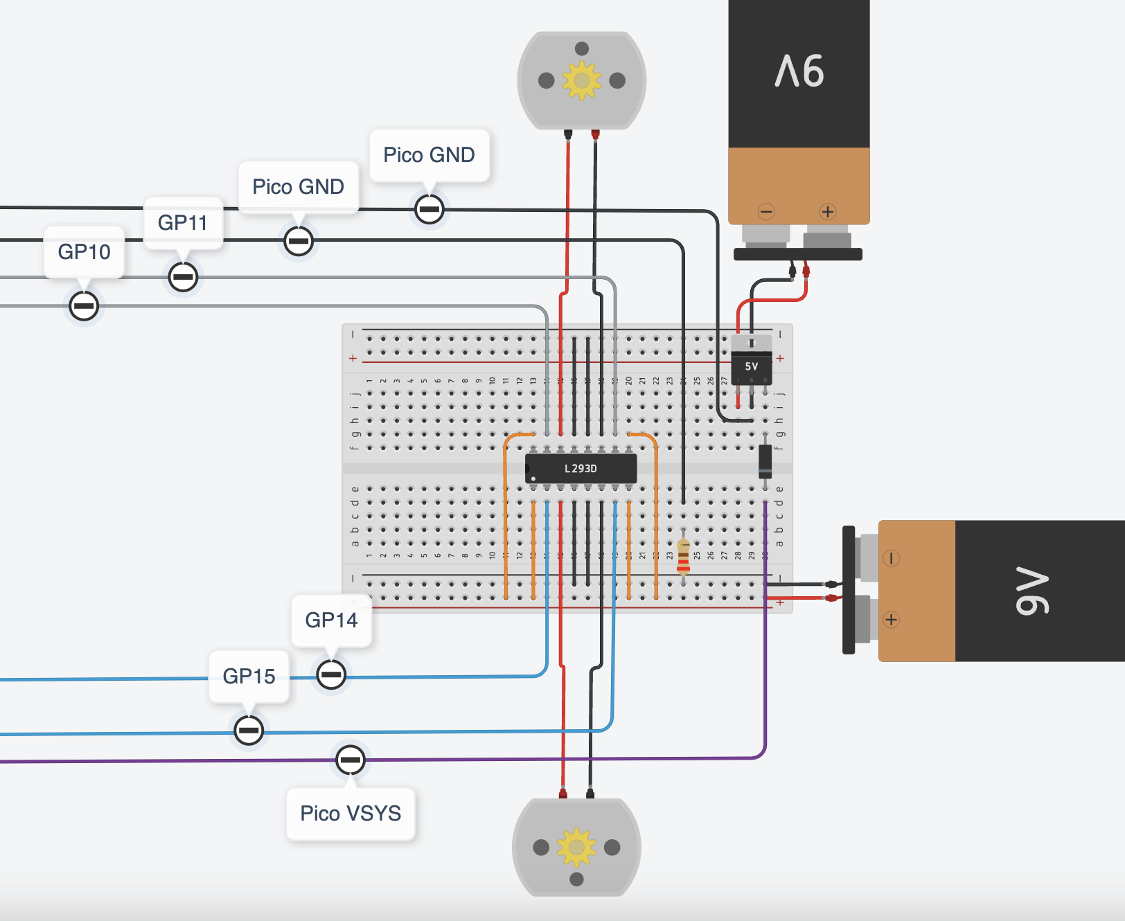
Car Circuit
We used a 5V regulator LM7805 to regulate 9V from the 9V battery to 5V to power up the Raspberry Pico via the VSYS and GND pins. A diode between VSYS and 5V output to present backfeeding. More about powering Pico.
We used a second 9V battery to power up two TT motors, both power sources share the same ground.
We used an L293D IC for controlling two motors. GPIO10 and GPIO11 pins control the directions of the left motor and GPIO14 and GPIO15 pins control the directions of the right motor. More about L293D IC.
Controller Circuit
We use the same 5V regulator LM7805 to regulate the power supply for Raspberry Pico, and connect two joysticks's data pins with pins GPIO26 and GPIO27. One joystick controls left and right, and the other controls forward and backwards.
Problems with batteries
This is a remote-controlled robot car so it needs to be wireless and must use battery as its power supply. However, the battery is not a stable power supply which cannot supply a constant stable 9V to both the motors and Pico. Even when the battery is not completely dry, it may become insufficient to turn on the Pico when the voltage drops below a certain point. The same problem goes for the motors but is less fatal, as the motors can still run, just slower.
This time, we just decided to change batteries more often, but it is not environmentally friendly or efficient. We will look into power banks with a low-current charging mode.
Python Code
All codes can be found on our Github page.
Testing two motors
import time
from machine import Pin
motor1a = Pin(14, Pin.OUT)
motor1b = Pin(15, Pin.OUT)
motor2a = Pin(10, Pin.OUT)
motor2b = Pin(11, Pin.OUT)
print("Hello.")
def right_forward():
motor1a.value(0)
motor1b.value(0)
motor2a.value(0)
motor2b.value(1)
def left_forward():
motor2a.value(0)
motor2b.value(0)
motor1a.value(1)
motor1b.value(0)
def right_backward():
motor1a.value(0)
motor1b.value(0)
motor2a.value(1)
motor2b.value(0)
def left_backward():
motor2a.value(0)
motor2b.value(0)
motor1a.value(0)
motor1b.value(1)
def forward():
motor1a.value(1)
motor1b.value(0)
motor2a.value(0)
motor2b.value(1)
def backward():
motor1a.value(0)
motor1b.value(1)
motor2a.value(1)
motor2b.value(0)
def stop():
motor1a.value(0)
motor1b.value(0)
motor2a.value(0)
motor2b.value(0)
Testing two joysticks
import time
from machine import ADC, Pin
HIGH = 35000
LOW = 30000
def is_still(val):
return val > LOW and val < HIGH
def increase(val):
return val > HIGH
def decrease(val):
return val < LOW
joystick_y = ADC(Pin(26))
joystick_x = ADC(Pin(27))
STOP = 1
STRAIGHT_FORWARD = 2
RIGHT_FORWARD = 3
LEFT_FORWARD = 4
RIGHT_BACKWARD = 5
LEFT_BACKWARD = 6
STRAIGHT_BACKWARD = 7
while True:
x_val = joystick_x.read_u16()
y_val = joystick_y.read_u16()
x_still = is_still(x_val)
y_still = is_still(y_val)
x_increase = increase(x_val)
y_increase = increase(y_val)
x_decrease = decrease(x_val)
y_decrease = decrease(y_val)
if x_still and y_still:
print(STOP)
if y_increase and x_still:
print(STRAIGHT_FORWARD)
if y_decrease and x_still:
print(STRAIGHT_BACKWARD)
if y_increase and x_increase:
print(LEFT_FORWARD)
if y_increase and x_decrease:
print(RIGHT_FORWARD)
if y_decrease and x_increase:
print(LEFT_BACKWARD)
if y_decrease and x_decrease:
print(RIGHT_BACKWARD)
time.sleep(0.1)
When using wifi communication, the controller will be the server and the car will be the client.
Testing wifi communication - SERVER
import random
import socket
import time
import network
from machine import ADC, Pin
ssid = "WIFI_NAME"
password = "WIFI_PASSWORD"
wlan = network.WLAN(network.STA_IF)
wlan.active(True)
wlan.connect(ssid, password)
# Wait for connect or fail
max_wait = 10
while max_wait > 0:
if wlan.status() < 0 or wlan.status() >= 3:
break
max_wait -= 1
print("waiting for connection...")
time.sleep(1)
# Handle connection error
if wlan.status() != 3:
raise RuntimeError("network connection failed")
else:
print("connected")
status = wlan.ifconfig()
# print('ip = ' + status[0])
# Open socket
addr = socket.getaddrinfo("0.0.0.0", 80)[0][-1]
s = socket.socket()
s.bind(addr)
s.listen(1)
print("listening on", addr)
# Listen for connections
while True:
try:
cl, addr = s.accept()
request = cl.recv(1024)
print(request)
# No need to unpack request in this example
ran_num = str(random.randint(0, 100))
cl.send(ran_num)
print("Sent: " + ran_num)
cl.close()
except OSError as e:
cl.close()
print("connection closed")
Testing wifi communication - CLIENT
Make sure you change the IP address of your pi, which you can find in the console when you run the above server code.
import random
import socket
import time
import network
from machine import ADC, Pin
ssid = "WIFI_NAME"
password = "WIFI_PASSWORD"
wlan = network.WLAN(network.STA_IF)
wlan.active(True)
wlan.connect(ssid, password)
# Wait for connect or fail
max_wait = 10
while max_wait > 0:
if wlan.status() < 0 or wlan.status() >= 3:
break
max_wait -= 1
print("waiting for connection...")
time.sleep(1)
# Handle connection error
if wlan.status() != 3:
raise RuntimeError("network connection failed")
else:
print("connected")
status = wlan.ifconfig()
# print('ip = ' + status[0])
while True:
ai = socket.getaddrinfo("192.168.1.115", 80) # Address of Web Server
addr = ai[0][-1]
# Create a socket and make a HTTP request
s = socket.socket() # Open socket
s.connect(addr)
s.send(b"Anything") # Send request
ss = str(s.recv(512)) # Store reply
# Print what we received
print(ss)
# Set RGB LED here
s.close() # Close socket
time.sleep(0.2) # wait
Final code for controller - SERVER
import socket
import time
import network
from machine import ADC, Pin
HIGH = 35000
LOW = 30000
def is_still(val):
return val > LOW and val < HIGH
def increase(val):
return val > HIGH
def decrease(val):
return val < LOW
joystick_y = ADC(Pin(26))
joystick_x = ADC(Pin(27))
led = Pin("LED", Pin.OUT)
STOP = 1
STRAIGHT_FORWARD = 2
RIGHT_FORWARD = 3
LEFT_FORWARD = 4
RIGHT_BACKWARD = 5
LEFT_BACKWARD = 6
STRAIGHT_BACKWARD = 7
ssid = "WIFI_NAME"
password = "WIFI_PASSWORD"
wlan = network.WLAN(network.STA_IF)
wlan.active(True)
wlan.connect(ssid, password)
# Wait for connect or fail
max_wait = 10
while max_wait > 0:
if wlan.status() < 0 or wlan.status() >= 3:
break
max_wait -= 1
print("waiting for connection...")
time.sleep(1)
# Handle connection error
if wlan.status() != 3:
raise RuntimeError("network connection failed")
else:
print("connected")
status = wlan.ifconfig()
print('ip = ' + status[0])
led.on()
# Open socket
addr = socket.getaddrinfo("0.0.0.0", 80)[0][-1]
s = socket.socket()
s.bind(addr)
s.listen(1)
print("listening on", addr)
while True:
try:
cl, addr = s.accept()
request = cl.recv(1024)
print("request", request)
# print("loop")
x_val = joystick_x.read_u16()
y_val = joystick_y.read_u16()
x_still = is_still(x_val)
y_still = is_still(y_val)
x_increase = increase(x_val)
y_increase = increase(y_val)
x_decrease = decrease(x_val)
y_decrease = decrease(y_val)
if x_still and y_still:
print(STOP)
cl.send(str(STOP))
if y_increase and x_still:
print(STRAIGHT_FORWARD)
cl.send(str(STRAIGHT_FORWARD))
if y_decrease and x_still:
print(STRAIGHT_BACKWARD)
cl.send(str(STRAIGHT_BACKWARD))
if y_increase and x_increase:
print(LEFT_FORWARD)
cl.send(str(LEFT_FORWARD))
if y_increase and x_decrease:
print(RIGHT_FORWARD)
cl.send(str(RIGHT_FORWARD))
if y_decrease and x_increase:
print(LEFT_BACKWARD)
cl.send(str(LEFT_BACKWARD))
if y_decrease and x_decrease:
print(RIGHT_BACKWARD)
cl.send(str(RIGHT_BACKWARD))
cl.close()
except Exception as e:
print(e)
cl.close()
print("connection closed")
time.sleep(0.1)
Final code for car - CLIENT
import random
import socket
import time
import network
from machine import ADC, Pin
motor1a = Pin(14, Pin.OUT)
motor1b = Pin(15, Pin.OUT)
motor2a = Pin(10, Pin.OUT)
motor2b = Pin(11, Pin.OUT)
led = Pin("LED", Pin.OUT)
ssid = "WIFI_NAME"
password = "WIFI_PASSWORD"
wlan = network.WLAN(network.STA_IF)
wlan.active(True)
wlan.connect(ssid, password)
# Wait for connect or fail
max_wait = 10
while max_wait > 0:
if wlan.status() < 0 or wlan.status() >= 3:
break
max_wait -= 1
print("waiting for connection...")
time.sleep(1)
# Handle connection error
if wlan.status() != 3:
raise RuntimeError("network connection failed")
else:
print("connected")
status = wlan.ifconfig()
print('ip = ' + status[0])
led.on()
def right_forward():
motor1a.value(0)
motor1b.value(0)
motor2a.value(0)
motor2b.value(1)
def left_forward():
motor2a.value(0)
motor2b.value(0)
motor1a.value(1)
motor1b.value(0)
def right_backward():
motor1a.value(0)
motor1b.value(0)
motor2a.value(1)
motor2b.value(0)
def left_backward():
motor2a.value(0)
motor2b.value(0)
motor1a.value(0)
motor1b.value(1)
def forward():
motor1a.value(1)
motor1b.value(0)
motor2a.value(0)
motor2b.value(1)
def backward():
motor1a.value(0)
motor1b.value(1)
motor2a.value(1)
motor2b.value(0)
def stop():
motor1a.value(0)
motor1b.value(0)
motor2a.value(0)
motor2b.value(0)
commands = {
"1": stop,
"2": forward,
"3": right_forward,
"4": left_forward,
"5": right_backward,
"6": left_backward,
"7": backward,
}
while True:
ai = socket.getaddrinfo("192.168.0.100", 80) # Address of Web Server
addr = ai[0][-1]
# Create a socket and make a HTTP request
s = socket.socket() # Open socket
s.connect(addr)
s.send(b"Anything") # Send request
ss = s.recv(512).decode() # Store reply
# Print what we received
try:
commands[ss]()
except KeyError:
commands["1"]()
# Set RGB LED here
s.close() # Close socket
time.sleep(0.2) # wait
Router Setting
In general, if both the server pico and the client pico are connected to the same wifi network, they can communicate. However, most routers provide a dynamic IP address which may change every time, based on the number of devices connected and which device is connected to the network first. We only used the router for the controller and the car in the beginning, and we started to experience problems when there were other devices connected to our router.
Therefore, we need to reserve IP addresses for the controller and the car, to make sure they are listening to the right address. This process may be different based on what router you are using.
You may see something similar like this:

Car Design
The car is Princess Peach-inspired, so very pink. We laser-cut serval layers to form the main body of the car.
Problems with back wheels
We have four identical wheels. However, the rubber surface of the back wheels has created too much friction which the front wheels are not powerful enough to pull. In the end, we needed to remove the rubber bit of the back wheels.
Controller Design
Continue with the Princess Peach theme, the controller is a heart-shaped box with holes for the on-off button and two joysticks.


Final Controller!


Testing!
Competition Day Snaps
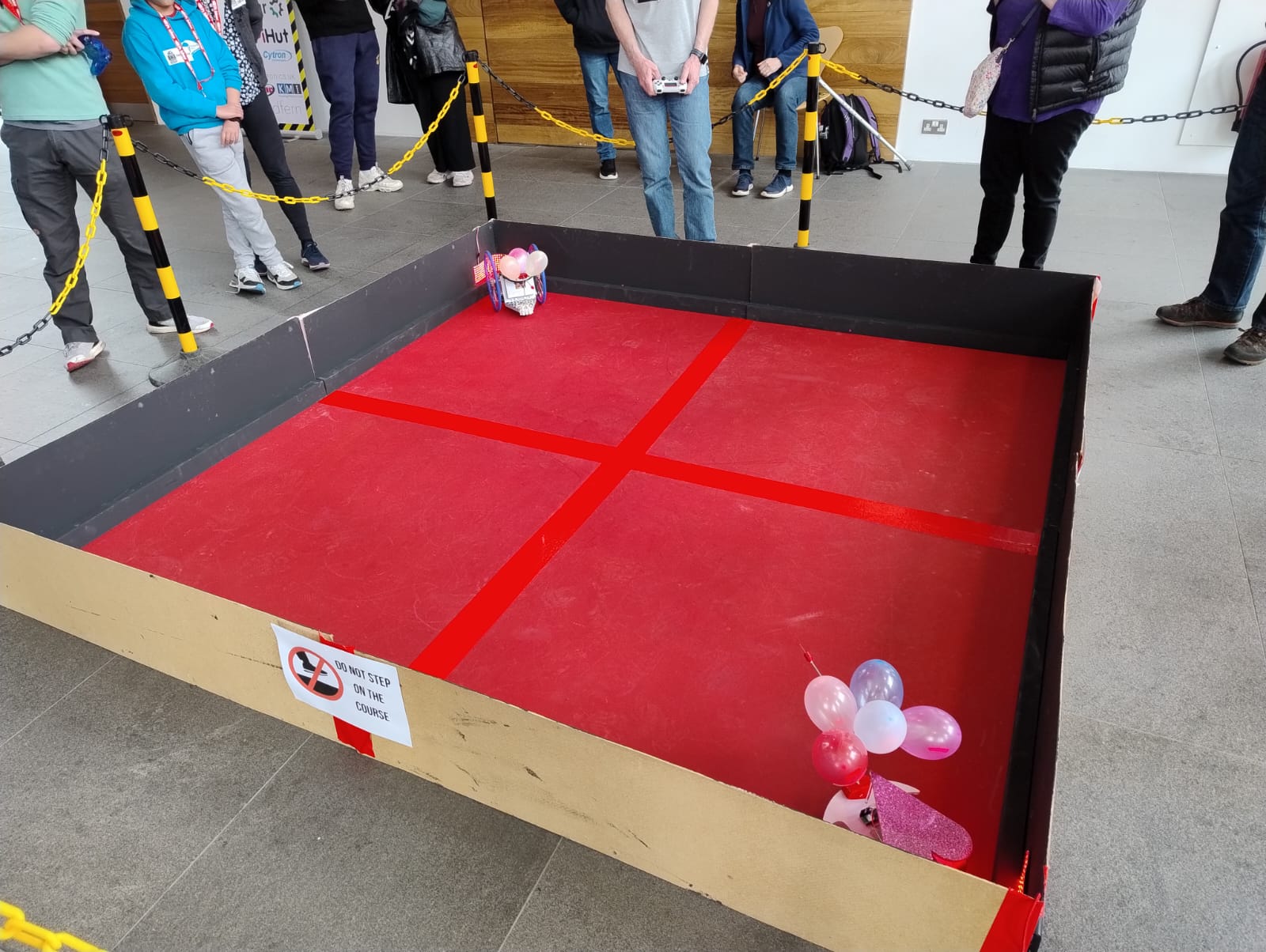
Challenge 1 - Pi Noon: The Hindenburg Disaster
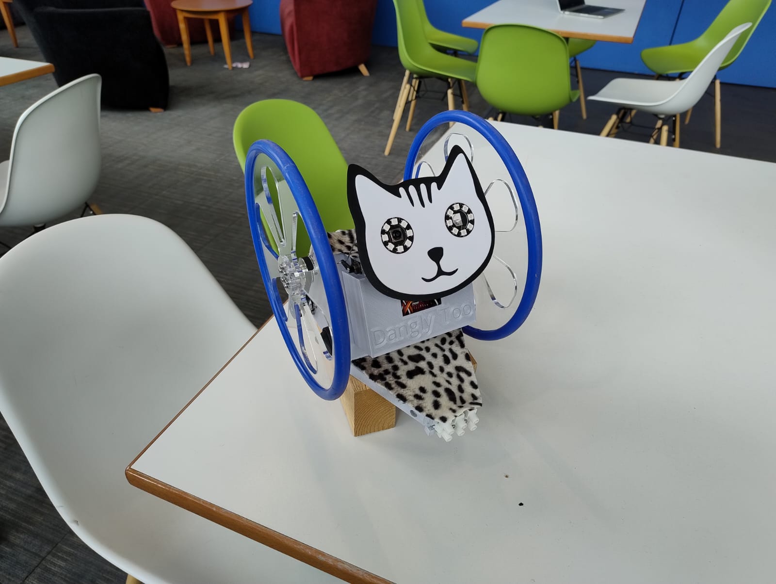
We need to poke the balloons on our opponent. This is our opponent, Dangly TOO!
Challenge 2 - Eco Disaster
We need to put the green barrels in the blue square and the red barrels in the yellow square. There were some impressive robots doing it autonomously!

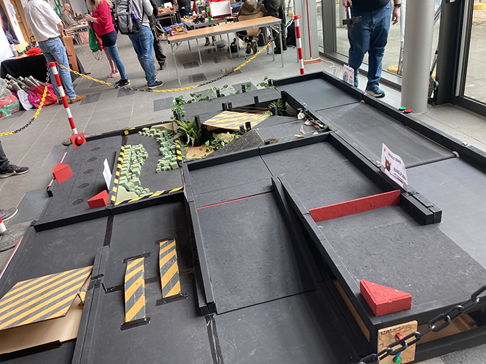
Challenge 3 - Minesweeper
We need to go to the red lightbox as fast as we can.

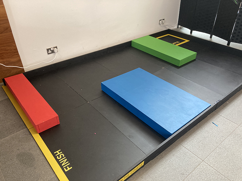
Challenge 4 - Escape Route
We need to escape the maze without looking at it.
Challenge 5 - The Zombie Apocalypse
Challenge 6 - The Temple of Doom
This is the hardest and the most unexpected challenge of all. Unfortunately, Edwina is not built for this, so we didn't finish the course.