Touchdesigner
- Basics of Touchdesigner
- Installing the software
- Intro to Touchdesigner
- A circle following the mouse
- Switch Operator
- Other resources
- Interactive Media
Basics of Touchdesigner
Installing the software
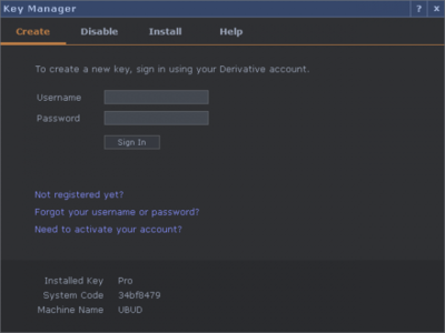
If you are using the Macbooks available for LCC's library:
If you are using one of the MacBooks from the library you must use UAL's Self Service app. Here search for "Derivative Touch Designer" and install. Now register for an account at https://derivative.ca. Look for the header "My Licenses", on the right, from here "Create Key" by typing in your system code and machine name, this will come up in a window on Touchdesigner when you first try launching it.
If you are using your own device:
Before installing Touchdesigner...
Make sure to update your system, Touchdesigner is constantly being updated and might require the latest version of your system.
Download the software
Download the right release for your system: https://derivative.ca/download. Touchdesigner is free but this release comes with a couple of limitations, but nothing that would stop you from working on your project. On the same page register for an account and look for the header "My Licenses", on the right. From here "Create Key" by typing in your system code and machine name, this will come up in a window on Touchdesigner when you first try launching it.
Intro to Touchdesigner
About the software
Touchdesigner is a programming software popular amongst all kinds of creatives. Within the Creative Technology Lab we support students in developing interactive projects, often combined with physical computing and projection mapping.
Touchdesigner is a node-based software, a type of visual programming language. This means that for the most part we won't be dealing with tradition coding, instead we will be using nodes called Operators. These are ready-made "blocks of code", each performing different functions. Linking nodes together allows us to manipulate data and program our network. A bit like using layers in Photoshop, every new node you add alters the previous one, however in Touchdesigner data flows left to right.
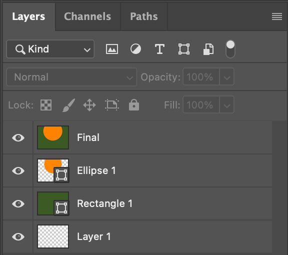
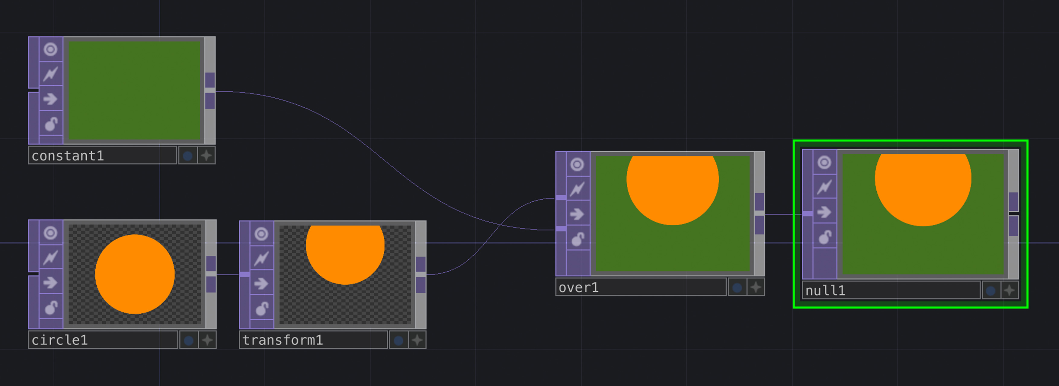
Layers in Photoshop. Nodes linked to create a network in Touchdesigner.
Navigating the Interface
Moving around in TouchDesigner can sometimes be confusing, especially for trackpad users. Press down on the trackpad to navigate your network or use two fingers to zoom in and out—particularly useful for moving between layers of your project. For mouse users, left-click to move around and use the mouse wheel to zoom in and out. In both cases, double-clicking will open the OP Create Dialog, while a right-click will reveal more options.
Operators
A library of all Operators is available by double-clicking anywhere on the background of Touchdesigner. To delete an operator, simply select it then hit the delete key on your keyboard. Operators are grouped into families, each marked with a different heading and color.
TOPS
Texture Operators, also known as TOPs, are all about handling images and videos. They help you modify, combine, and create graphics in real-time.
CHOPS
Channel Operators, also known as CHOPs, work with one or more channels of data. Informations from signals, motion, audio, etc. can be altered and used to control other operators, often TOPs, to perform various animation techniques.
DAT
Data Operators, or DATs, help manage scripts and data tables for communication between different devices or systems. They're really handy for connecting Touchdesigner with external devices like Arduino.
Components
Components are operators containing their own network. The Palette, ![]() located in the top-left corner of TouchDesigner's interface, is a list of all components, each grouped by category. 'Mapping' is just one of these categories, this being particularly useful for projection mapping.
located in the top-left corner of TouchDesigner's interface, is a list of all components, each grouped by category. 'Mapping' is just one of these categories, this being particularly useful for projection mapping.
Parameters Window
Every operator comes with a set of parameters that you can edit to alter its default values. Select your node and press "P" on your keyboard to access or hide the parameters window.
This window offers various functions, each grouped by sub-category. "Common" is a sub-category that applies to all operators; In TOPs it is often used to change the resolution of our visual content. For example, if your webcam's resolution is 1920x1080, the VideoDeviceIn TOP may display a warning: "Resolution limited to a max of 1280x1280 with Non-Commercial key," referring to the maximum resolution available in the free version of TouchDesigner. To address this, you can adjust the resolution in the "Common" category by changing the OUTPUT RESOLUTION to Custom Resolution from the drop-down menu and selecting the desired RESOLUTION by clicking this arrow ![]() . A resolution of 1280x720 is usually a good fit.
. A resolution of 1280x720 is usually a good fit.
Another feature in the parameters window that's common to all operators is the "Help" button ![]() , which launches the Operator's Wiki help page in a new browser window, ie: https://docs.derivative.ca/index.php?title=Video_Device_In_TOP.
, which launches the Operator's Wiki help page in a new browser window, ie: https://docs.derivative.ca/index.php?title=Video_Device_In_TOP.
A circle following the mouse
If you're looking to create interactive projects in Touchdesigner this exercise is a great first step. We will cover some of the most important concepts such as gaining data from external sensors and using it to manipulate visuals.
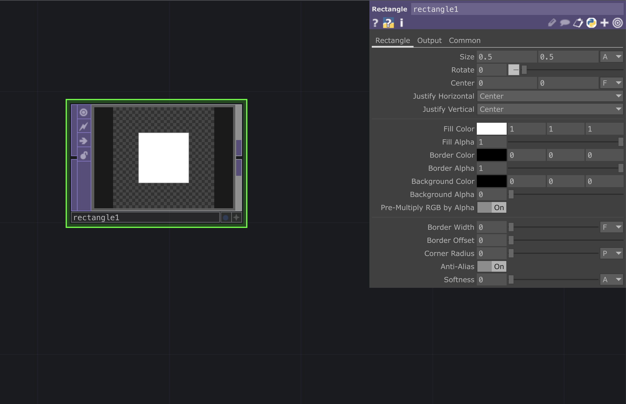
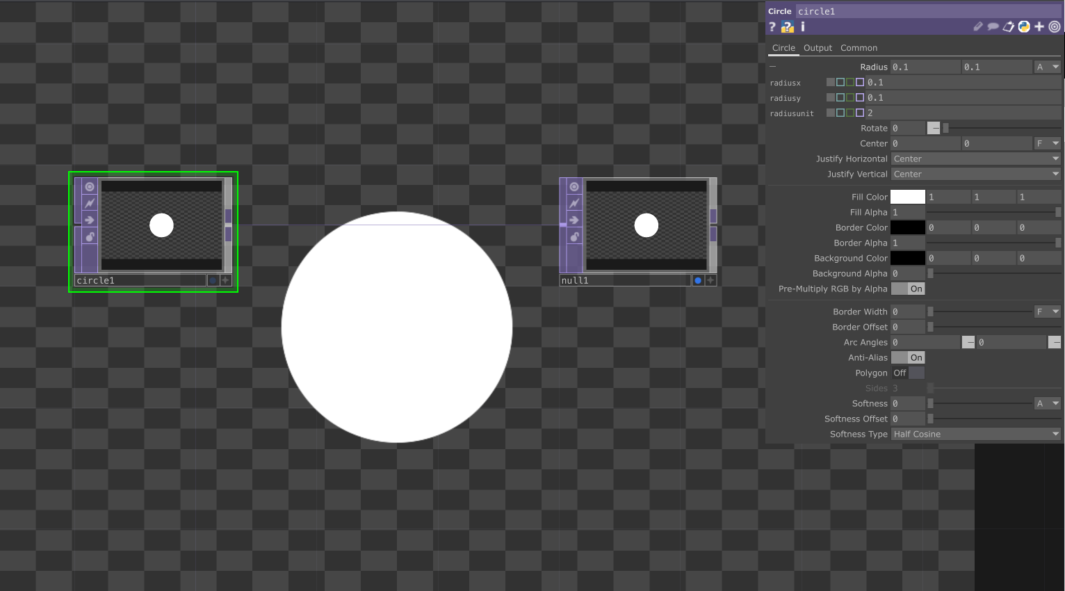
To begin with add a Circle Top and connect it to a Null TOP, then click on the null's Display button - this will help you better monitor any alterations. In the parameters window, we can change the width(x) and height(y) of our circle by clicking on Radius and editing these sizes. You can improve your visual's Resolution by changing it to 1280x720.
Add a Transform TOP after the circle and play around with the Translate parameters to make your circle move along the x and y axis within the canvas' cartesian plane. Take note of your canvas' extremities, ie.: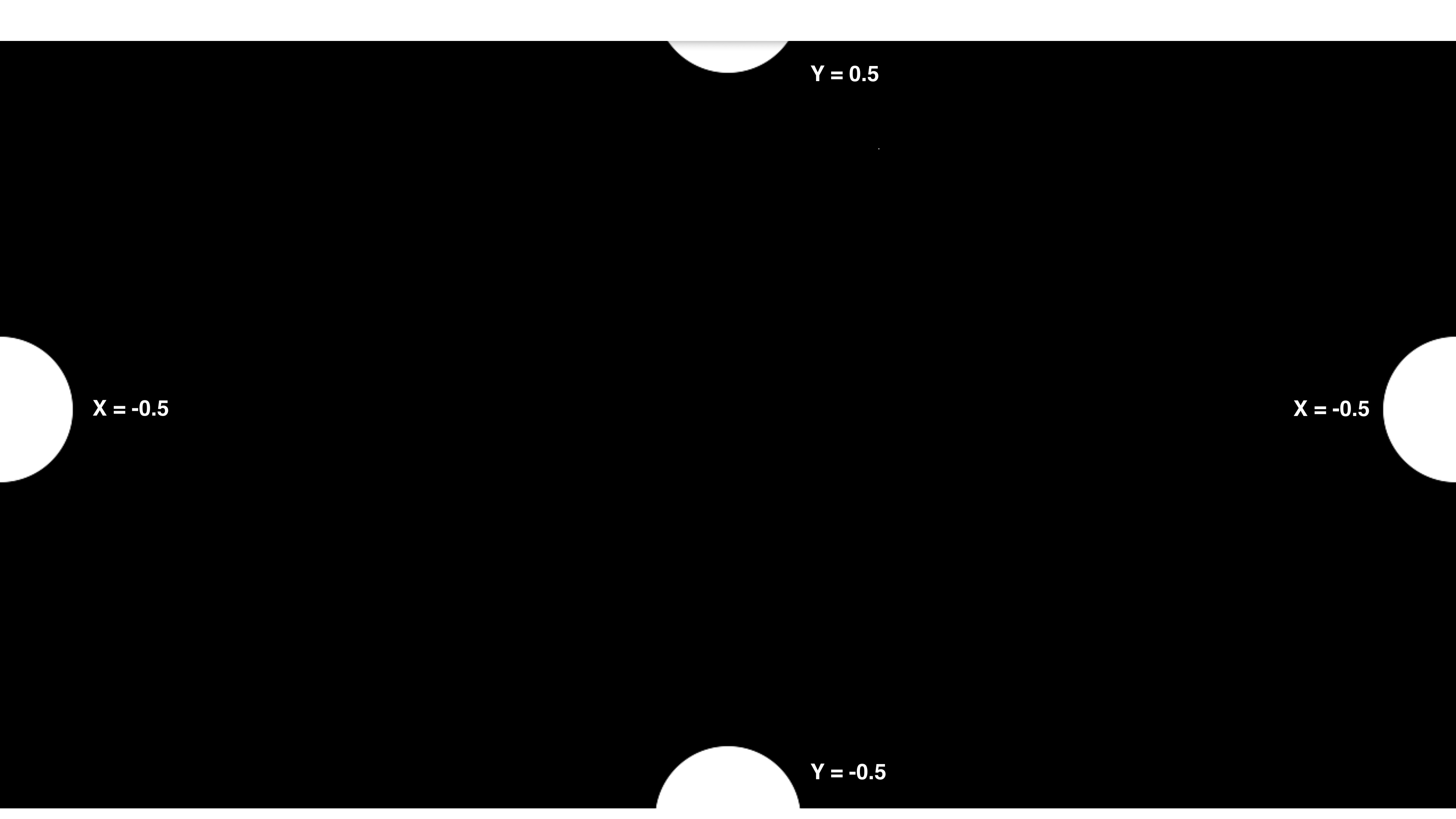
Our aim for this tutorial is to get a circle to follow our mouse, so let's add a MouseIn CHOP. As you move your mouse around the screen you should notice the tx and ty data retained by this operator fluctuate. We'll use these as points of reference for our mouse to follow: Click on the Viewer Active button ![]() to activate the operator, we can now link these channels to the x and y parameters in the Translate TOP. Select the operator and drag and drop the channels from the MouseIn CHOP in the Translate TOP's parameters window, click on CHOP Reference and you should now see the parameter updating in real-time.
to activate the operator, we can now link these channels to the x and y parameters in the Translate TOP. Select the operator and drag and drop the channels from the MouseIn CHOP in the Translate TOP's parameters window, click on CHOP Reference and you should now see the parameter updating in real-time.
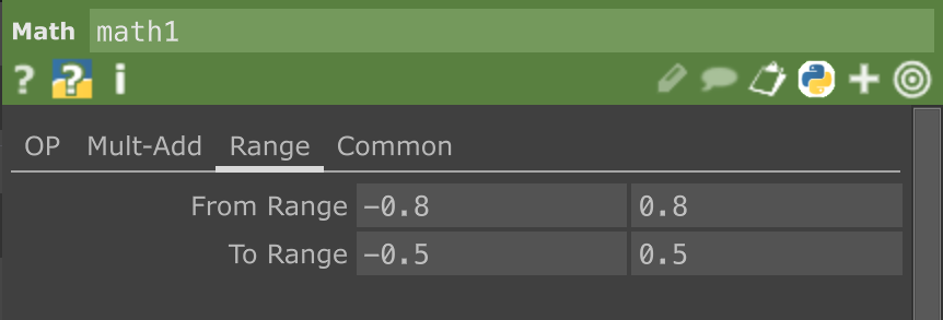
The circle is now moving and following your mouse, however you might notice that on the x-axis this may seem slightly off. We can remap our mouse values to match those of our canvas by adding a Select CHOP to our MouseIn CHOP, and in the parameters window select "tx" for the Channel Names; This allows us to only remap the tx values. Add a Math CHOP and in the sub-category math "Range" you will see two rows:
From Range indicates the original set of values between which x fluctuates. ie. MouseIn CHOP's original x values fluctuate between approximately -0.8 and 0.8 .
To Range indicates the new set of values between we want x to fluctuates. We have previously established that my circle x-axis extremities are between -0.5 and 0.5.
Therefore your Math CHOP should now look like this:
Replace the previous reference with this new set of values by activating ![]() the Math CHOP operator, then drag and drop the channel into the x parameter in Translate TOP.
the Math CHOP operator, then drag and drop the channel into the x parameter in Translate TOP.
The circle should now be following your mouse! This same workflow can be used in other scenarios, with different external inputs such as a webcam or a tracking device, to create live and interactive content.
Switch Operator
A simple yet effective method used in interactive projections consist of alternating between two or more visuals. This could be the result of pressing a button or entering an area that's being tracked with a webcam, etc,.
In this brief tutorial we will look at the Switch TOP, a very useful operator for interactive projects. It is easy to use: Link two MovieDeviceIn TOPs to a Switch TOP and end your network with a Null TOP - activate the operator's display viewer to better monitor any alterations  .
.
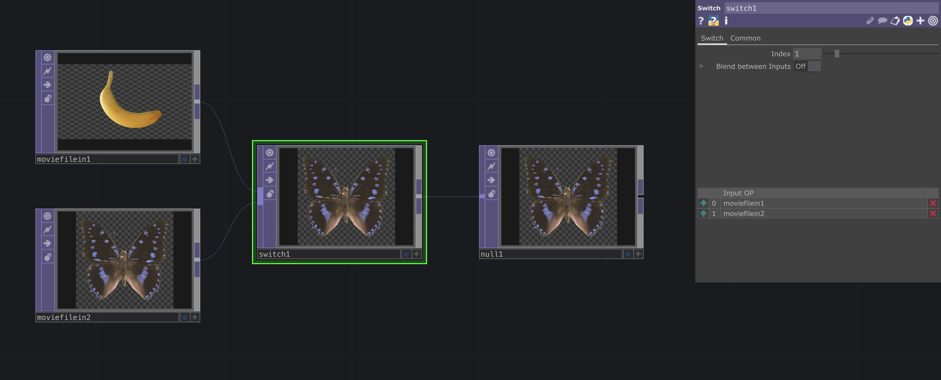
In the parameters window for Switch TOP, use the INDEX slider to alternate between your visuals. Touchdesigner likes to start counting from 0, hence your first image will be indexed as "0" while your second image will be indexed as "1".
As mentioned before, we could use a button, sensor or tracking device to control the operator's INDEX slider.
Other resources
This list of resources will keep on growing as we continue to explore Touchdesigner here at LCC.
The best way to grow in your visual programming journey is to practice! If you're struggling to get started you could look into daily or weekly coding challenges such as the @creativecodeart on Instagram, where a prompt is posted every week and users are invited to submit work in response to it.
Basics:
Touchdesigner's official course: https://learn.derivative.ca/courses/100-fundamentals/
Elekktronaut's Intro to Touchdesigner:https://www.youtube.com/playlist?list=PLFrhecWXVn5862cxJgysq9PYSjLdfNiHz In general all of Elekktronaut's videos are really interesting, useful and beginner friendly.
Main channels for resources:
The interactive & Immersive HQ is a community providing both blogs and videos to learn Touchdesigner: https://youtube.com/playlist?list=PLpuCjVEMQha9_WchDzqG878GtsJd1uJ5s&si=2aMzPXeBErIBhMwh
A collection of Touchdesigner tutorials from all of the internet: https://alltd.org
Tested and approved both free and paid online workshops/seminars: https://musichackspace.org/semantic-search-function/?_products=touchdesigner
Disclaimer: There are plenty of free resources available online, it is not recommended to pay for tutorials at the beginning of your journey.
Cheat Sheets:
Common Python operations: https://matthewragan.com/teaching-resources/touchdesigner/touchdesigner-common-operations-cheat-sheet/
Keyboard Shortcuts: https://matthewragan.com/teaching-resources/touchdesigner/touchdesigner-keyboard-shortcuts/
External components:
Connecting MIDI controller to Touchdesigner: https://www.youtube.com/watch?v=XLeghJmFBh0
AI vision using Media Pipe in Touchdesigner: https://www.youtube.com/watch?v=Cx4Ellaj6kk
Other repositories and useful tools might be Github, a website and drive where coding projects are stored, managed and ofter shared as open-source, and ChatGPT, a potential AI assistant, if instructed with a detailed prompt. These tools can help you move faster in your journey but it's important to be transparent about your process and to credit other developers when appropriate, you can read more about best practice to co-create with AI here: https://nadiapiet.notion.site/Prompt-Etiquette-Guidelines-WIP-52a15db1a1cd43fd940fe2fa96508bf9.
Interactive Media
Audio in Touchdesigner & Receiving data from Arduino
These tutorials aim to introduce some of the basis workflows and practices for working with audio in Touchdesigner, as well as provide students with external resources to continue on their research journey.
The tutorial is structured in 3 main sessions, each made up of a brief video tutorial and a more in-depth written description of some the operators used, as well as some extra tips and tricks to continue experimenting with.
Audio-Reactive Graphics
In this first session we'll set up a network to extract numerical data from an audio sample. The data is later used to animate a graphic, you can quickly test this set up out by animating the radius of a Circle TOP.
While this brief video introduces the basis of extracting numerical values from a audio file, you can further explore the Audio Spectrum CHOP and it's parameters to filter out lower/higher frequencies, detect kicks in your audio file, etc.
Recommended resources: Audio Reactive Drawn Content in TouchDesigner , Make Anything Audio Reactive
Mic-Input
Our laptop's microphone is an easy input to detect voices but can also act as a sensor to detect how many people are in a room or the type of event we are attending. In this second session we continue to work on audio-reactive content but use our microphone as source of input, we will explore how to adjust our new values to the visual.
Generative Sounds, Receiving data from Arduino
In the first two sessions we have explored the possibility of animating with sound, using audio as our source of input. In this session we look at sound as our final output, the result of other interactions happing in a physical realm.
In this example, we begin by connecting a Force sensor to an Arduino and use the sensor to generate numerical values, which we will translate into sounds in Touchdesigner. We will use the Serial DAT operator to access Arduino's port and translate these numbers into CHOP values. We will use these as our interactive point of reference, to manipulate the Frequency of our waveform, from the Audio Oscillator CHOP.
While Touchdesigner might not have been initially designed with audio generation in mind, there are a couple of great resources online to help get some interesting sounds out of it:
Owen Kirby is a audio-visual artist, he explores the audio-synthesis side of TouchDesigner in his YouTube channel and has hosted a super insightful TD meet up in 2020, where he share some files and his process: https://www.youtube.com/watch?v=Xajdyh7kspk.
VSTs are virtual audio-synthesisers that allow you to easily enhance sounds, you can use a Audio VST CHOP to import these onto your network. You can read more about VSTs here.
Sending data to Arduino
When connected with Arduino, Touchdesigner becomes a powerful tool that makes use of external sensors to enhance immersive and interactive experiences. This brief tutorial will walk you through using Firmata, a protocol found both in Arduino IDE and Touchdesigner to enable communication between the softwares through serial.
In Arduino
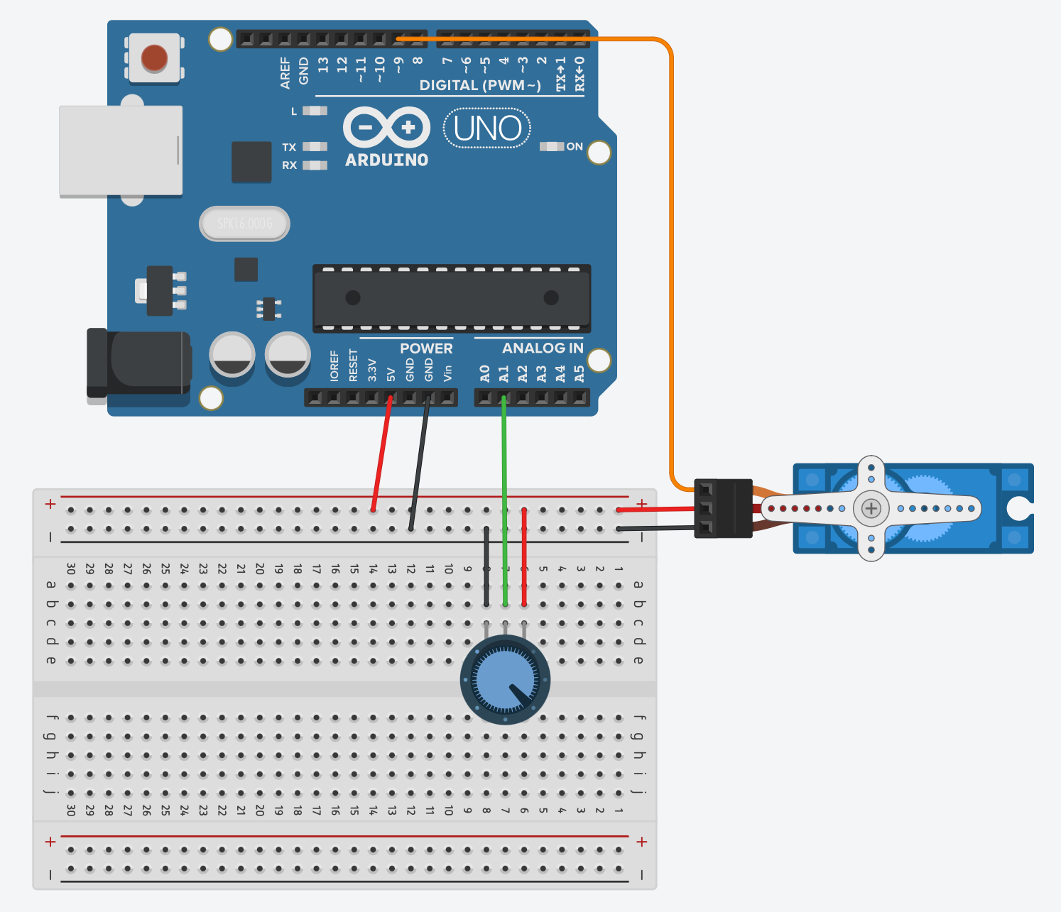
Connect your board to your computer and launch Arduino. Make sure your hardware matches the software by selecting the correct board and port from "Tools". For this tutorial we will connect a potentiometer, as input in our circuit, and a servo motor, as our output, to the Arduino board - It is important to note that, while we will connect these components to both send and receive data through Arduino and influence other another, this is not standard practice, as we will later see.
To load the code choose "File" > Examples, then select Firmata > StandardFirmata. Click on the arrow button ![]() to upload the code.
to upload the code.
In Touchdesigner
A Firmata COMP is available in Touchdesigner to send and receive data through Arduino.
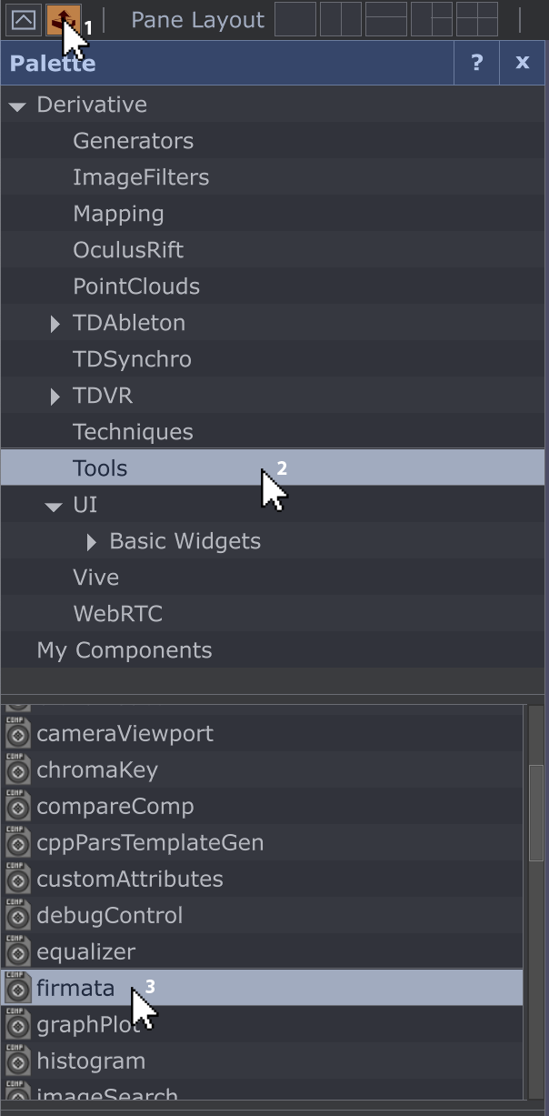 To access it open the Palette and select Tools, where a list of components will appear.
Select firmata, drag and drop it anywhere in the interface. Click "p" on your keyboard to view the parameters window. From the sub-category "Firmata" in Port find the directory of your Arduino board then click on Active to turn on serial communication. To view the status of each pin in your Arduino board click on Pulse next to Query Version.
A list of all available pins will now appear in the operator; The first 17 valuePins correspond to the Digital pins on the Arduino board, while the valuePins between 18 and 23 correspond to the Analog pins on the board. For this reason you might notice some noise in valuePin18, which corresponds to our potentiometer's pin, A0. In the sub-category "Pin Values" find Pin 18 - Analog and "Enable Reporting" to receive data from Arduino, use your potentiometer to change this value.
In the sub-category "Pin Modes" find Pin 9 . Here you will be presented with multiple options, in this case we will select "servo", however if we were using another component we could have selected the more generic "output" option. In the sub-category "Pin Values", use the slider next to Pin 9 to activate your servo motor.
Finally, solelny for this demostration, we will use the potentiometer's value to control our servo; Add a Select CHOP to your Firmata COMP and from Channel Names select valuePin18, next add a Null CHOP - I've renamed it "Potentiometer". Activate the operator, then drag and drop the channel in the parameter Pin 9(Servo) in the Firmata COMP.
As mentioned before, this is not good practice hence we get an error *. A correct practice requires us to either send OR receive data through Arduino to manipulate visuals generated in Touchdesigner or use CHOPs to control external components.
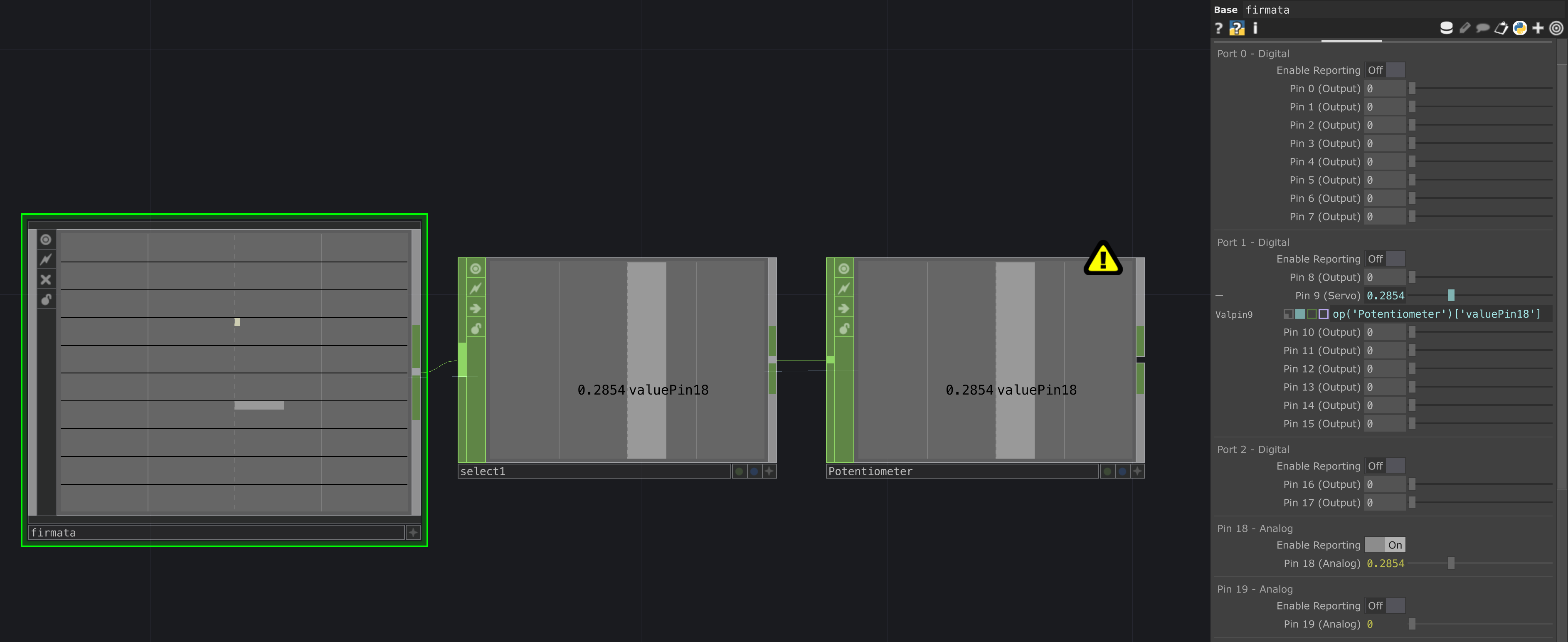
* While our network might still run, the error indicates this practice is not reliable and might fail. If you are interested in controlling a physical output through a physical input you should proceed working in Arduino.
Position-based Tracking using a Webcam
Tracking the position of people or objects can be useful when creating interactive projection mapping projects. In TouchDesigner there are various methods to achieve this; This tutorial will introduce you to some common techniques to determine the position of an object. Let's dive in!
To begin, open the VideoDeviceIn TOP and select your DEVICE in the parameters window - you can read more about operators and the parameters window here. Connect this operator to a Null TOP and activate the Display option by clicking on the blue dot in your node, this will allow you to easily monitor any alterations to your original source.
Object Isolation
The first method focuses on isolating your object by combining various TOPs to eliminate its background. It's important to note that this process begins outside of TouchDesigner, during scene setup in real life; Ensure your background has a solid, contrasting colour to your object.
In Touchdesigner, right-click on the connection line to INSERT a node to your network, here select the Level TOP. This operator is useful to adjust the brightness and contrast of your image. Use the sliders available to create a strong contrast between your object and background. Next add a Threshold TOP and change the COMPARATOR to Greater, then alter the THRESHOLD value to adjust the intensity of this effect. At this point your object should be highlighted in white, while the rest of your image should be transparent.
Tracking
Now that we have isolated our object from it's background we want to look for the white pixels in the image, to determine it's location. To do that we first have to size down our input's resolution, this way we will have less data to analyse while keeping readings accurate. In your network, just before the Threshold TOP, add a Resolution TOP and in the sub-category "Common" select your OUPUT RESOLUTION to be Eighth.
Afterwards add a TopTo CHOP to your threshold and in the sub-category "Crop" select your CROP to be Full Image. This converts the pixels in our image into channels, containing RGBA informations.
Our aim is to determine the position of the coloured pixels, to do so we'll be turning our channels into a table. To your TopTo CHOP node add a ChopTo DAT, this will turn the information retained in our channels into a series of 0s, where the pixels are transparent, and 1s, where the pixels are coloured. You can check your process by covering your camera with your hand, now the table in ChopTo DAT should be showing mostly 1s.
Finally, we want to convert these 1s into X and Y co-ordinates within the image, which acts as our cartesian plane. Add a Constant CHOP and create two channels, let's name these X and Y.
Add an Execute DAT, this should not be connected to your network. Right-click on the node and select "Edit Contents in Textport", delete the current Python code and paste the following in. The comments, preceded by an hashtag, briefly explain the various sections of this script.
# Defining begining of execution
def onFrameStart(frame):
if me.time.frame % 5 == 0:
# Referencing operators in our network
source = op('chopto1')
output = op('constant1')
# Initializing empty lists for rows and columns
rows = []
cols = []
# Looping through the rows and columns of the 'chopto1' operator
for x in range(source.numRows):
for y in range(source.numCols):
# Checking if the value at position (x, y) in 'chopto1' is equal to 1
if source[x, y] == 1:
# If true, add the row and column indices to the respective lists
rows.append(x)
cols.append(y)
# Calculating the center of the selected points
centerx = (max(rows) - ((max(rows) - min(rows)) / 2)) / source.numRows
centery = (max(cols) - ((max(cols) - min(cols)) / 2)) / source.numCols
# Outputting new values to 'constant' operator
output.par.value0 = centerx - 0.5
output.par.value1 = centery - 0.5
returnClose the textport and in the parameters window of Execute DAT, turn on the Frame Start to execute the above Python code at the start of every frame. Your object's x and y co-ordinates are now updated in real-time in the Constant CHOP.
You can now link these values to a TOP shape and composite this with your original webcam input to check out the tracking magic, read more about this process here.
Colour Tracking
If you're planning to track multiple objects within the same area, the object isolation method might not be ideal. Instead you can track by colour; To achieve this, make sure your objects are of contrasting colours, as well as your background.
Our input will once again be our webcam in VideoDeviceIn TOP, this time we will connect to a Level TOP not only to adjust the brightness and contrast, within the sub-category "Pre", but to isolate a specific colour. Have a play with parameters in the sub-categories "Range" and "RGBA", the aim here is to make one colour prevail on all others.
Once your selected object is darker than all others, add a ChannelMix TOP to your network and change the RGBA values here to only display your object (values should be between 0 and 1). At this point your object should be the only item visible in the scene. From here we start tracking, refer to the section above.
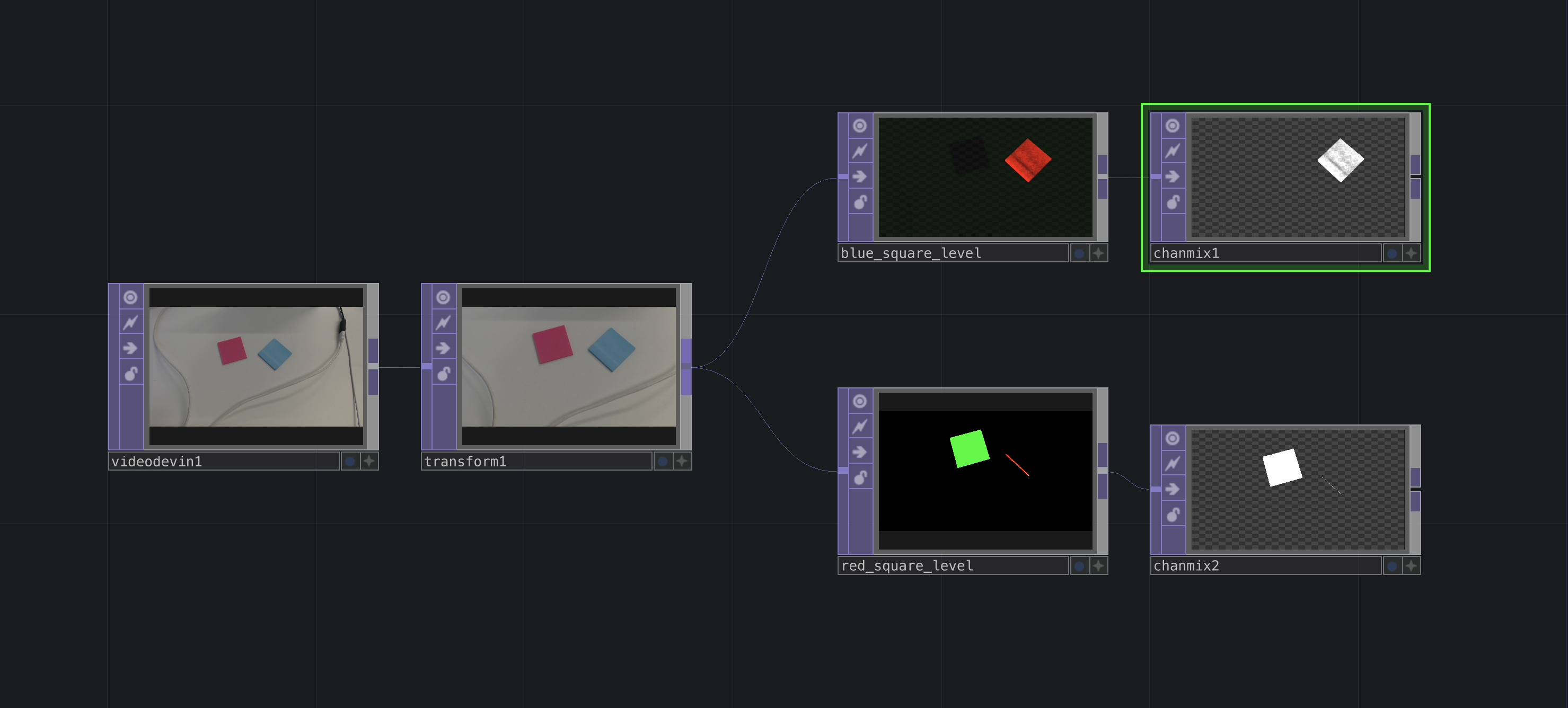
Position-specific detection
If you wish to base your interaction on a specific position, you can use a Circle TOP to generate a placeholder. Assign it a specific colour, in my case I'll be using red, and Composite both your placeholder as well as your tracking shape using the Multiply method; This ensure that when the shape is right above the placeholder it will show up as red. Add an Analyze TOP and convert it into a CHOP to access a numerical trigger, use it to make a video start playing, to switch to another graphic, etc.
![]()
Setting up Kinect in Touchdesigner
External sensors can help us integrate 3D notions such as depth within our graphics. In this tutorial we will look into setting up and using Kinect v2 and some of the other sensors available in CTL. Before we begin, it's important to note that unfortunately these devices are only compatible with Windows machines, however students can arrange with us to use the PCs available in the lab.
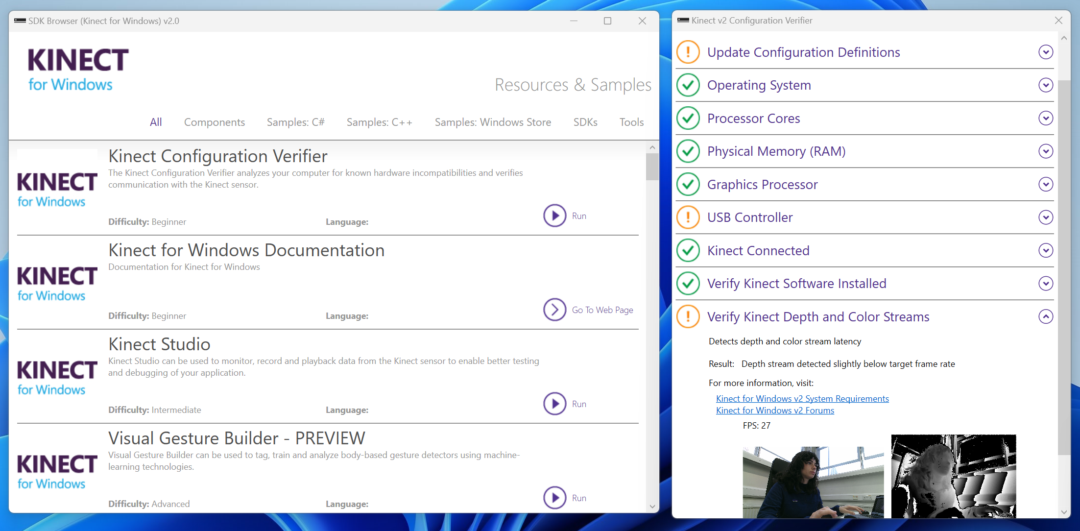
Before we start, download the Software Development Kit (SDK) from here, if using Windows 8 or later versions. Open the app SDK Browser v2.0 and find the Kinect Configuration Verifier component, then hit run. A new window will come up; Here allow some time for the software to upload and update the status of your Kinect. My final settings looked like this (further help setting up Kinect is also available here.
Kinect Studio, in the same list of components available from the SDK Browser, is another useful feature to develop immersive and interactive projects. Kinect Studio lets you record and loop a short video to feed Touchdesigner, helping you smoothly program interactions without having to constantly move in front of the sensor.
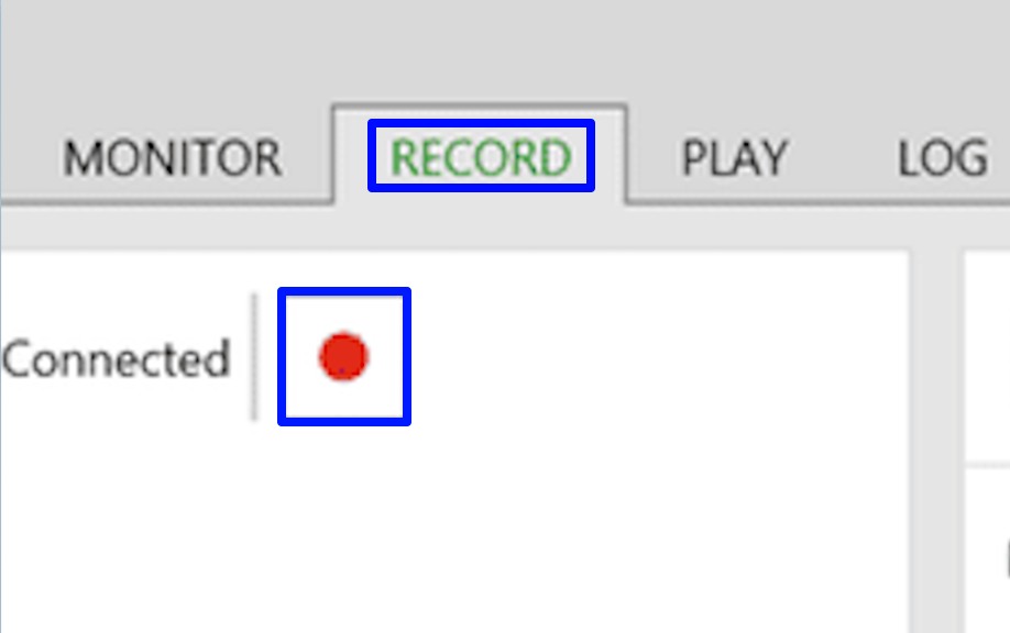
Click run to launch the app and in the top left corner of the interface, click on this button ![]() to connect your sensor. You are now presented with a depth map, from the heading select Record and hit the record button.
to connect your sensor. You are now presented with a depth map, from the heading select Record and hit the record button.
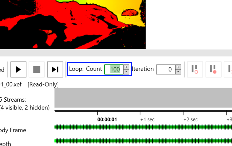
Once you've stopped recording move to the Play section of the interface and change the count to loop your video.
Your recording is now ready! Launch Touchdesigner and select Kinect TOP to view your recording, make sure that your hardware's version corresponds to your sensor, in the lab we offer both Kinect v1 and v2.
Depth Camera for Mac Users: Setting Up the OAK-D Pro in TouchDesigner
If you've worked with TouchDesigner before you would have surely stumbled across some Kinect tutorial and might have been disappointed to discover it is only compatible with Windows. The Creative Technology Hub now offers students the chance to borrow an OAK-D Pro camera. These IR depth cameras are compatible with both Mac and Windows, making them a great alternative to Kinects. This page will briefly guide you through installing the prerequisites and show you how to set your camera up in TouchDesigner.
1. Installing Dependencies
Before using the OAK-D Pro with TouchDesigner, you'll need to install some dependencies:
-
Python 3.8+
-
DepthAI Library
Assuming you've already installed Python and pip, you can check your Python version by opening the terminal and typing:
pyhton --version If your version is older than 3.8, make sure to upgrade it. Next, install the DepthAI library by typing:
pip install depthaiAt this point, it's good practice to restart your laptop before launching TouchDesigner.
2. Setting up TouchDesigner
2.1 Connecting the Camera
-
Connect the OAK-D Pro camera to your laptop using a USB-C to USB-A or USB-C to USB-C cable.
-
Launch TouchDesigner.
2.2 Using OAK Device CHOP
-
From the Operators panel, find the OAK Device CHOP.
-
Activate the CHOP, refresh the sensor list, and find your camera.
-
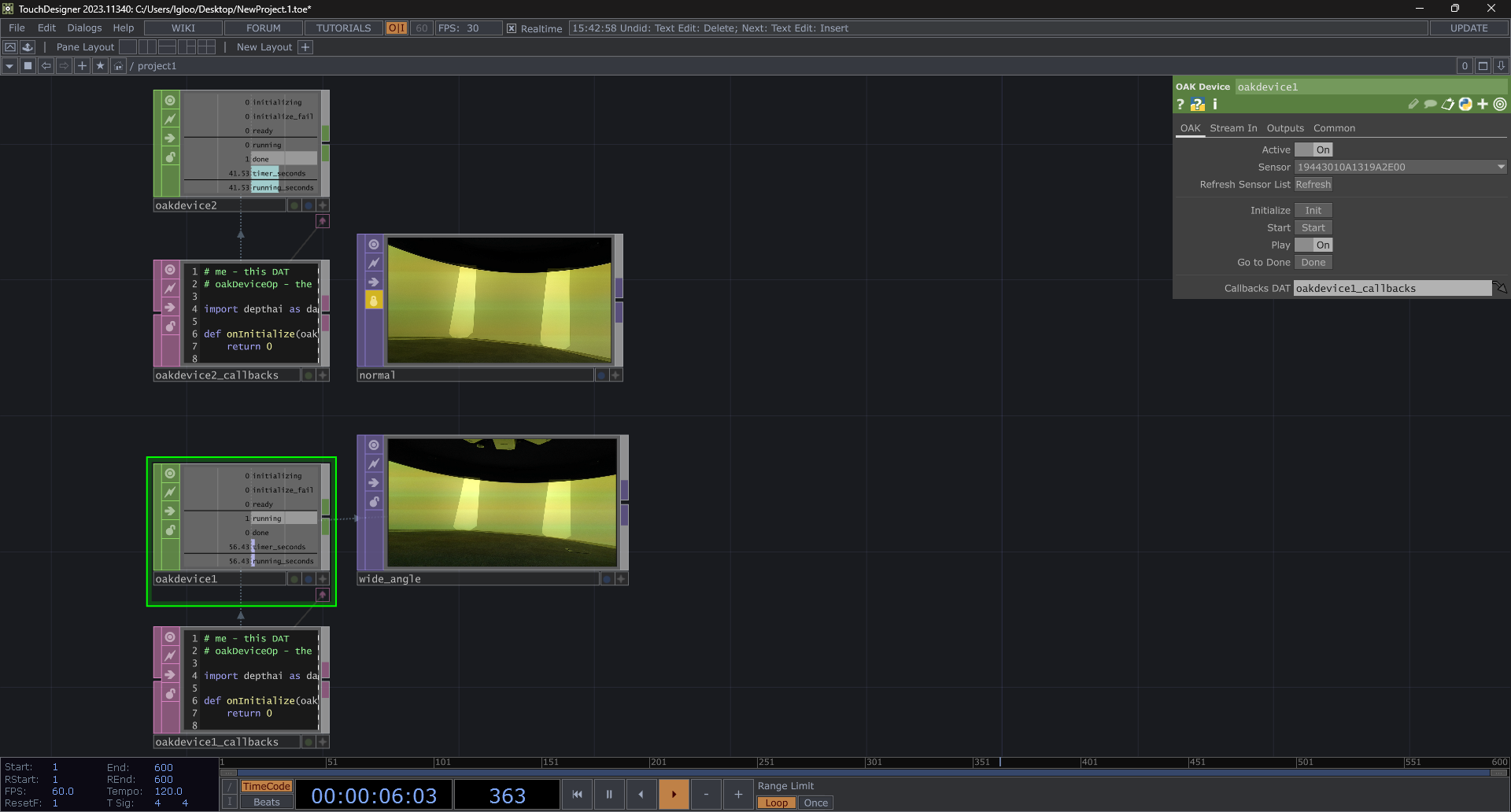
Click Initialize, wait for it to mark "Ready" (1), then press Start.
This CHOP runs a script in Text DAT that captures RGB data from the camera using the DepthAI library.
2.3 Displaying Data in TouchDesigner
-
From the Operators panel, find the OAK Select TOP.
-
Open its parameter window.
-
Drag and drop your OAK Device CHOP into the OAK Select TOP parameter 'OAK Device CHOP'.
-
Click the arrow next to the Stream parameter and select
'rgb'. -
Your camera should now be running!
3. Capturing a Depth Map
Next, we'll program the camera to create a grayscale depth map using it's stereo vision. In fact, this camera has two monochrome sensors that capture images from slightly different angles. By comparing these two images, the camera calculates 'disparity' - the difference in position between matching points in the left and right images - which is then used to determine depth. In the grayscale image the brightness of each pixel represents the distance of objects from the camera. Lighter areas are closer, and darker areas are farther away.
To gather both 'disparity' and 'rgb' data, replace the code in Text DAT with the following:
import depthai as dai
def onInitialize(oakDeviceOp, callCount):
return 0
def onInitializeFail(oakDeviceOp):
parent().addScriptError(oakDeviceOp.scriptErrors())
return
def onReady(oakDeviceOp):
return
def onStart(oakDeviceOp):
return
def whileRunning(oakDeviceOp):
return
def onDone(oakDeviceOp):
return
def createPipeline(oakDeviceOp):
# Create pipeline
pipeline = dai.Pipeline()
# Define nodes for RGB stream
camRgb = pipeline.create(dai.node.ColorCamera)
xoutRgb = pipeline.create(dai.node.XLinkOut)
xoutRgb.setStreamName('rgb')
# Define nodes for Stereo Depth stream
monoLeft = pipeline.create(dai.node.MonoCamera)
monoRight = pipeline.create(dai.node.MonoCamera)
depth = pipeline.create(dai.node.StereoDepth)
xoutDepth = pipeline.create(dai.node.XLinkOut)
xoutDepth.setStreamName('disparity')
# Configure RGB camera node
camRgb.setPreviewSize(1280, 720)
camRgb.setBoardSocket(dai.CameraBoardSocket.RGB)
camRgb.setFps(30)
# Configure Stereo Depth nodes
monoLeft.setResolution(dai.MonoCameraProperties.SensorResolution.THE_800_P)
monoLeft.setBoardSocket(dai.CameraBoardSocket.LEFT)
monoRight.setResolution(dai.MonoCameraProperties.SensorResolution.THE_800_P)
monoRight.setBoardSocket(dai.CameraBoardSocket.RIGHT)
# Configure Depth node
depth.setDefaultProfilePreset(dai.node.StereoDepth.PresetMode.HIGH_DENSITY)
depth.initialConfig.setMedianFilter(dai.MedianFilter.KERNEL_7x7)
depth.initialConfig.setConfidenceThreshold(240)
depth.setLeftRightCheck(True)
depth.setExtendedDisparity(False)
depth.setSubpixel(False)
# Linking RGB camera to output stream
camRgb.preview.link(xoutRgb.input)
# Linking Mono cameras to depth node
monoLeft.out.link(depth.left)
monoRight.out.link(depth.right)
# Linking depth output to disparity stream
depth.disparity.link(xoutDepth.input)
return pipeline
Once you've replaced the script:
-
Click the arrow next to the Stream parameter in OAK Select TOP.
-
Select
'disparity'to visualize depth data. -
To display the
'rgb'stream simultaneously, create a second OAK Select TOP and select'rgb'as the stream.
3. Conclusion
The OAK-D Pro is a fantastic alternative to the Kinect for Mac users working with TouchDesigner. At this stage you should be able to set this camera up and follow along any Kinect tutorial!
Capturing in Wide-Angle with the OAK-D Pro camera
If you haven’t already, please complete all the prerequisites outlined in our introduction to the OAK-D Pro camera before starting this tutorial. Refer to the guide to set up the OAK Device CHOP and OAK Select TOP components.
In this tutorial, we’ll program the camera to generate a wide-angle image using its vision system. To do this, replace the script in the Text DAT with the following code:
import depthai as dai
def onInitialize(oakDeviceOp, callCount):
return 0
def onInitializeFail(oakDeviceOp):
parent().addScriptError(oakDeviceOp.scriptErrors())
return
def onReady(oakDeviceOp):
return
def onStart(oakDeviceOp):
return
def whileRunning(oakDeviceOp):
return
def onDone(oakDeviceOp):
return
def createPipeline(oakDeviceOp):
pipeline = dai.Pipeline()
cam = pipeline.create(dai.node.ColorCamera)
xoutIsp = pipeline.create(dai.node.XLinkOut)
xoutPrev = pipeline.create(dai.node.XLinkOut)
xoutIsp.setStreamName('isp')
xoutPrev.setStreamName('preview')
cam.setResolution(dai.ColorCameraProperties.SensorResolution.THE_12_MP)
cam.setInterleaved(False)
cam.setIspScale(1, 2)
cam.setPreviewKeepAspectRatio(False)
cam.setPreviewSize(1280, 720) # or any desired preview resolution
cam.preview.link(xoutPrev.input) # wide-angle output
return pipelineOnce you've replaced the script:
-
Click the arrow next to the Stream parameter in OAK Select TOP.
-
Select
'preview'to visualise the wide-angle image.