How to connect a Push Button with Digital Input Pull-Up resistor
What is areDigital pushInput buttons/switches?Pull-Up resistor?
ButtonsIn and switches areArduino, a wayDigital ofInput openingPull-Up andResistor closingis aan circuit,internal i.e.resistor making and breaking a connection as one of the most rudimentary forms of sensorthat you can useenable withon andigital Arduino.input pins to ensure a known default voltage level (HIGH) when the pin is not actively connected to anything (i.e. it’s “floating”).
ThereWe arehave dozensanother tutorial showing how to use a button the normal way.
Advantage of differentusing types of switches and buttons, but at their most basic is the momentary pusha button whichthis we'llway
-
onFewer
inExternalthe wiring and getting started sections below. However the same approach applies to these as it does to any other type of button or switch.ComponentsDifferent typesRockerNoswitchneed for an external resistor—the internal pull-up does the job.PushMakesbuttoncircuits Tactilesimplerbuttonand Reedsavesswitchspace, Tiltespeciallyswitchon Keyaoperated switchRotary switchSlide switchMicro switchToggle switchbreadboard.
There -
PushStablebuttonsDefault State (HIGH)like- Ensures
foundtheininput pin has acomputerknownkeyboardstateare really useful for activating an action, like a start video button.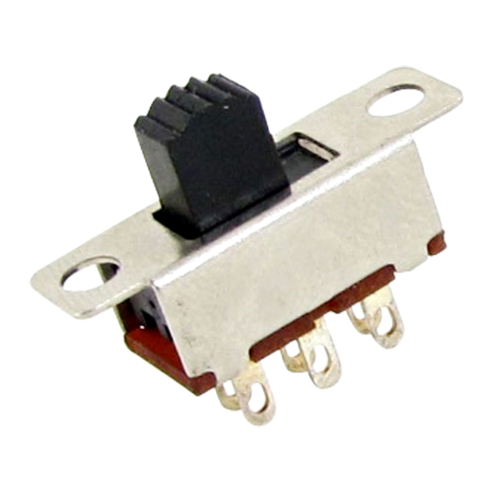
Rocker, slide and toggle switcheswork more like light switches holding their position, they can be a good way of indicating the mode of a device, such as playing video forward or backwards.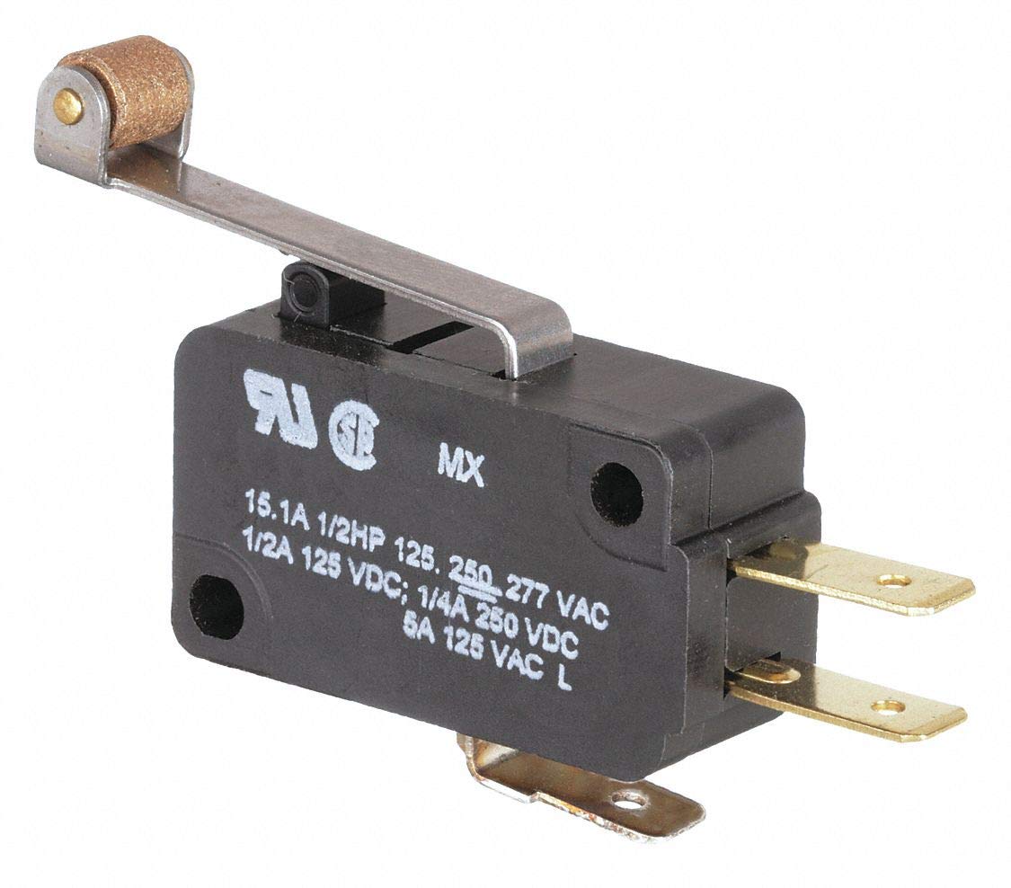
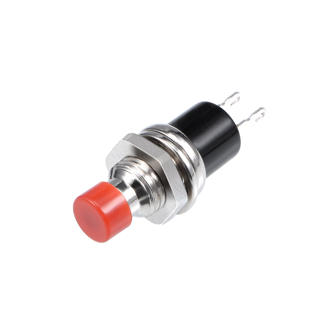
Micro switchescan with motors to detect when it has reached the end of movement, such as in a 3D printer to stop the motor going too far over the end, or to detect if a draw is open or closed.WiringAlthough a push button like that in the diagram only has two connections, which are closed by pressing the button, you have to add a resistor to make the circuit work properly. - Prevents
isfloatingbrokeninputs,andwhichthecanwirecausetorandomtheorArduinonoisyisreadings.
thosecircuitknownas - Ensures
-
theSimpler
voltageWiringis- You
so weonly need toconnect it to ground to ensure the Arduino reads 0V.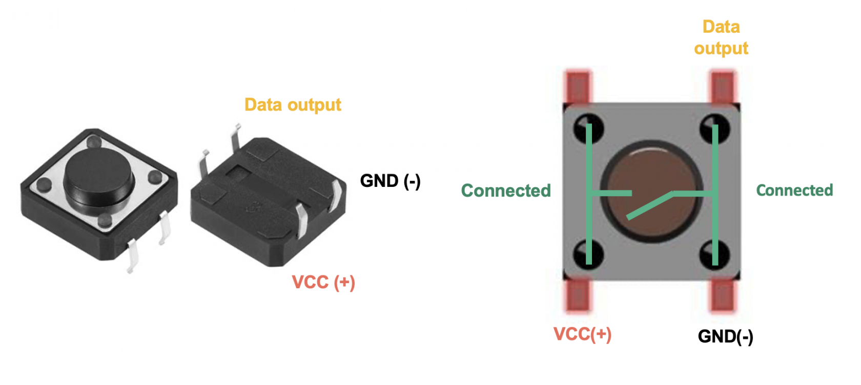
It's not possible however to do this otherwise when you apply 5V by closing the circuit you would create a short circuit, instead we connect the Arduino pin through a high value 10KΩ resistor to ground, this allows the circuit to quickly reach 0V whenwire the buttonis released but prevents large amounts of current flowing whenbetween thebuttonpin and GND. - Ground is
pressed.often
easier to route in a circuit than Vcc (especially with many buttons).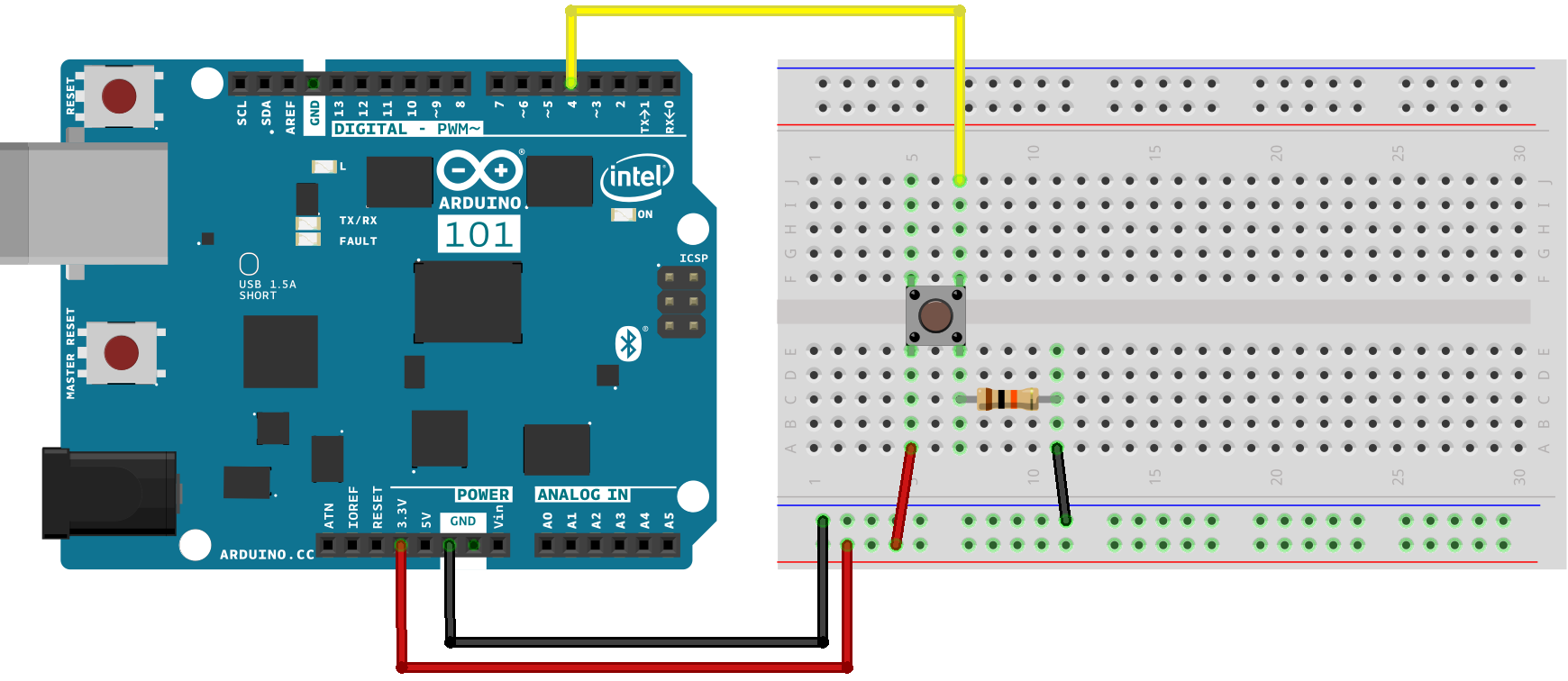
indeterminate, - You
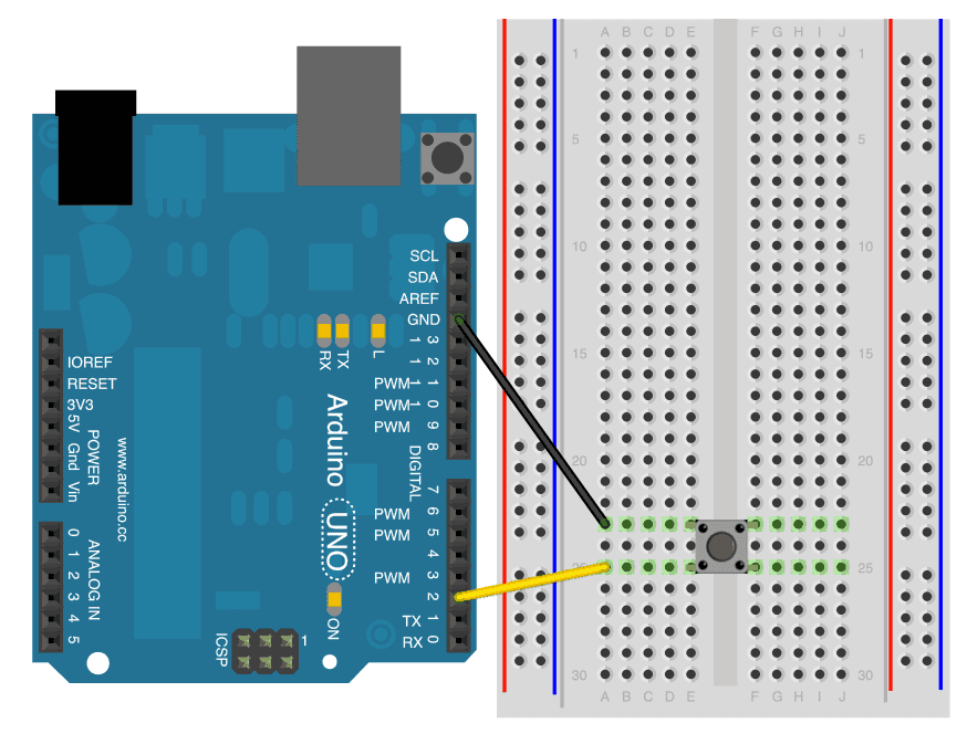
Wiring
- one pin to GND
- one pin to 2

Getting started
The following is a simple circuit that will get your button controlling the LED built into the Arduino.
#define ledPin 13
#define buttonPin 4

void setup() {
  pinMode(2, ledPin, OUTPUT )INPUT_PULLUP); pinMode(// buttonPin,Internal INPUTpull-up )enabled
  Serial.begin(9600);
}

void loop() {
  booleanint btnStatebuttonState = digitalRead( buttonPin )2);
  ifSerial.println(buttonState); (// btnState ==Reads HIGH )when {not digitalWrite( ledPin, HIGH );
  } else {
    digitalWrite( ledPin,pressed, LOW )when pressed (to GND)
  delay(100);
  }
}
If you want to add a toggle functionality such that one press causes the LED to come on, and another press then turns it off, so you don't have to hold the button down things get a little bit more complex.
The Arduino is a powerful computer and operates many times faster than human perception, as such when the mechanical push button is closed there is a small amount of 'bounce' where the circuit makes and breaks the connection a few times before it settles, this is detected by the Arduino as multiple presses.

This diagram shows the signal bouncing up and down over a period of 10µS (0.00001 seconds)
In effect this means that each time you press the button to toggle just once it toggles multiple times, you can fix this either with a small capacitor, or modifications to your Arduino sketch.
The code here adds two major changes, first it tracks the current and previous button state through each loop meaning it can see if the button has changed from LOW to HIGH, and then adds a delay of 75ms to allow the button to settle but keep it fast enough that the user doesn't perceive this delay.
#define ledPin 13
#define buttonPin 4

boolean ledState = LOW;
boolean prevBtnState = LOW;

void setup() {
  pinMode( ledPin, OUTPUT );
  pinMode( buttonPin, INPUT );
}

void loop() {
  boolean btnState = digitalRead( buttonPin );

  if ( btnState == HIGH && prevBtnState == LOW ) {
    ledState = ! ledState;
    delay( 75 );
  }

  digitalWrite( ledPin, ledState );

  prevBtnState = btnState;
}