How to hack a brainwave EEG toy - Force Trainer II
What is a potentiometer?NeuroSky Brainwave?
ANeuroSky potentiometer (often abbreviated to pot) is an electronic component with three connections, the main purpose of the pot is to create a variable voltage as an input to a circuit, for example controlling how loud your speakers should be.
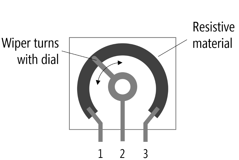
Inside a potentiometerBrainwave is a largetechnology resistivethat areauses betweenEEG pin(Electroencephalography) #1sensors to detect electrical activity in the brain. The NeuroSky chip processes these brain signals and #3,translates them into digital data, which can be used in applications like gaming, meditation tracking, and brain-computer interfaces (BCIs).
Although the middleactual pin #2headset is calledquite pricey, the wiper,NeuroSky and by actuating the pot youchip can select a position along that resistive area to create a proportional to the voltage between pins #1 and #3.
For example if you have Ground (0V) on pin #1, and 5V on pin #3, you could select a voltage between 0V to 5V, at the half way the voltage on pin #2 would be 2.5V.
Different types
There are two main types:
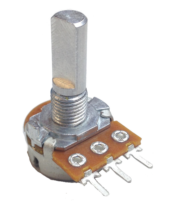
Rotary Potentiometers like those found on speakersbrainwave-controlled totoys controlsuch as the volume.

SlideForce PotentiometerTrainer. likeThe thosetoy foundcan be hacked with a arduino. This tutorial is based on audioJimRosKind's mixingtutorial.
desks.
Wiring
WiringIn upthis buttonstutorial, andwe switchesare using an UNO, hardware Serial (pins 0 & 1) is simple,shared both are fundamentallywith the same,USB howeverconnection, ittherefore can be tricky identifying pins #1, #2, and #3 (more on this later).
At its most basic, pins #1 and #3we need to beuse connectedsoftware serial to Powercommunicate with the NeuroSky chip.
- Solder a wire from the T pin (red circle) on the chip and
Ground,connectforthatexamplewire5VtoandpinGND2 onanArduino - Solder
Pina#2wire from thewiper-needs(purpletocircle)beonconnectedthe chip next to theanalogbatteryinputandpinsconnect(eg.thatA0-A5 for Arduino UNO).Rotary Potentiometer Wiring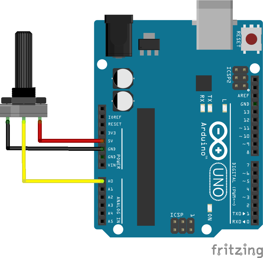
Slide Potentiometer Wiring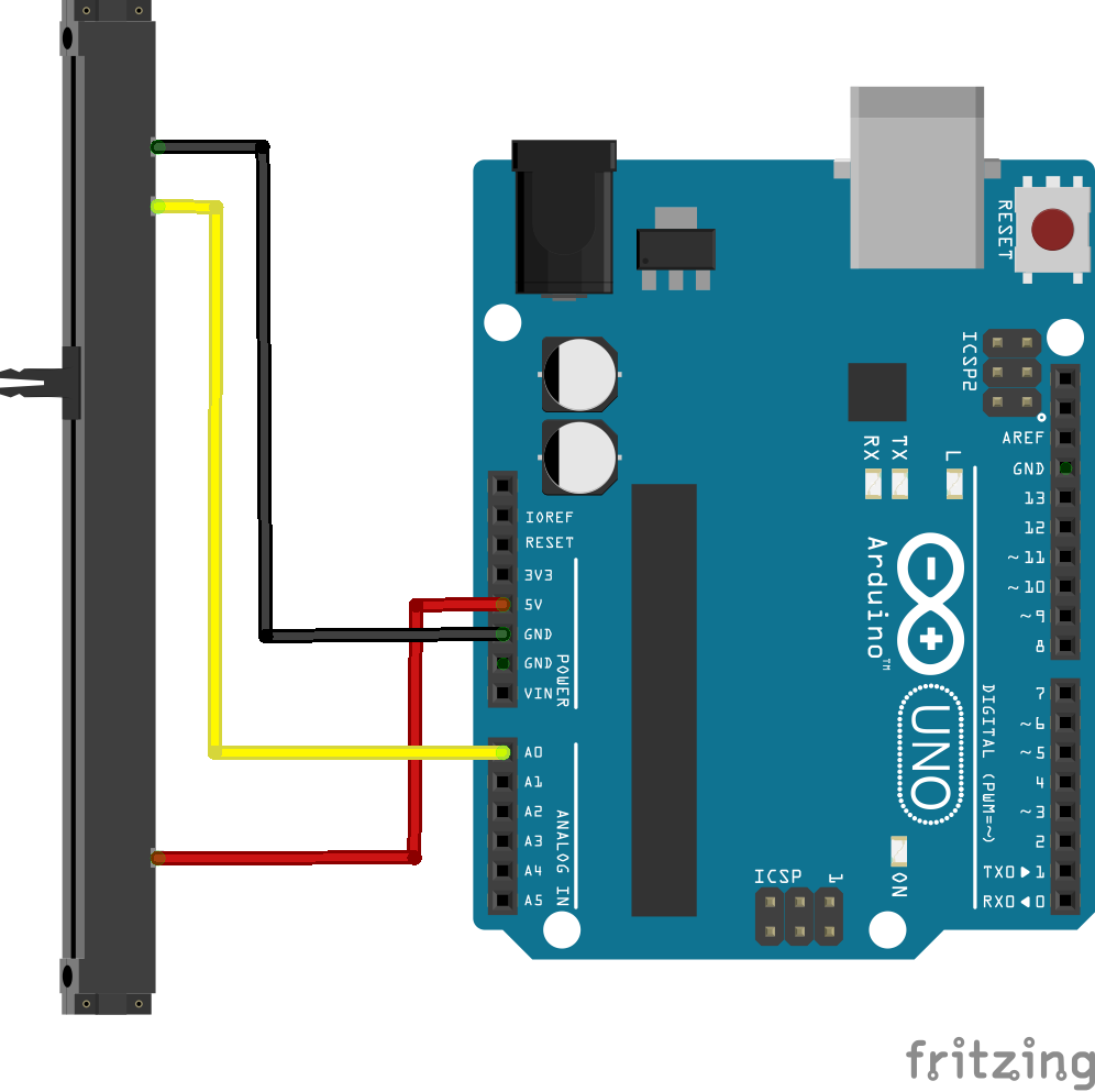
Identifying the pins of a potentiometerThe most common type of potentiometerwire touse is a 10KΩ potentiometer, that means the resistance between pin #1 and #3 is fixed at 10KΩ or thereabouts, and that the resistance between pin #2 and either of the other two will be proportional to the position of the potentiometer rotation/sliding.In other words, using a multimeter set to resistance/ohms/Ω measurement you can find the two pins that don't change at all, and measure a resistance close to the rating markedGND onit.Arduino.

Getting started
The following is a simple sketch that will getprint a potentiometer controllingout the LEDsignal builtquality, intoattention theand Arduino.
This sketch will make the LED blink at a rate between 0ms to 1023ms, this is because the function analogRead returns a value between 0-1023.data.
#define#include ledPin<SoftwareSerial.h>

13// #defineDefine potPinthe A0RX/TX pins for SoftwareSerial
SoftwareSerial mindwaveSerial(2, 3); // RX, TX

void setup() {
  pinMode( ledPin, OUTPUT )Serial.begin(57600);       pinMode(// potPin,Serial INPUTmonitor )baud rate
  mindwaveSerial.begin(57600); // NeuroSky baud rate
}

void loop() {
  digitalWrite( ledPin, HIGH readMindwave();
delay(}

analogRead(void potPin readMindwave() {
  static int state = 0;
  static byte payload[256];
  static int payloadLength = 0, payloadIndex = 0;
  static byte checksum = 0;

  while (mindwaveSerial.available()) {
    byte byteRead = mindwaveSerial.read();

    digitalWrite(switch ledPin,(state) LOW{
      case 0: // Waiting for first sync byte (0xAA)
        if (byteRead == 0xAA) state = 1;
        break;

      case 1: // Waiting for second sync byte (0xAA)
        if (byteRead == 0xAA) state = 2;
        else state = 0;
        break;

      case 2: // Read payload length
        if (byteRead > 169) { // Invalid length, reset
          state = 0;
        } else {
          payloadLength = byteRead;
          payloadIndex = 0;
          checksum = 0;
          state = 3;
        }
        break;

      case 3: // Read payload
        payload[payloadIndex++] = byteRead;
        checksum += byteRead;
        if (payloadIndex == payloadLength) state = 4;
        break;

      case 4: // Verify checksum
        checksum = ~checksum & 0xFF; // Compute checksum
        if (checksum == byteRead) {
          processPayload(payload, payloadLength);
        }
        state = 0;
        break;
    }
  }
}

void processPayload(byte *payload, int length) {
  for (int i = 0; i < length; i++) {
    byte code = payload[i];

    if (code == 0x02) {  // Signal Quality
      int signalQuality = payload[++i];
      Serial.print("Signal Quality: ");
      delay(Serial.println(signalQuality);
    analogRead(}
    potPinelse )if (code == 0x04) {  // Attention
      int attention = payload[++i];
      Serial.print("Attention: ");
      Serial.println(attention);
    }
    else if (code == 0x05) {  // Meditation
      int meditation = payload[++i];
      Serial.print("Meditation: ");
      Serial.println(meditation);
    }
  }
}