How to use a Servo Motor
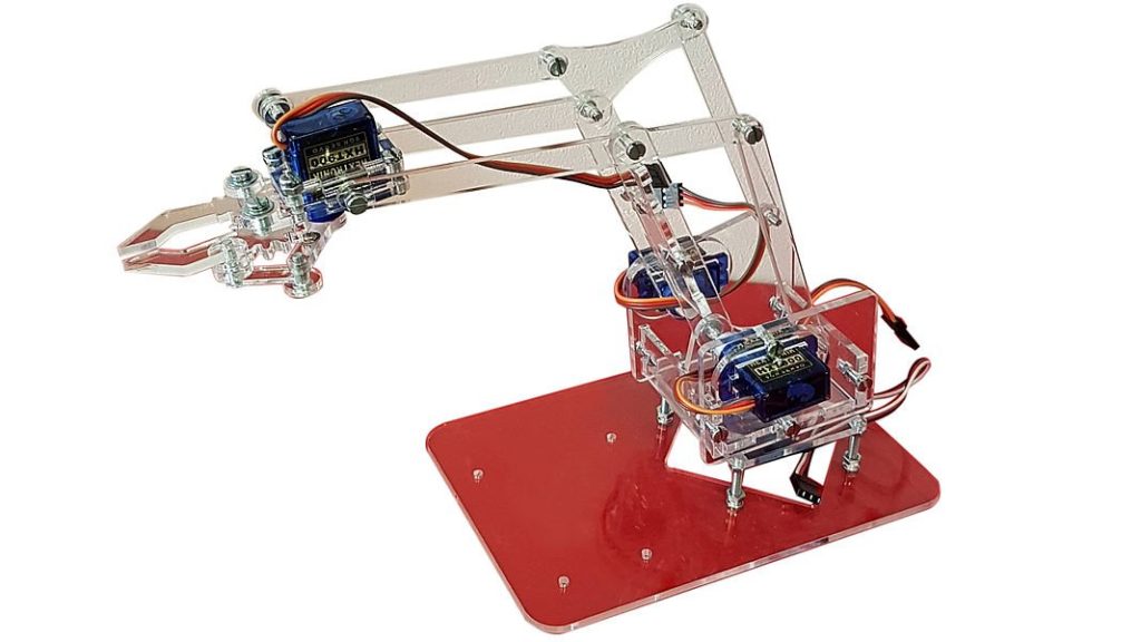
HowWhat to constructis a roboticServo arm?Motor?
A simpleservo robotic armmotor is basicallya likerotary actuator that allows for precise control of angular position, velocity, and acceleration. It is commonly used in robotics, CNC machinery, conveyor belts, and various automation systems. A servo motor works by receiving a humancontrol armsignal whichthat consistsrepresents a desired output position, and it uses an internal feedback system to adjust the motor’s movement accordingly. We often use RC (Radio-Controlled) Servo Motors in physical computing.
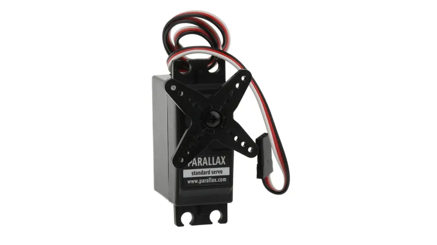
Types of theCommon upperRC arm,Servo lowerMotors
| Servo Type | Rotation Range | Control Type | Common Use |
|---|---|---|---|
| Regular ( |
0°–180° (sometimes 270°) | Angular position (PWM) | Arms, steering, gimbals |
| Continuous Rotation Servo | 360° (infinite) | Speed & direction (PWM) | Wheels, drive systems |
| Mini / Micro Servo | Depends on type (limited or continuous) | Same as regular or continuous | Small robots, drones, model planes |
Using a lotPWM ofDriver
You may come across many online resources for laser-cut filestutorials that you can use. After you have found one or designed one, you can go to the 3D Workshop to laser cut the hardware. In this tutorial, we will focus onshow how to control the servo motor (the joint of your robotic arm) with two potentiometers.
You can use more or less servo motors directly without a PWM driver. While this method is possible, it’s not the most reliable—especially when working with multiple servos. Sooner or later, you’re likely to run into issues, often related to power management and signal stability.
For this reason, in your design based on how many joints you need. In this tutorial, wewe’ll willbe using the Seeed Studio 16-channel PWM driver for more stable and scalable control. You can also use twoother servosimilar motors,PWM onedriver forboards thedepending rotationon atyour theneeds.
base and one for the angle of the upper arm.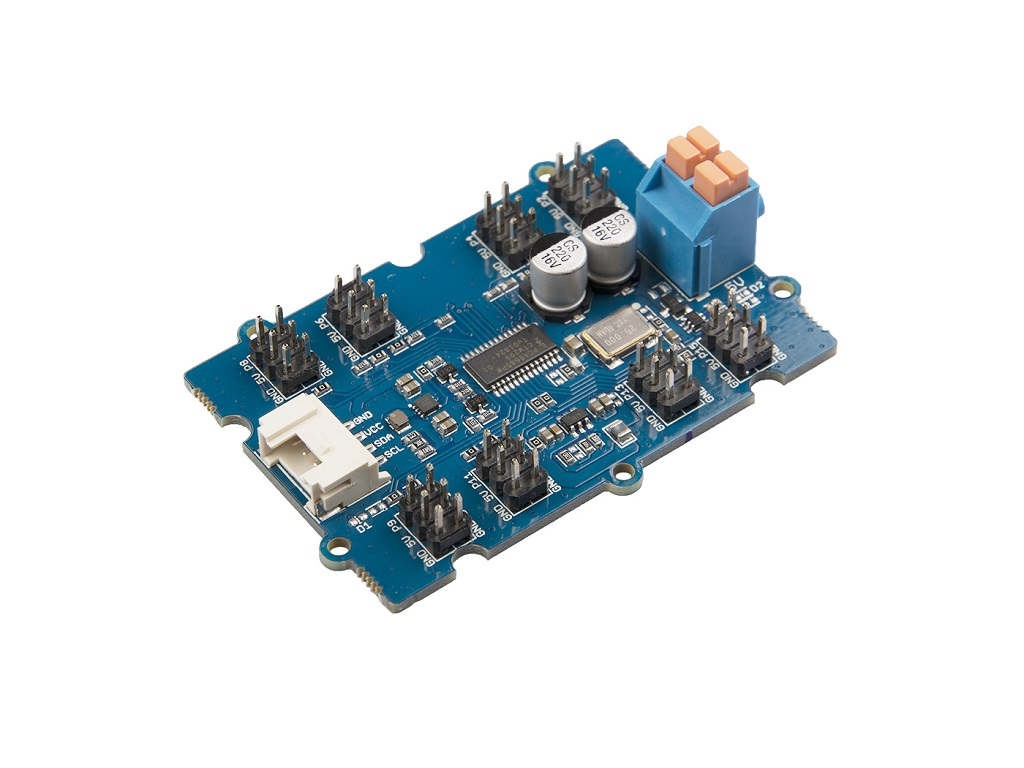
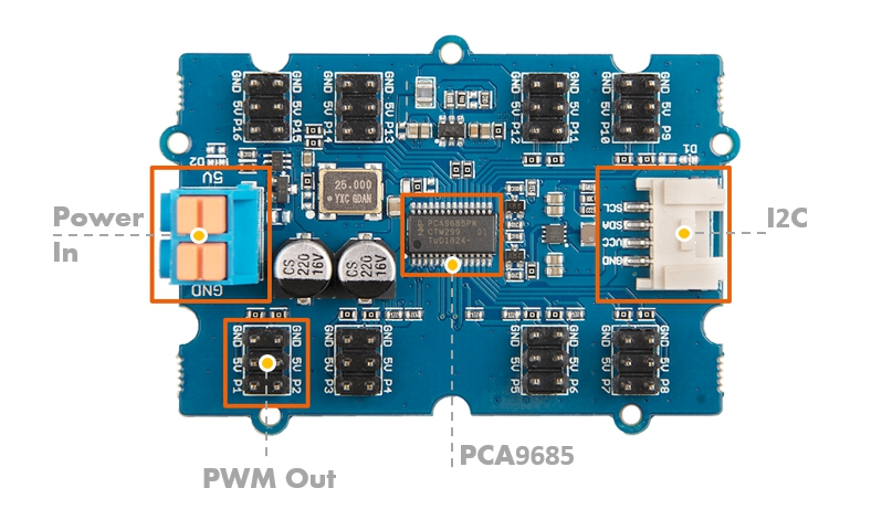
Wiring
-
Servo:5V Power Supply on the Left:Power-
+to 5V -
-to GND
-
-
Servo:i2C to Arduino on the Right:Ground- GND to GND
Servo:Signal to 6/10Potentiometer:Right pin5V to 5VPotentiometer:Left pinSCL toGNDSCL- SDA to SDA
-
Potentiometer:Middle pinServo toA0/A1PWM Out:- Plug in the servo, where the black wire goes to the GND
Library
Grove-16-Channel_PWM_Driver-PCA9685 library will be used.
We have a tutorial on how to install a library here.
Getting started - Regular Servo
This code is getting the eight servo motors to rotate basedto on0 thedegrees potentiometers'and values.then 90 degrees, one by one.
#include "PCA9685.h"
#include <Servo.Wire.h>

#defineServoDriver potRotation      A0
#define potAngle      A1
#define servoRotation  10
#define servoAngle  6

// create servo object to control a servo
Servo rotateServo;
Servo angleServo;servo;

void setup()
{
    // join I2C bus (I2Cdev library doesn't do this automatically)
    Wire.begin();
    Serial.begin(9600) ;
    rotateServo.attach(servoRotation);
  angleServo.attach(servoAngle)servo.init(0x7f);
}

void loop()
{
    // readDrive analog8 potentiometerservos valuesin turns
    for (int rotationi = analogRead(potRotation)1; i < 9; i++)
    {
        servo.setAngle(i, 0);
        int angle = analogRead(potAngle)delay(1000);
        intservo.setAngle(i, rotationMapped = map(rotation, 0, 1023, 0, 180)90);
        // scale it to the servo's angle (0 to 180)
  int angleMapped = map(angle, 0, 1023, 0, 180); // scale it to the servo's angle (0 to 180)

  rotateServo.write(rotationMapped); // rotate servo motor 1
  angleServo.write(angleMapped); // rotate servo motor 2

  // print data to Serial Monitor on Arduino IDE
  Serial.print("potRotation: ");
  Serial.print(rotation);
  Serial.print(", potAngle:");
  Serial.print(angle);
  Serial.print(" => Servo Motor Rotation: ");
  Serial.print(rotationMapped);
  Serial.print("°, Angle:");
  Serial.print(angleMapped);
  Serial.println("°")delay(1000);
    }
}
Getting started - Continuous Servo
Since a continuous servo is controlled by a pulse, the ‘degree’ values work differently. Values like 0, 90, and 180 don’t represent angles; instead, they typically control rotation direction and speed — for example, 0 means full speed clockwise, 90 means stop, and 180 means full speed counterclockwise.
The below code is getting the servo motor 1 rotates clockwise for 1 second and stop for 1 second.
#include "PCA9685.h"
#include <Wire.h>

ServoDriver servo;

void setup()
{
    // join I2C bus (I2Cdev library doesn't do this automatically)
    Wire.begin();
    Serial.begin(9600);
    servo.init(0x7f);

    //Most continuous servo motors' pulse width is 900-2100
    servo.setServoPulseRange(900,2100,180);
}

void loop()
{
    // Drive 8 servos in turns
        servo.setAngle(1, 0);
        delay(1000);
        servo.setAngle(1, 90);
        delay(1000);

}