Radio Communication: How to use APC220 Radio Data Module
What is aAPC220 ServoRadio Motor?Data Module?
AThe servoAPC220 motorRadio Data Module is a rotarycompact, actuatorlow-power, thatwireless allowstransceiver module designed for preciseserial controlcommunication ofover angularlong position,distances velocity,using andthe acceleration.433 ItMHz isISM band. It’s commonly used infor robotics,Arduino CNC machinery, conveyor belts,projects and variouswireless automationsensor systems.networks, Aespecially servo motor works by receivingwhere a controlsimple signalUART that represents a desired output position,interface and itlong-range usescommunication anare internalneeded.
feedback system to adjust the motor’s movement accordingly. We often use RC (Radio-Controlled) Servo Motors in physical computing.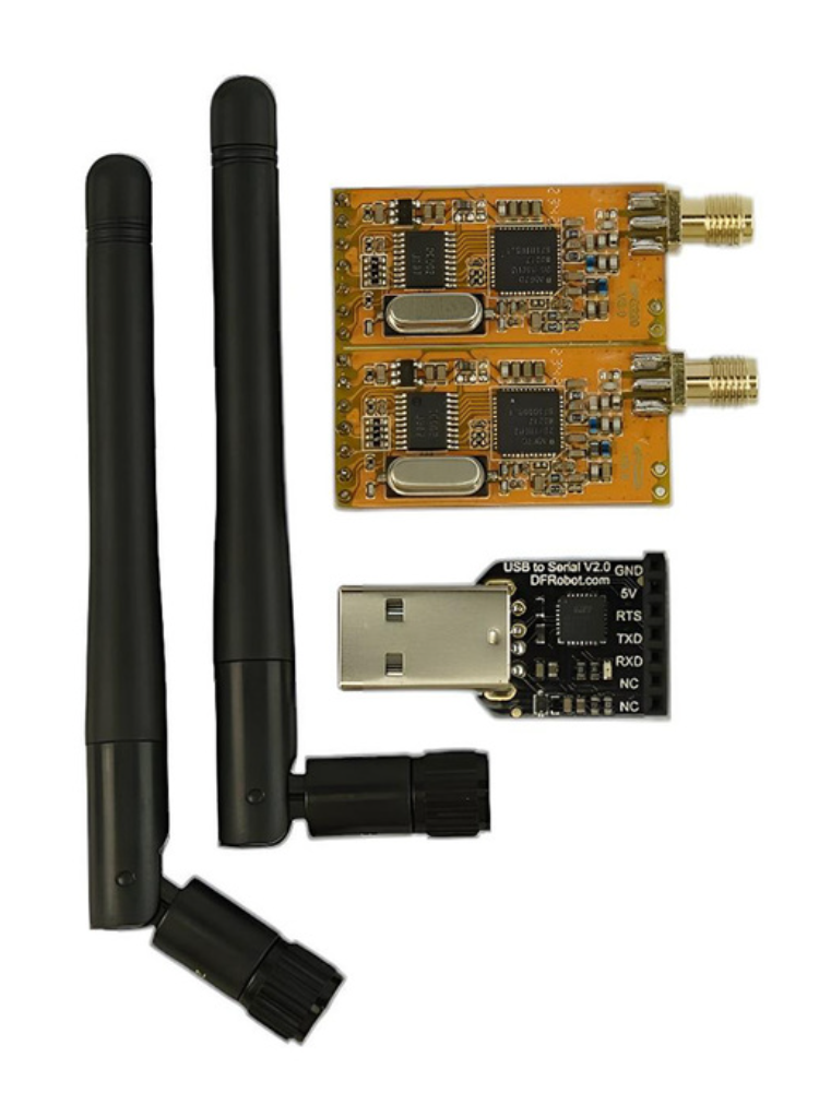
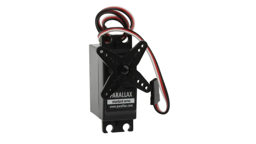
Types of Common RC Servo Motors
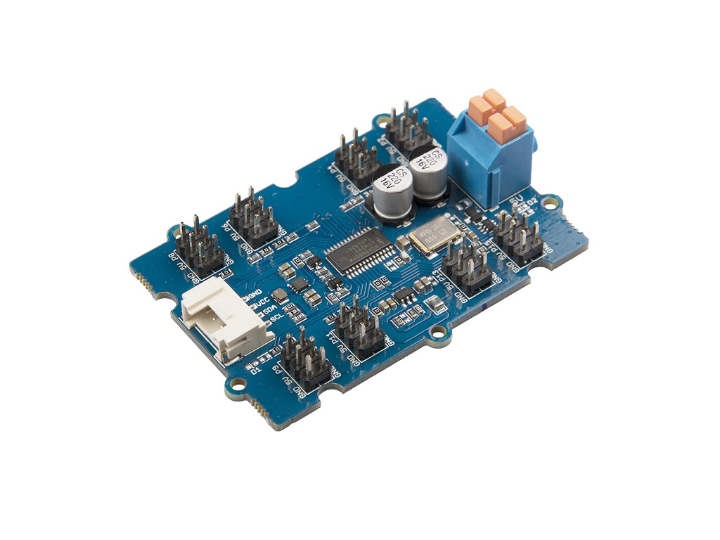
Using a PWM Driver
You may come across many online tutorials that show how to control servo motors directly without a PWM driver. While this method is possible, it’s not the most reliable—especially when working with multiple servos. Sooner or later, you’re likely to run into issues, often related to power management and signal stability.
For this reason, inIn this tutorial, we’llwe bewill usinguse two Arduino, one for sending (Leonardo) and one for receiving (UNO). For clarity, we use two different models, but you can use the Seeedsame Studiomodel 16-channelor PWM driver for more stable and scalable control. You can also useany other similar PWM driver boards depending on your needs.
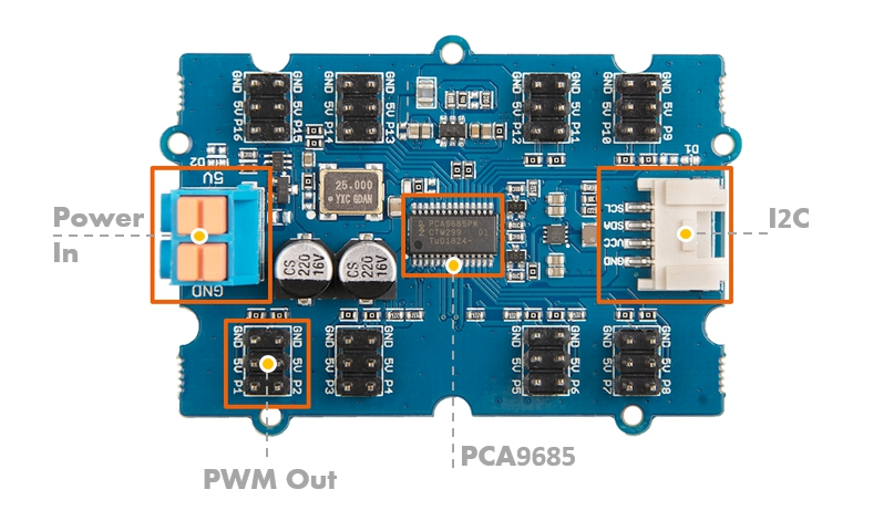
Wiring
-
5V Power Supply on the Left:+to 5V-to GND
i2C toArduinoonLeonardothe-Right:Sending:- GND to GND
5VVCC to 5VSCLTXD toSCL8SDARXD toSDA9
-
ServoArduinotoUNOPWM-Out:Receiving:Plug in the servo, where the black wire goesGND totheGND- VCC to 5V
- TXD to 8
- RXD to 9
GND
Library
OnlyUse
Grove-16-Channel_PWM_Driver-PCA9685 library will be used.
We have a tutorialSoftwareSerial on howboth Arduinos. Never directly connect APC220 RXD to installArduino aTX libraryif here.they use different logic levels (some APC220 modules are 3.3V-only).
Getting started
Arduino Leonardo - Regular ServoSending
This code is getting the eight servo motors to rotate to 0 degrees and then 90 degrees, one by one.
#include "PCA9685.h"
#include <Wire.SoftwareSerial.h>
ServoDriverSoftwareSerial servo;radio(8, 9); // RX, TX

void setup() {
  // join I2C bus (I2Cdev library doesn't do this automatically)
    Wire.begin();
    Serial.radio.begin(9600);
    servo.init(0x7f);
}

void loop() {
  //radio.println("Hello Drivefrom 8 servos in turns
    for (int i = 1; i < 9; i++Leonardo!")
    {
        servo.setAngle(i, 0);
        delay(1000);
        servo.setAngle(i, 90);
  delay(1000);
}
}
GettingArduino startedUNO - Continuous Servo
Since a continuous servo is controlled by a pulse, the ‘degree’ values work differently. Values like 0, 90, and 180 don’t represent angles; instead, they typically control rotation direction and speed — for example, 0 means full speed clockwise, 90 means stop, and 180 means full speed counterclockwise.
The below code is getting the servo motor 1 rotates clockwise for 1 second and stop for 1 second.
#include "PCA9685.h"
#include <Wire.SoftwareSerial.h>
ServoDriverSoftwareSerial servo;radio(8, 9); // RX, TX

void setup() {
  // join I2C bus (I2Cdev library doesn't do this automatically)
    Wire.begin();
    Serial.begin(9600);
  servo.init(0x7f);

    //Most continuous servo motors' pulse width is 900-2100
    servo.setServoPulseRange(900,2100,180)radio.begin(9600);
}

void loop() {
  //if Drive(radio.available()) 8{
    servosString inmsg turns= servo.setAngle(1, 0)radio.readStringUntil('\n');
    delay(1000)Serial.println("Received: " + msg);
  servo.setAngle(1, 90);
        delay(1000);}
}
Testing
- Open Serial Monitor on the UNO to see received messages,
Hello from Leonardo!. - Both radios must be powered on and within range.
- Ensure no serial baud mismatch.
- Do not connect APC220 to Arduino RX0/TX1 pins while uploading code—use SoftwareSerial instead.