Radio Communication: How to use RFM69HCW Radio Data Module
What is APC220RFM69HCW Radio Data Module?
The APC220 Radio Data ModuleRFM69HCW is a compact,high-performance, low-power,power wirelessradio transceiver module designed for seriallong-range wireless communication overusing longsub-GHz distancesfrequencies. usingUnlike simple UART-based modules like the 433APC220, MHzthe ISMRFM69HCW band.offers It’sSPI commonlycommunication, usedencryption, and packet-based transmission, making it highly suitable for Arduinomore projectscomplex and secure wireless sensor networks,networks.
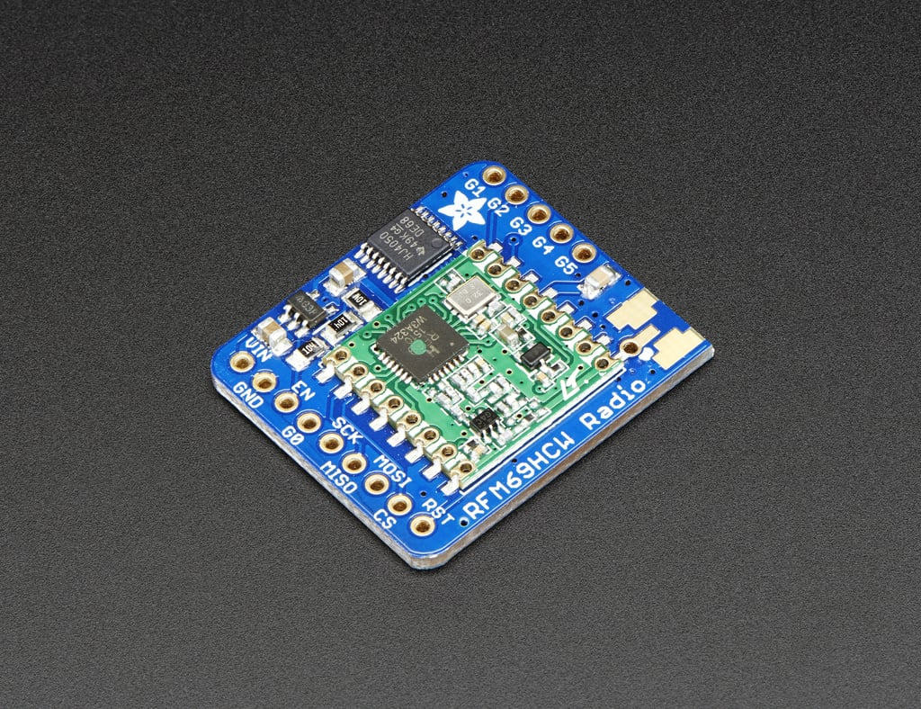
In this tutorial, we will usebe using two Arduino,Arduino UNO, one for sending (Leonardo) and one for receivingreceiving. (UNO).RFM69HCW Forcomes clarity,with different versions, we useare twousing differentthe models,433 butMHz youversion in this tutorial.
Differences from APC220
| Feature | APC220 | RFM69HCW |
|---|---|---|
| Communication Interface | UART (Serial) | SPI |
| Operating Frequency | 433 MHz | 433 / 868 / 915 MHz (depending on model) |
| Modulation Type | GFSK | FSK, GFSK, OOK |
| Communication Range | ~1000 m (line of sight) | 500 m – 1500+ m (configurable) |
| Data Rate | 1200 – 19200 bps | Up to 300 kbps |
| Encryption | ❌ Not supported | ✅ 128-bit AES encryption |
| Power Supply | 3.3V – 5V | 1.8V – 3.6V |
| Topology | Point-to-point | Point-to-point or mesh |
| Library Required | No (uses standard Serial) | Yes (RadioHead, RFM69, etc.) |
| Use Case Simplicity | Beginner-friendly | Requires more setup/code |
Wiring (same wiring for both)
3.3V Only
RFM69HCW runs on 3.3V — powering it from 5V can usepermanently thedamage same model or any other model.it.
Wiring
Arduino Leonardo - Sending:- GND to GND
VCCVIN to5V3.3VTXDSCK to8D13RXDMISO to9D12- MOSI to D11
- CS to D4
- RST to D2
- G0 (IRQ) to D3
Download
ArduinotheUNORadioHead-libraryReceiving:here.- We
GNDhave a tutorial on how toGNDinstall VCCatolibrary5VTXD to 8RXD to 9
Library
SoftwareSerial OnlyUse SoftwareSerial on both Arduinos. Never directly connect APC220 RXD to Arduino TX if they use different logic levels (some APC220 modules are 3.3V-only).here.
Getting started
Arduino Leonardo - Sending
This code is getting the eight servo motors to rotate to 0 degrees and then 90 degrees, one by one.
#include <SoftwareSerial.SPI.h>
SoftwareSerial#include radio(8,<RH_RF69.h>

9);/************ Radio Setup ***************/

// RX,Change TXto 434.0 or other frequency, must match RX's freq!
#define RF69_FREQ 434.0
#define RFM69_CS   4
#define RFM69_INT  3
#define RFM69_RST  2
#define LED        13


// Singleton instance of the radio driver
RH_RF69 rf69(RFM69_CS, RFM69_INT);

int16_t packetnum = 0;  // packet counter, we increment per xmission

void setup() {
  radio.Serial.begin(9600)115200);
  //while (!Serial) delay(1); // Wait for Serial Console (comment out line if no computer)

  pinMode(LED, OUTPUT);
  pinMode(RFM69_RST, OUTPUT);
  digitalWrite(RFM69_RST, LOW);

  Serial.println("RFM69 TX Test!");
  Serial.println();

  // manual reset
  digitalWrite(RFM69_RST, HIGH);
  delay(10);
  digitalWrite(RFM69_RST, LOW);
  delay(10);

  if (!rf69.init()) {
    Serial.println("RFM69 radio init failed");
    while (1);
  }
  Serial.println("RFM69 radio init OK!");
  // Defaults after init are 434.0MHz, modulation GFSK_Rb250Fd250, +13dbM (for low power module)
  // No encryption
  if (!rf69.setFrequency(RF69_FREQ)) {
    Serial.println("setFrequency failed");
  }

  // If you are using a high power RF69 eg RFM69HW, you *must* set a Tx power with the
  // ishighpowermodule flag set like this:
  rf69.setTxPower(20, true);  // range from 14-20 for power, 2nd arg must be true for 69HCW

  // The encryption key has to be the same as the one in the server
  uint8_t key[] = { 0x01, 0x02, 0x03, 0x04, 0x05, 0x06, 0x07, 0x08,
                    0x01, 0x02, 0x03, 0x04, 0x05, 0x06, 0x07, 0x08};
  rf69.setEncryptionKey(key);

  Serial.print("RFM69 radio @");  Serial.print((int)RF69_FREQ);  Serial.println(" MHz");
}

void loop() {
  radio.println(delay(1000);  // Wait 1 second between transmits, could also 'sleep' here!

  char radiopacket[20] = "Hello fromWorld Leonardo!#";
  itoa(packetnum++, radiopacket+13, 10);
  Serial.print("Sending "); Serial.println(radiopacket);

  // Send a message!
  rf69.send((uint8_t *)radiopacket, strlen(radiopacket));
  rf69.waitPacketSent();

  // Now wait for a reply
  uint8_t buf[RH_RF69_MAX_MESSAGE_LEN];
  uint8_t len = sizeof(buf);

  if (rf69.waitAvailableTimeout(500)) {
    // Should be a reply message for us now
    if (rf69.recv(buf, &len)) {
      Serial.print("Got a reply: ");
      Serial.println((char*)buf);
      Blink(LED, 50, 3); // blink LED 3 times, 50ms between blinks
    } else {
      Serial.println("Receive failed");
    }
  } else {
    Serial.println("No reply, is another RFM69 listening?");
  }
}

void Blink(byte pin, byte delay_ms, byte loops) {
  while (loops--) {
    digitalWrite(pin, HIGH);
    delay(1000)delay_ms);
    digitalWrite(pin, LOW);
    delay(delay_ms);
  }
}
Arduino UNO - Receiving
#include <SoftwareSerial.SPI.h>
SoftwareSerial#include radio(8,<RH_RF69.h>

9);/************ Radio Setup ***************/

#define RF69_FREQ 434.0
#define RFM69_CS   4
#define RFM69_INT  3
#define RFM69_RST  2
#define LED        13

// RX,Singleton TXinstance of the radio driver
RH_RF69 rf69(RFM69_CS, RFM69_INT);

void setup() {
  Serial.begin(9600)115200);
  radio.begin(9600)//while (!Serial) delay(1); // Wait for Serial Console (comment out line if no computer)

  pinMode(LED, OUTPUT);
  pinMode(RFM69_RST, OUTPUT);
  digitalWrite(RFM69_RST, LOW);

  Serial.println("RFM69 RX Test!");
  Serial.println();

  // manual reset
  digitalWrite(RFM69_RST, HIGH);
  delay(10);
  digitalWrite(RFM69_RST, LOW);
  delay(10);

  if (!rf69.init()) {
    Serial.println("RFM69 radio init failed");
    while (1);
  }
  Serial.println("RFM69 radio init OK!");

  // Defaults after init are 434.0MHz, modulation GFSK_Rb250Fd250, +13dbM (for low power module)
  // No encryption
  if (!rf69.setFrequency(RF69_FREQ)) {
    Serial.println("setFrequency failed");
  }

  // If you are using a high power RF69 eg RFM69HW, you *must* set a Tx power with the
  // ishighpowermodule flag set like this:
  rf69.setTxPower(20, true);  // range from 14-20 for power, 2nd arg must be true for 69HCW

  // The encryption key has to be the same as the one in the server
  uint8_t key[] = { 0x01, 0x02, 0x03, 0x04, 0x05, 0x06, 0x07, 0x08,
                    0x01, 0x02, 0x03, 0x04, 0x05, 0x06, 0x07, 0x08};
  rf69.setEncryptionKey(key);

  Serial.print("RFM69 radio @");  Serial.print((int)RF69_FREQ);  Serial.println(" MHz");
}

void loop() {
 if (radio.rf69.available()) {
    String// msgShould be a message for us now
    uint8_t buf[RH_RF69_MAX_MESSAGE_LEN];
    uint8_t len = radio.readStringUntil('\n'sizeof(buf);
    if (rf69.recv(buf, &len)) {
      if (!len) return;
      buf[len] = 0;
      Serial.print("Received [");
      Serial.print(len);
      Serial.print("]: ");
      Serial.println((char*)buf);
      Serial.print("RSSI: ");
      Serial.println(rf69.lastRssi(), DEC);

      if (strstr((char *)buf, "Hello World")) {
        // Send a reply!
        uint8_t data[] = "And hello back to you";
        rf69.send(data, sizeof(data));
        rf69.waitPacketSent();
        Serial.println("Received:Sent a reply");
        Blink(LED, 40, 3); // blink LED 3 times, 40ms between blinks
      }
    } else {
      Serial.println("Receive +failed");
    msg)}
  }
}

void Blink(byte pin, byte delay_ms, byte loops) {
  while (loops--) {
    digitalWrite(pin, HIGH);
    delay(delay_ms);
    digitalWrite(pin, LOW);
    delay(delay_ms);
  }
}
Testing
- Open Serial Monitor on the UNO to see received messages,
Hello from Leonardo!. - Both radios must be powered on and within range.
- Ensure no serial baud mismatch.
- Do not connect APC220 to Arduino RX0/TX1 pins while uploading code—use SoftwareSerial instead.