Using a Vibration motor
What is a virbation motor?
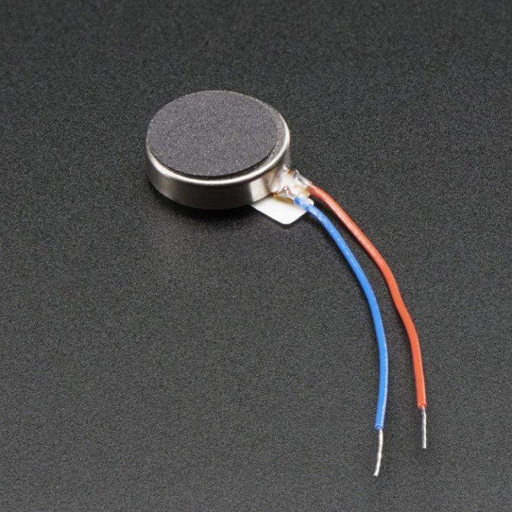
Vibration motor is a DC motor in a compact size that is used to inform the users by vibrating on receiving signals. The one that is available in the lab is coin vibration motor.
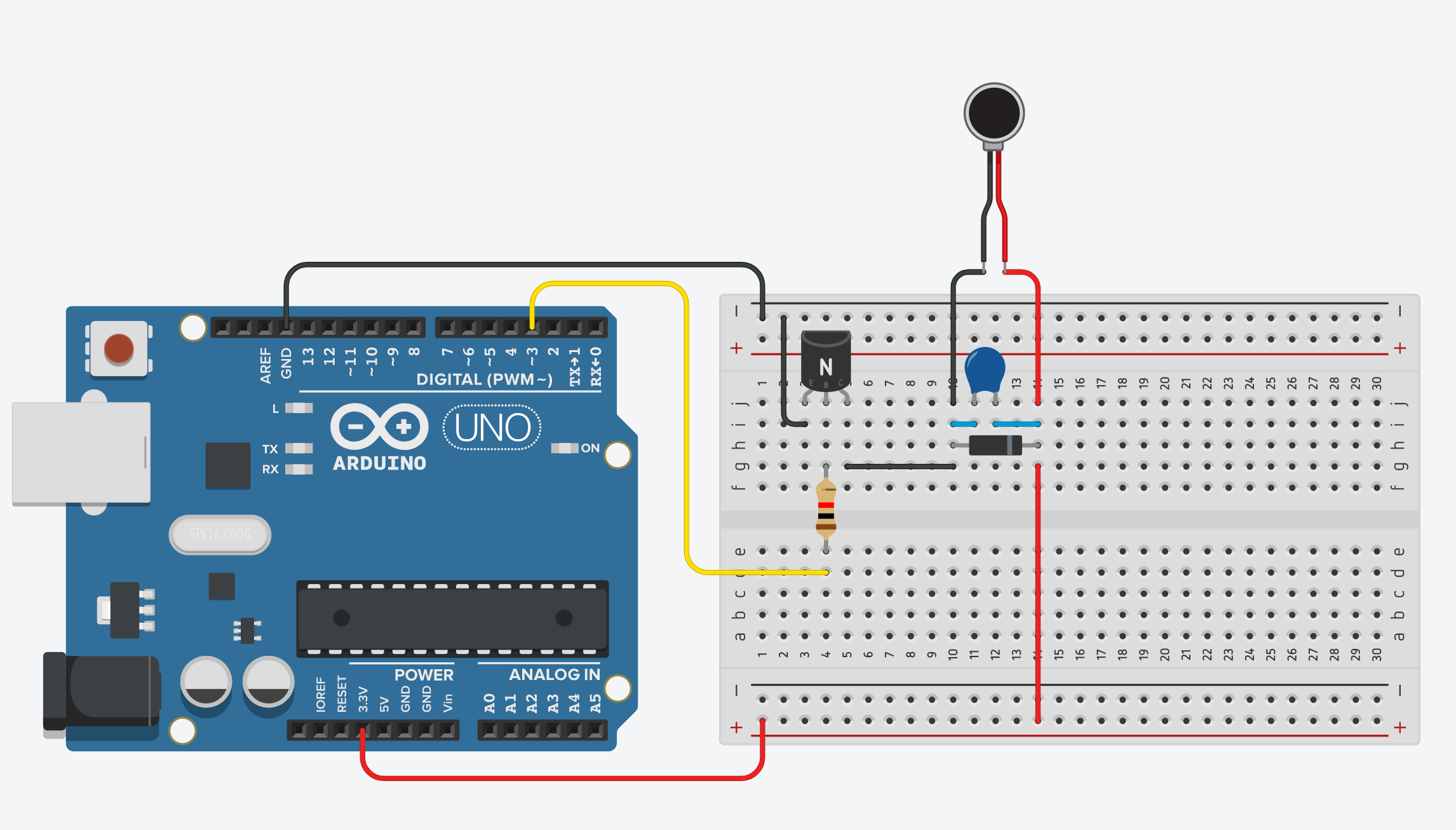
It requires more currnet than an Arduino pincan provide, so a transistor is needed to switch the motor current on and off. Any NPN transistor can be used. In this tutorial, we are using 2N2222. The diode acts as a surge protector against voltage spikes that the motor may produce. The 0.1µF capacitor absorbs voltage spikes produced when the brushes, which are contacts connecting electric current to the motor windings, open and close. To make sure that not too much current flow from the output of the transistor, we place a 1KΩ in series with the base of the transistor. Any value can be used up to 5KΩ.
Wiring
These are the electronics used in the circuit.
- vibration motor
- 2N2222 transistor
- 0.1µF capacitor
- 1N4001 diode
- 1KΩ resistor
It is a quite complex circuit but try your best to follow!
Getting started
int motorPin = 3; //motor transistor is connected to pin 3

void setup()
{
  pinMode(motorPin, OUTPUT);
}

void loop()
{
  digitalWrite(motorPin, HIGH); //vibrate
  delay(1000);  // delay one second
  digitalWrite(motorPin, LOW);  //stop vibrating
  delay(1000); //wait 50 seconds.
}