Using NEMA17 Stepper motor with Big Easy Driver
What is L293D?NEMA17 Stepper motor?
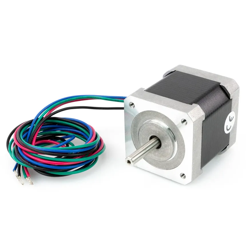
A NEMA 17 stepper motor is a compact, precise motor commonly used in 3D printers, CNC machines, and robotics. “NEMA 17” refers to its 1.7 × 1.7 inch mounting face size, while the stepper design allows it to move in fixed steps (typically 200 per revolution), making it ideal for accurate position control without feedback sensors.
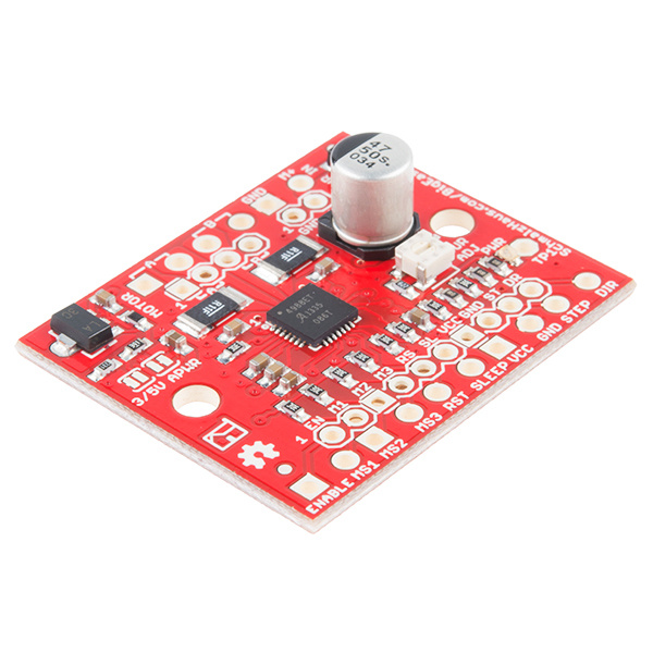
What is Big Easy Driver?
The L293DBig Easy Driver is a 16-pinstepper Motormotor Driverdriver ICboard whichbased canon the A4988 chip, used to control astepper setmotors like NEMA 17 with microcontrollers such as Arduino. It allows easy control of twomotor DCspeed, motorsdirection, simultaneouslyand inmicrostepping anywhile direction.handling Thehigher L293Dcurrent issafely designedand toefficiently. provideKnow bidirectional drive currents of up to 600 mA (per channel) at voltages from 4.5 V to 36 V. It can be extremely hot. When they get overheated, they may not follow commands anymore.More
It is cheap but may not have the easiest pinout to read for beginners.
DC motor
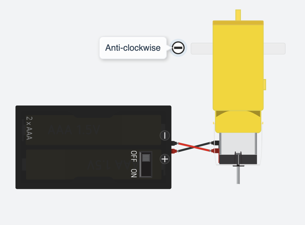
DC motor is very common to be found in toys. It usually comes with 2 wires, one red(+) and one black(-).
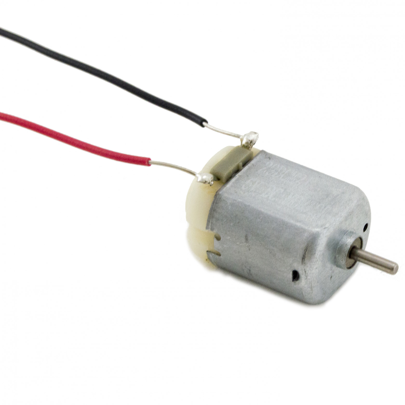
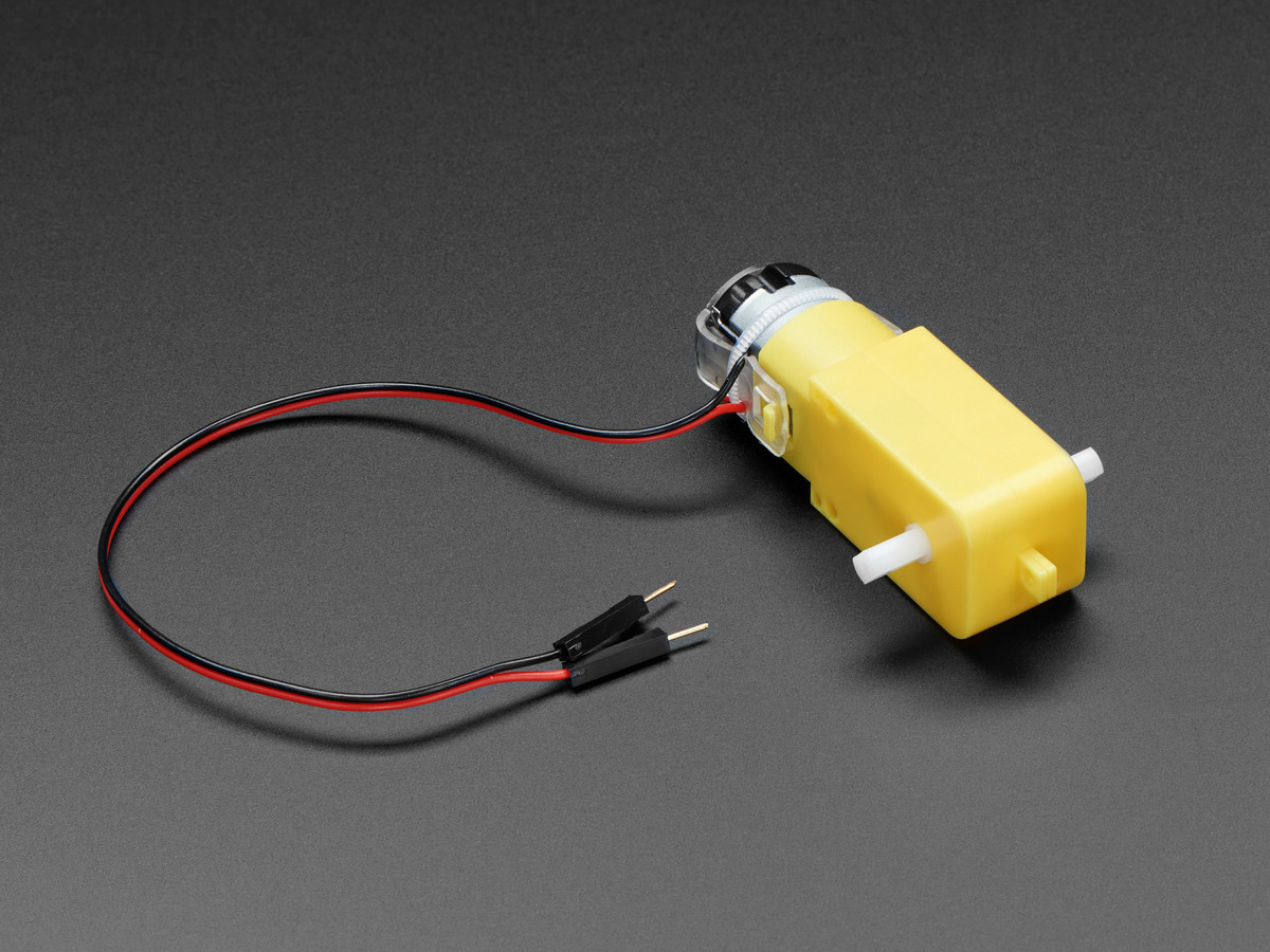
Although it can be small and cheap, it can be very fast. Therefore sometimes it comes with a gearbox which will slow down the speed of the motor.
Taking a 12V DC motor for example, we connect the red wire of the motor to the positive wire of the power supply and the black wire of the motor to the negative wire of the power supply as normal practice. We will get a motor running clockwise at full speed.
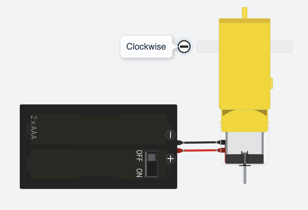
BUT if we reverse the red and black wires of the motor we connect the black wire of the motor to the positive wire of the power supply and the red wire of the motor to the negative wire of the power supply. We will get a motor running anti-clockwise at full speed.
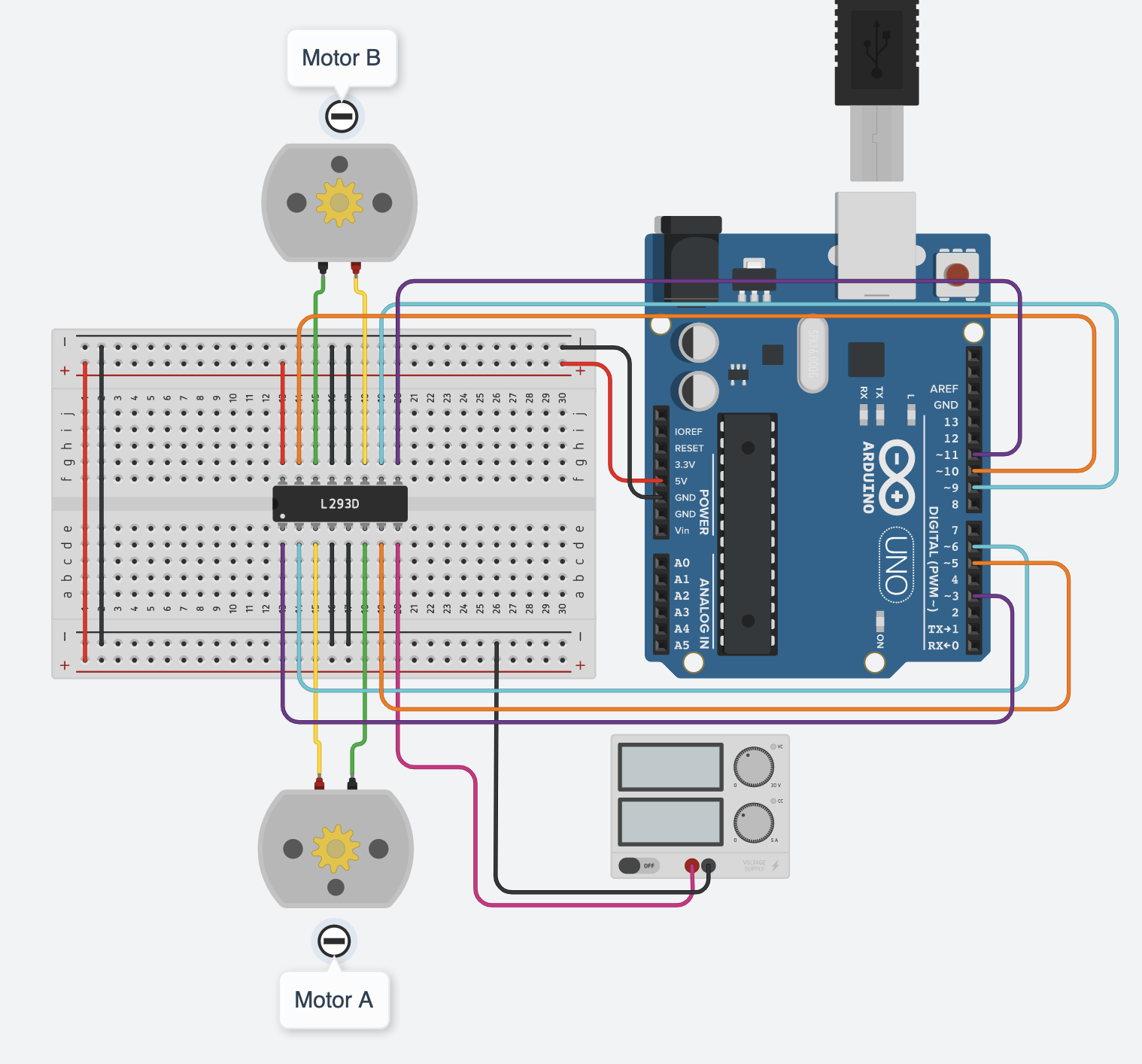
Wiring
BeBefore careful with which pin on the IC to which pin on the Arduino as there are 16 pinswiring, you need to connect!
Pinout of L293D
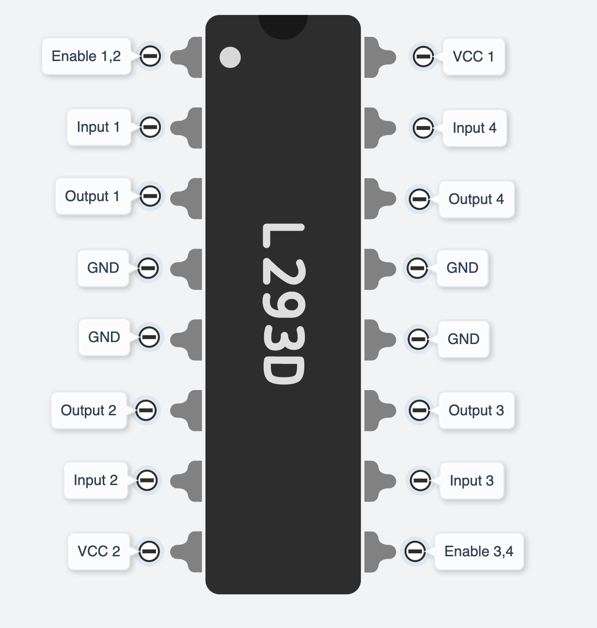
You may not understand what these labels stand for. Let's look atout the below one, you can see where they are actually connected to and what they do.
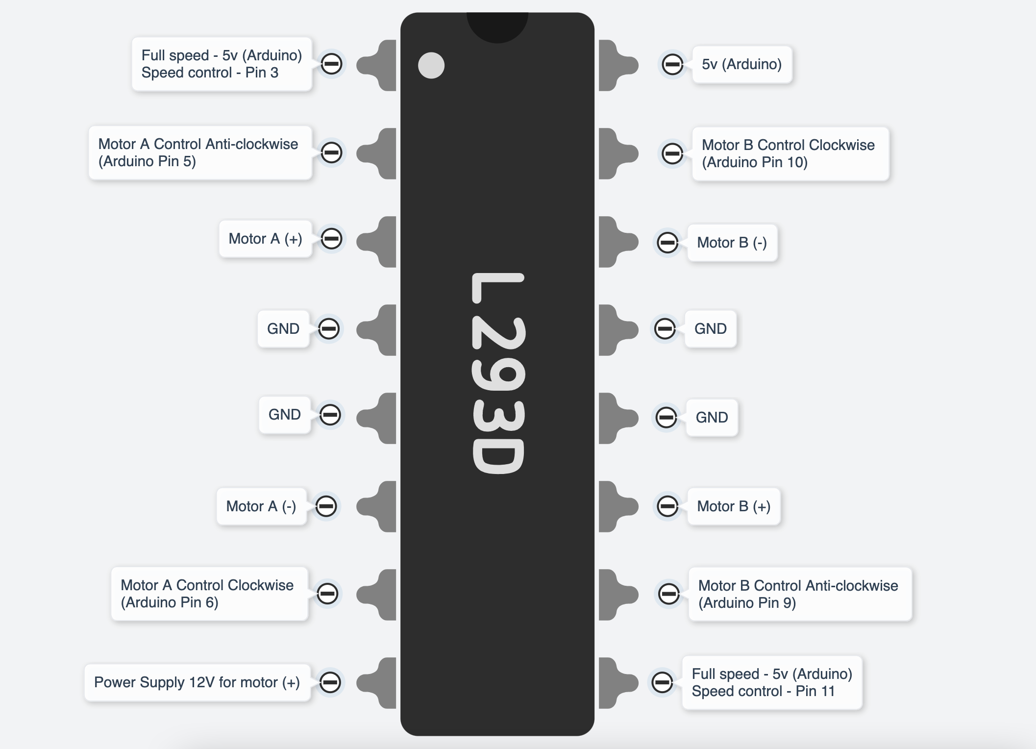
As said earlier, the DC motor changes direction by reversing the + wire and - wire. If you reverse Motor A (+) (Pin3 of IC) and Motor A (-)(Pin6 of IC), the Pin2 of IC (Arduino Pin 5) will be the Clockwise control and the Pin7 of IC (Arduino Pin 6) will be the Anti-clockwise control.
You do not have to strictly follow which digital pins on Arduino
to be used, as long as you match the number of pins in the code.
And you will need to use PWM(~) pinspairs for botheach speed control pinscoil on the ICmotor (ICyou pin1plan &to 9).use. You can usually find this information from the datasheet. In this tutorial, we are using a 4-wire NEMA17 motor with no polarity on the coil.
Uno → Big Easy Driver
- D2 → STEP
- D3 → DIR
- D4 → MS1
- D5 → MS2
- D6 → MS3
- D7 → ENABLE
- GND → GND
Motor → Big Easy Driver
- Black → A
- Green → A
- Red → B
- Blue → B
- 12V power + → M+
- 12V power - → GND
Get started
This example code willdemonstrates let4 youmodes: testforward, thereverse, directions of the motorsmicrostep and hasalternate custom functions for forward(), backward(), stop(), turnRight() and turnLeft().directions.
//L293DDeclare pin functions on Arduino
#define stp 2
#define dir 3
#define MS1 4
#define MS2 5
#define MS3 6
#define EN  7

//MotorDeclare Avariables constfor functions
char user_input;
int motorAspeed  = 3;
constx;
int motorPin1  = 5;  // Pin 14 of L293
consty;
int motorPin2  = 6;  // Pin 10 of L293
//Motor B
const int motorBspeed  = 11;
const int motorPin3  = 10; // Pin  7 of L293
const int motorPin4  = 9;  // Pin  2 of L293

//This will run only one time.state;

void setup() {
  pinMode(stp, OUTPUT);
  pinMode(dir, OUTPUT);
  pinMode(MS1, OUTPUT);
  pinMode(MS2, OUTPUT);
  pinMode(MS3, OUTPUT);
  pinMode(EN, OUTPUT);

  resetBEDPins(); //Set step, direction, microstep and enable pins asto outputsdefault pinMode(motorPin1,states
  OUTPUT);
    pinMode(motorPin2, OUTPUT);
    pinMode(motorPin3, OUTPUT);
    pinMode(motorPin4, OUTPUT);
    pinMode(motorAspeed, OUTPUT);
    pinMode(motorBspeed, OUTPUT);


    analogWrite(motorAspeed, 255)Serial.begin(9600); //setOpen Serial connection for debugging
  Serial.println("Begin motor Acontrol");

speed}

0-255//Main analogWrite(motorBspeed,loop
255)void loop() {


  StepForwardDefault();
  ReverseStepDefault();
  SmallStepMode();
  ForwardBackwardStep();


}

//Reset Easy Driver pins to default states
void resetBEDPins()
{
  digitalWrite(stp, LOW);
  digitalWrite(dir, LOW);
  digitalWrite(MS1, LOW);
  digitalWrite(MS2, LOW);
  digitalWrite(EN, HIGH);
}

//Default microstep mode function
void StepForwardDefault()
{
  Serial.println("Moving forward at default step mode.");
  digitalWrite(EN, LOW); //Pull enable pin low to set FETs active and allow motor Bcontrol
  speeddigitalWrite(dir, 0-255
  /*LOW); //MotorPull Controldirection Testingpin -low Motorto A:move motorPin1,motorpin2"forward"
  &for(x= Motor0; B:x<1000; motorpin3,motorpin4x++)  //ThisLoop codethe willforward turnstepping Motorenough A clockwisetimes for 2motion sec.to be visible
  {
    digitalWrite(motorPin1,stp,HIGH); //Trigger one step forward
    delay(1);
    digitalWrite(stp,LOW); //Pull step pin low so it can be triggered again
    delay(1);
  }
  resetBEDPins();
}

//Reverse default microstep mode function
void ReverseStepDefault()
{

  Serial.println("Moving in reverse at default step mode.");
  digitalWrite(EN, LOW); //Pull enable pin low to set FETs active and allow motor control
  digitalWrite(dir, HIGH); //5Pull direction pin high to move in "reverse"
  for(x= 0; x<1000; x++)  //Loop the stepping enough times for motion to be visible
  {
    digitalWrite(motorPin2,stp,HIGH); //Trigger one step
    delay(1);
    digitalWrite(stp,LOW); //Pull step pin low so it can be triggered again
    delay(1);
  }
  resetBEDPins();
}

// 1/16th microstep foward mode function
void SmallStepMode()
{
  Serial.println("Stepping at 1/16th microstep mode.");
  digitalWrite(EN, LOW); //Pull enable pin low to set FETs active and allow motor control
  digitalWrite(motorPin3,dir, LOW); digitalWrite(motorPin4, LOW);
    delay(2000);
    //ThisPull codedirection willpin turnlow Motorto Amove counter-clockwise for 2 sec."forward"
  digitalWrite(motorPin1, LOW);
    digitalWrite(motorPin2,MS1, HIGH); //6Pull MS1,MS2, and MS3 high to set logic to 1/16th microstep resolution
  digitalWrite(motorPin3,MS2, LOW)HIGH);
  digitalWrite(motorPin4,MS3, LOW)HIGH);
  delay(2000);for(x= 0; x<1000; x++)  //ThisLoop codethe willforward turnstepping Motorenough B clockwisetimes for 2motion sec.to be visible
  {
    digitalWrite(motorPin1, LOW);
    digitalWrite(motorPin2, LOW);
    digitalWrite(motorPin3, stp,HIGH); //10Trigger one step forward
    delay(1);
    digitalWrite(motorPin4,stp,LOW); //Pull step pin low so it can be triggered again
    delay(1);
  }

  resetBEDPins();
}
//Forward/reverse stepping function
void ForwardBackwardStep()
{
  Serial.println("Alternate between stepping forward and reverse.");
  digitalWrite(EN, LOW); delay(2000);//Pull enable pin low to set FETs active and allow motor control
  for(x= 1; x<5; x++)  //ThisLoop codethe willforward turnstepping Motorenough B counter-clockwisetimes for 2motion sec.to digitalWrite(motorPin1,be LOW);visible
  digitalWrite(motorPin2, LOW);
    digitalWrite(motorPin3, LOW);
    digitalWrite(motorPin4, HIGH);{
    //9Read delay(2000)direction pin state and change it
    state=digitalRead(dir);
    //Andif(state this== codeHIGH)
    will stop motors
    digitalWrite(motorPin1, LOW);
    digitalWrite(motorPin2, LOW);
    digitalWrite(motorPin3, LOW);
    digitalWrite(motorPin4, LOW);
  */
}


void loop(){

  forward();
  delay(5000);

  backward();
  delay(5000);

  stop();
  delay(5000);

  turnRight();
  delay(5000);

  turnLeft();
  delay(5000);
}

void forward(){
      digitalWrite(motorPin1, HIGH);
  digitalWrite(motorPin2, LOW);
  digitalWrite(motorPin3, HIGH);
  digitalWrite(motorPin4,dir, LOW);
    }
    voidelse backward()if(state ==LOW)
    {
      digitalWrite(motorPin1, LOW);
  digitalWrite(motorPin2, HIGH);
  digitalWrite(motorPin3, LOW);
  digitalWrite(motorPin4, dir,HIGH);
    }

    voidfor(y=0; stop(y<1000; y++)
    {
      digitalWrite(motorPin1,stp,HIGH); //Trigger one step
      delay(1);
      digitalWrite(stp,LOW); digitalWrite(motorPin2,//Pull LOW);step digitalWrite(motorPin3,pin LOW);low digitalWrite(motorPin4,so LOW)it can be triggered again
      delay(1);
    }
  void turnRight(){
  digitalWrite(motorPin1, HIGH);
  digitalWrite(motorPin2, LOW);
  digitalWrite(motorPin3, LOW);
  digitalWrite(motorPin4, LOW);
}
  void turnLeft(resetBEDPins(){
  digitalWrite(motorPin1, LOW);
  digitalWrite(motorPin2, LOW);
  digitalWrite(motorPin3, HIGH);
  digitalWrite(motorPin4, LOW);
}
There is a simulated circuit made in Tinkercad for you to try out!