How to make Animation on NeoMatrix with Processing
WhatControlling isNeoMatrix NeoMatrix?with Processing
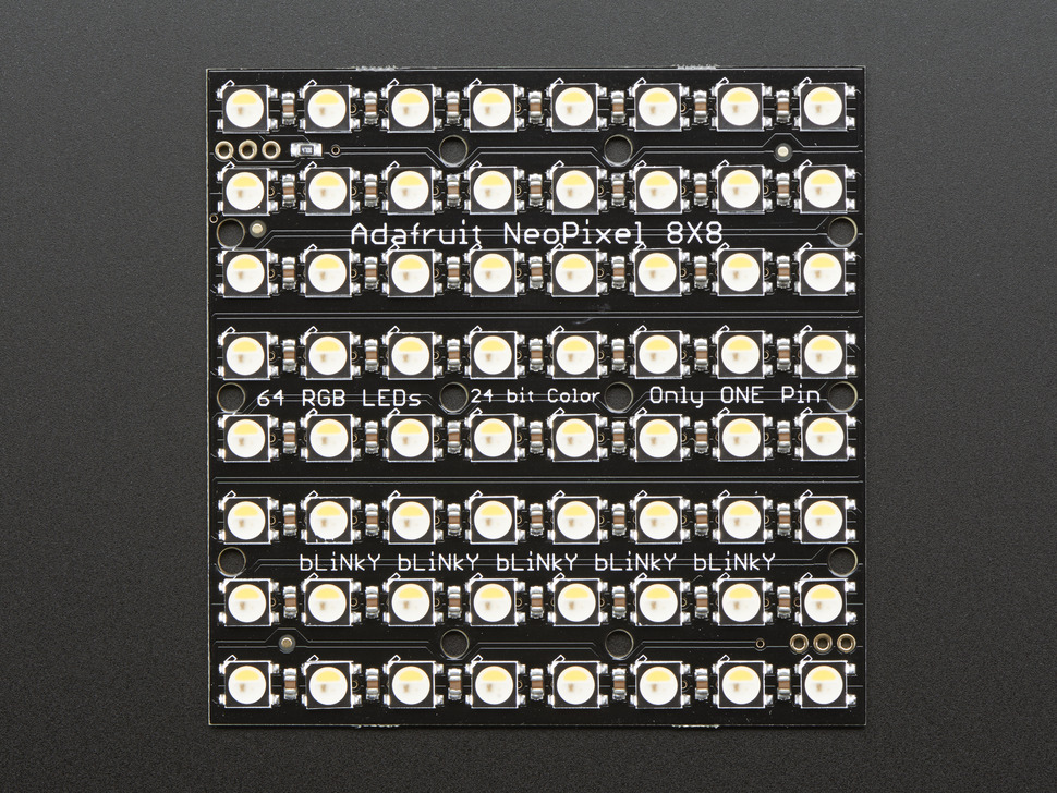
NeoMatrixThis tutorial is a grid lined follow-up with mutiple Neopixel. Neopixel is addressable LEDs, meaning that they can be programmed individually. Withto the librarylast createdNeoMatrix by Adafruit, you can easily program the Neopixel strip for your project. They come in different sizes and shapes and you can shorten or lengthen them flexibly. Once set up, they are very durable and efficient. They are commonly found in a lot house decorations or light installations.We have aanimation tutorial. about Neopixel here.
In this tutorial, weWe are using aProcessing to create images, videos or realtime interaction and push those to an 8x8 NeoMatrixAdafruit from Adafruit.NeoMatrix.
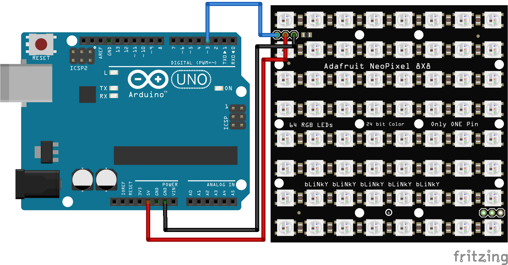
Wiring
Warning
If you have a bigger matrix, you will need an extra power supply. The extra power supply will share the ground with Arduino and the matrix.
- DIN to Pin3
- +5V to 5V
- GND to GND
Library
Warning
Download version 1.9.0 or below of Adafruit Neopixel library for a more stable performance.
We will need three libraries for this tutorial.
We have a tutorial on how to install a library here.
GettingUnderstand startedyour Matrix
When programming the matrix, it is important to know the configuration of your matrix so that the x and y coordinates sent from Processing can be matched. The most important two are the starting point and the arrangement.
The Starting Point
the starting point: Usually it will be the Top Left. If you are building your own Matrix from scratch, it will be easier to program later if you choose the top left corner as your first pixel as 0,0 in Processing is the top left corner by default.
![]()
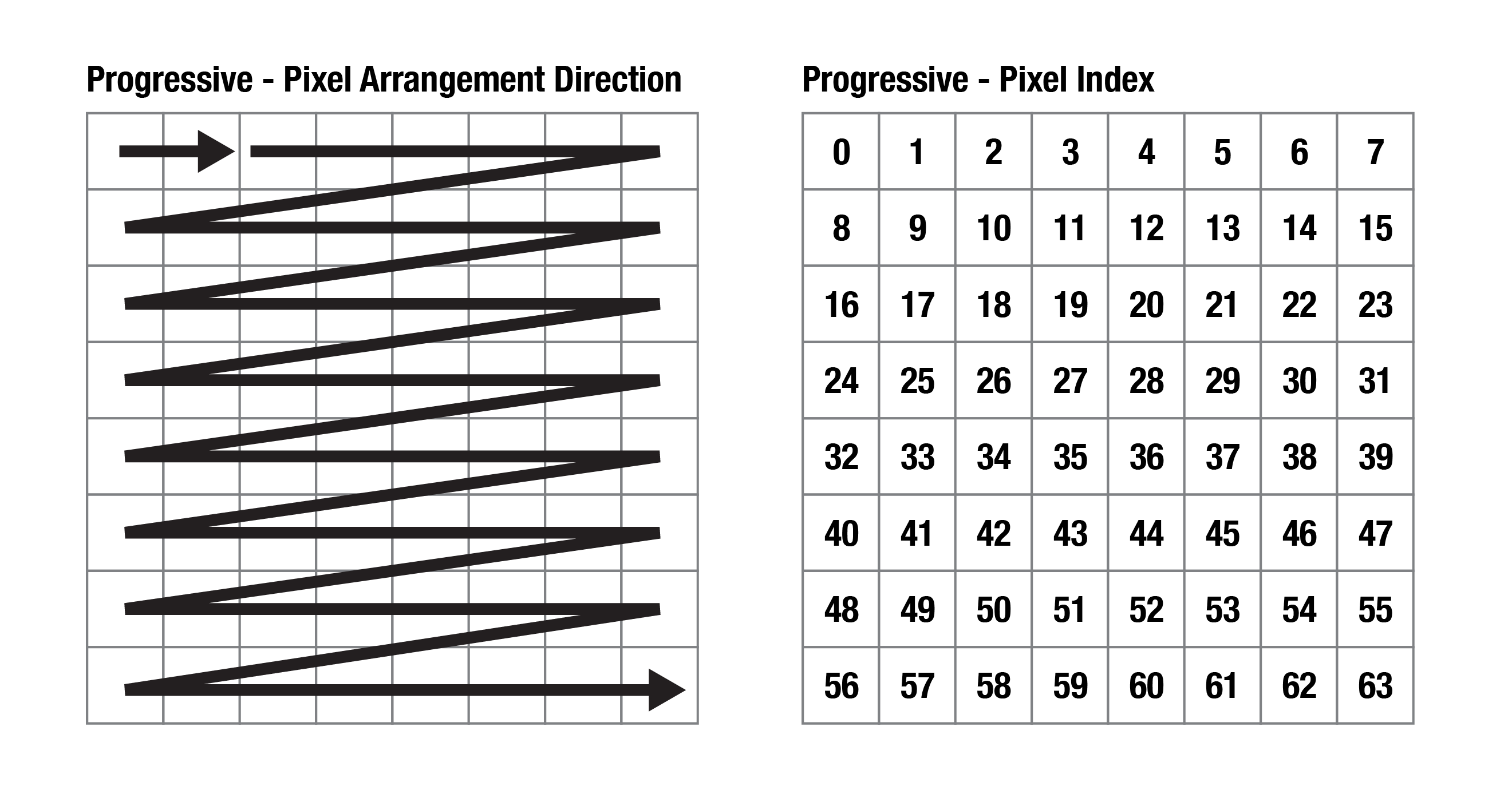
The Arrangement
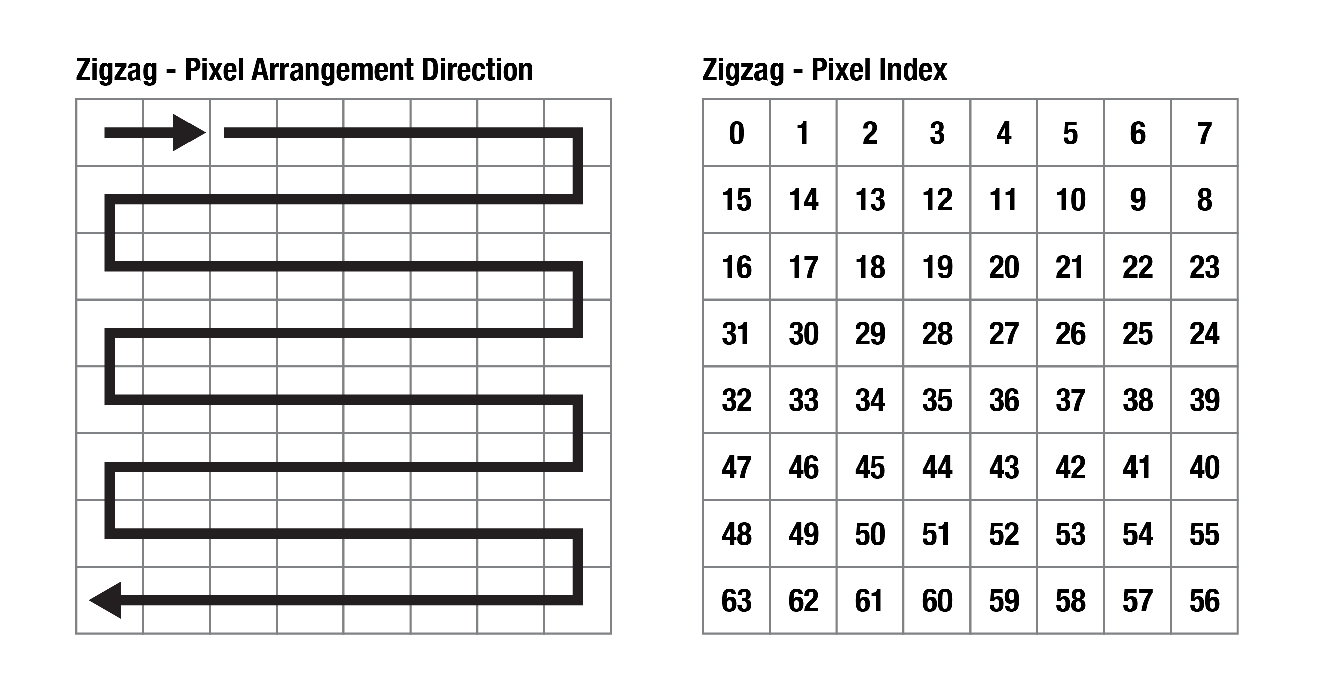
There are two types, Progressive and Zigzag.
Progressive: Adafruit's pre-built matrix is using this arrangement. It will make coding easier as the pixel index in Processing will be exactly the same as the pixel number on the Matrix. You don't have to alternate numbers for even-numbered rows.
Zigzag: It will be a more popular choice of arrangement for building a matrix from scratch as it involves shorter connections and it is easier for soldering.
If you have a second-hand matrix and are not sure about its configuration, you can run the strandtest code to see how the lights light up one by one.
Processing Code
We have a tutorial about serial communication between Processing and Arduino so I will skip it here. In this example code, you can draw with your mouse on the screen and the matrix will light up accordingly.
Before setup(), you will need to change the values of cols, rows, pixelSize and size(cols*pixelSize , rows*pixelSize); to fit your own project. Please read the comments in the code to see what they represent.
You can put the content that you wish to push to the matrix between loadPixels(); and updatePixels();.
loadPixels(); loads the pixel data of the current display window into the pixels[] array. The pixels[] array contains the colour values for all the pixels in the display window.
updatePixels(); is only necessary if the display has changed, e.g. video, interactive/generative graphic.
Learn more about images and pixels in Processing here.
import processing.serial.*;

Serial arduino;
int cols = 8; // Number of NeoPixel matrix columns
int rows = 8; // Number of NeoPixel matrix rows
int totalLEDs = cols * rows;
int pixelSize = 50; // Adjust this based on your webcam's resolution
int i = 0;
int blue = 0;

void setup() {
  size(400, 400); // size(cols*pixelSize , rows*pixelSize);
  background(0);

  // Set up serial communication with Arduino
  printArray(Serial.list());
  arduino = new Serial(this, Serial.list()[1], 115200); // Change baud rate if needed

}

void draw() {

//clear
  if (keyPressed == true) {
    background(0);
  }

  loadPixels(); //load pixel for neomatrix


    int x = i % cols;
    int y = i / cols;
    int loc = x + y * width/pixelSize;
    int cloc = (x*pixelSize + pixelSize/2) + y*pixelSize * width;
    color c = pixels[cloc];

    int r = (c >> 16) & 0xFF;
    int g = (c >> 8) & 0xFF;
    int b = c & 0xFF;
    //println(i);

    arduino.write(loc); //for progressive arrangement
    //arduino.write(x); //for zigzag arrangement
    //arduino.write(y); //for zigzag arrangement
    arduino.write(r);
    arduino.write(g);
    arduino.write(b);

    delay(10); // Small delay for stability
     i++;
      if (i >= totalLEDs){
    i = 0;
    }

  updatePixels();
}

void mouseDragged() {
  noStroke();
  fill(0,125,blue, 50);
  ellipse(mouseX,mouseY,pixelSize, pixelSize);
  blue ++;
  if (blue >= 255){
  blue = 0;
  }
}
Arduino Code
The examplefollowing shows the upward arrow first and then the animation of a colour-changing pattern. The upward arrowcode is for identifyingan 8x8 Adafruit NeoMatrix with the orientationbelow ofconfigurations.
- the starting point: Top Left
- the arrangement: Progressive
#include <Adafruit_GFX.h>
#include <Adafruit_NeoMatrix.h>
#include <Adafruit_NeoPixel.h>

int w = 8; //width Whichof pinmatrix
onint theh Arduino= is8; connected//height toof the NeoPixels?matrix
#define PIN            3 // MaxPin is 255, 32 is a conservative valueconnected to notthe overloadNeoPixels
#define NUMPIXELS       w*h // aNumber USBof power supplyNeoPixels (500mA)16x16 formatrix)

12x12Adafruit_NeoPixel pixels.
#define BRIGHTNESS 50

// Define matrix width and height.
#define mw 8
#define mh 8

#define LED_BLACK    0

int counterstrip = 0;
int numImage = 0;

// When we setup the NeoPixel library, we tell it how many pixels, and which pin to use to send signals.
// Note that for older NeoPixel strips you might need to change the third parameter--see the strandtest
// example for more information on possible values.
Adafruit_NeoMatrix *matrix = new Adafruit_NeoMatrix(mw, mh,Adafruit_NeoPixel(NUMPIXELS, PIN,
    NEO_MATRIX_TOP     + NEO_MATRIX_LEFT +
    NEO_MATRIX_ROWS + NEO_MATRIX_ZIGZAG, NEO_GRB + NEO_KHZ800);

static const uint16_t PROGMEM
// These bitmaps were written for a backend that only supported
// 4 bits per color with Blue/Green/Red ordering while neomatrix
// uses native 565 color mapping as RGB.
// I'm leaving the arrays as is because it's easier to read
// which color is what when separated on a 4bit boundary
// The demo code will modify the arrays at runtime to be compatible
// with the neomatrix color ordering and bit depth.


RGB_bmp[][64] = {


//up for identifying direction
{
0x000,  0x000,  0x000,  0x5C9,  0x5C9,  0x000,  0x000,  0x000,
0x000,  0x000,  0x5C9,  0x5C9,  0x5C9,  0x5C9,  0x000,  0x000,
0x000,  0x5C9,  0x000,  0x5C9,  0x5C9,  0x000,  0x5C9,  0x000,
0x5C9,  0x000,  0x000,  0x5C9,  0x5C9,  0x000,  0x000,  0x5C9,
0x000,  0x000,  0x000,  0x5C9,  0x5C9,  0x000,  0x000,  0x000,
0x000,  0x000,  0x000,  0x5C9,  0x5C9,  0x000,  0x000,  0x000,
0x000,  0x000,  0x000,  0x5C9,  0x5C9,  0x000,  0x000,  0x000,
0x000,  0x000,  0x000,  0x5C9,  0x5C9,  0x000,  0x000,  0x000,

},

//pattern1
{
0x72E,  0x000,  0x823,  0x823,  0x823,  0x823,  0x000,  0x72E,
0x000,  0x823,  0xEC5,  0xCDB,  0xCDB,  0xEC5,  0x823,  0x000,
0x823,  0xEC5,  0xCDB,  0x0FF,  0x0FF,  0xCDB,  0xEC5,  0x823,
0x823,  0xCDB,  0x0FF,  0x72E,  0x72E,  0x0FF,  0xCDB,  0x823,
0x823,  0xCDB,  0x0FF,  0x72E,  0x72E,  0x0FF,  0xCDB,  0x823,
0x823,  0xEC5,  0xCDB,  0x0FF,  0x0FF,  0xCDB,  0xEC5,  0x823,
0x000,  0x823,  0xEC5,  0xCDB,  0xCDB,  0xEC5,  0x823,  0x000,
0x72E,  0x000,  0x823,  0x823,  0x823,  0x823,  0x000,  0x72E,

},


//pattern2
{

0x823,  0x000,  0xEC5,  0xEC5,  0xEC5,  0xEC5,  0x000,  0x823,
0x000,  0xEC5,  0xCDB,  0x0FF,  0x0FF,  0xCDB,  0xEC5,  0x000,
0xEC5,  0xCDB,  0x0FF,  0x72E,  0x72E,  0x0FF,  0xCDB,  0xEC5,
0xEC5,  0x0FF,  0x72E,  0x823,  0x823,  0x72E,  0x0FF,  0xEC5,
0xEC5,  0x0FF,  0x72E,  0x823,  0x823,  0x72E,  0x0FF,  0xEC5,
0xEC5,  0xCDB,  0x0FF,  0x72E,  0x72E,  0x0FF,  0xCDB,  0xEC5,
0x000,  0xEC5,  0xCDB,  0x0FF,  0x0FF,  0xCDB,  0xEC5,  0x000,
0x823,  0x000,  0xEC5,  0xEC5,  0xEC5,  0xEC5,  0x000,  0x823,

},
//pattern3
{

0xEC5,  0x000,  0xCDB,  0xCDB,  0xCDB,  0xCDB,  0x000,  0xEC5,
0x000,  0xCDB,  0x0FF,  0x72E,  0x72E,  0x0FF,  0xCDB,  0x000,
0xCDB,  0x0FF,  0x72E,  0x823,  0x823,  0x72E,  0x0FF,  0xCDB,
0xCDB,  0x72E,  0x823,  0xEC5,  0xEC5,  0x823,  0x72E,  0xCDB,
0xCDB,  0x72E,  0x823,  0xEC5,  0xEC5,  0x823,  0x72E,  0xCDB,
0xCDB,  0x0FF,  0x72E,  0x823,  0x823,  0x72E,  0x0FF,  0xCDB,
0x000,  0xCDB,  0x0FF,  0x72E,  0x72E,  0x0FF,  0xCDB,  0x000,
0xEC5,  0x000,  0xCDB,  0xCDB,  0xCDB,  0xCDB,  0x000,  0xEC5,

},


//pattern4
{
0xCDB,  0x000,  0x0FF,  0x0FF,  0x0FF,  0x0FF,  0x000,  0xCDB,
0x000,  0x0FF,  0x72E,  0x823,  0x823,  0x72E,  0x0FF,  0x000,
0x0FF,  0x72E,  0x823,  0xEC5,  0xEC5,  0x823,  0x72E,  0x0FF,
0x0FF,  0x823,  0xEC5,  0xCDB,  0xCDB,  0xEC5,  0x823,  0x0FF,
0x0FF,  0x823,  0xEC5,  0xCDB,  0xCDB,  0xEC5,  0x823,  0x0FF,
0x0FF,  0x72E,  0x823,  0xEC5,  0xEC5,  0x823,  0x72E,  0x0FF,
0x000,  0x0FF,  0x72E,  0x823,  0x823,  0x72E,  0x0FF,  0x000,
0xCDB,  0x000,  0x0FF,  0x0FF,  0x0FF,  0x0FF,  0x000,  0xCDB,


},

//pattern5
{
0x0FF,  0x000,  0x72E,  0x72E,  0x72E,  0x72E,  0x000,  0x0FF,
0x000,  0x72E,  0x823,  0xEC5,  0xEC5,  0x823,  0x72E,  0x000,
0x72E,  0x823,  0xEC5,  0xCDB,  0xCDB,  0xEC5,  0x823,  0x72E,
0x72E,  0xEC5,  0xCDB,  0x0FF,  0x0FF,  0xCDB,  0xEC5,  0x72E,
0x72E,  0xEC5,  0xCDB,  0x0FF,  0x0FF,  0xCDB,  0xEC5,  0x72E,
0x72E,  0x823,  0xEC5,  0xCDB,  0xCDB,  0xEC5,  0x823,  0x72E,
0x000,  0x72E,  0x823,  0xEC5,  0xEC5,  0x823,  0x72E,  0x000,
0x0FF,  0x000,  0x72E,  0x72E,  0x72E,  0x72E,  0x000,  0x0FF,


},

};


void display_rgbBitmap(uint8_t bmp_num) {
  static uint16_t bmx, bmy;

  fixdrawRGBBitmap(bmx, bmy, RGB_bmp[bmp_num], 8, 8);
  bmx += 8;
  if (bmx >= mw) bmx = 0;
  if (!bmx) bmy += 8;
  if (bmy >= mh) bmy = 0;
  matrix->show();
}

// Convert a BGR 4/4/4 bitmap to RGB 5/6/5 used by Adafruit_GFX
void fixdrawRGBBitmap(int16_t x, int16_t y, const uint16_t *bitmap, int16_t w, int16_t h) {
  uint16_t RGB_bmp_fixed[w * h];
  for (uint16_t pixel = 0; pixel < w * h; pixel++) {
    uint8_t r, g, b;
    uint16_t color = pgm_read_word(bitmap + pixel);

    //Serial.print(color, HEX);
    b = (color & 0xF00) >> 8;
    g = (color & 0x0F0) >> 4;
    r = color & 0x00F;
    //Serial.print(" ");
    //Serial.print(b);
    //Serial.print("/");
    //Serial.print(g);
    //Serial.print("/");
    //Serial.print(r);
    //Serial.print(" -> ");
    // expand from 4/4/4 bits per color to 5/6/5
    b = map(b, 0, 15, 0, 31);
    g = map(g, 0, 15, 0, 63);
    r = map(r, 0, 15, 0, 31);
    //Serial.print(r);
    //Serial.print("/");
    //Serial.print(g);
    //Serial.print("/");
    //Serial.print(b);
    RGB_bmp_fixed[pixel] = (r << 11) + (g << 5) + b;
   // Serial.print(" -> ");
    //Serial.print(pixel);
    //Serial.print(" -> ");
    //Serial.println(RGB_bmp_fixed[pixel], HEX);
  }
  matrix->drawRGBBitmap(x, y, RGB_bmp_fixed, w, h);
}

void setup() {
  Serial.begin(115200);

  matrix->strip.begin();
  matrix->setTextWrap(false);
  matrix->setBrightness(BRIGHTNESS);
  // Test full bright of all LEDs. If brightness is too high
  // for your current limit (i.e. USB), decrease it.
  //matrix->fillScreen(LED_WHITE_HIGH);
  //matrix->strip.show(); //delay(1000) Initialize all pixels to 'off'
 strip.setBrightness(5); matrix->clear()//I set a super low brightness as it's easier for my eyes during prototyping.
  Serial.begin(115200); numImage=(sizeof(RGB_bmp) // sizeof(RGB_bmp[0]));Set Serial.print("Numberthe ofbaud images:rate ");to Serial.println(numImage);match Processing
}

void loop() {

//------------------------for clearprogressive thearrangement screen after X bitmaps have been displayed and we
  // loop back to the top left corner
  // 8x8 => 1, 16x8 => 2, 17x9 => 6
  static uint8_t pixmap_count = ((mw + 7) / 8) * ((mh + 7) / 8);
  // Cycle through red, green, blue, display 2 checkered patterns
  // useful to debug some screen types and alignment.

  Serial.print("Screen pixmap capacity: ");
  Serial.println(pixmap_count);

  display_rgbBitmap(counter++);
  delay(500);

  if (counter >=numImage){
    counter = 0;
  }

  Serial.println ("----------------------------------
  if (Serial.available() >= 4) { // Ensure complete location & RGB data received

    int loc = Serial.read();
    int r = Serial.read();
    int g = Serial.read();
    int b = Serial.read();
//------------------------for progressive arrangement ------------------------------"----

/*
//------------------------for zigzag arrangement ----------------------------------
 if (Serial.available() >= 5) { // Ensure complete x,y coordinates & RGB data received

    int x = Serial.read();
    int y = Serial.read();
    int r = Serial.read();
    int g = Serial.read();
    int b = Serial.read();

    //delay(1000) Calculate pixel index based on zigzag layout (adjust the logic as needed)
    int loc;
    if (y % 2 == 0) {
      loc = y * w + x; // If even row, use regular indexing
    } else {
      loc = (y * w) + (w-1 - x); // If odd row, reverse indexing
    }

//------------------------for zigzag arrangement ----------------------------------
*/
    strip.setPixelColor(loc, strip.Color(r, g, b)); // Control NeoPixels using received RGB values
    strip.show(); // Display the updated NeoPixel colors
  }

}
Disadvantage for this Setup
YouWe shouldare seeonly your Neopixel displayingusing the animationbare frameminimum of components and Serial communication for sending data, so the matrix will not update everything all at once instantly. It will update and light up the pixels one by frameone rightwhich now.
Creating your own Animation
To create the animation, we have to convert your animation into HEX code frame by frame. We have an Excel file you can download to do that.
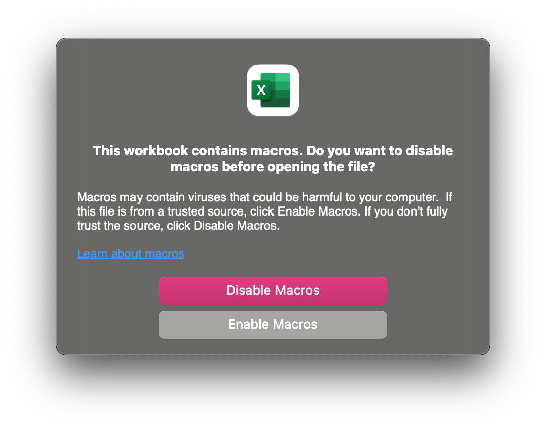
1. Enable Macros for Excel
2. Set up your Matrix
Type in the number of row and column (blue boxes) and then press Update Color_Pixel Page.
![]()
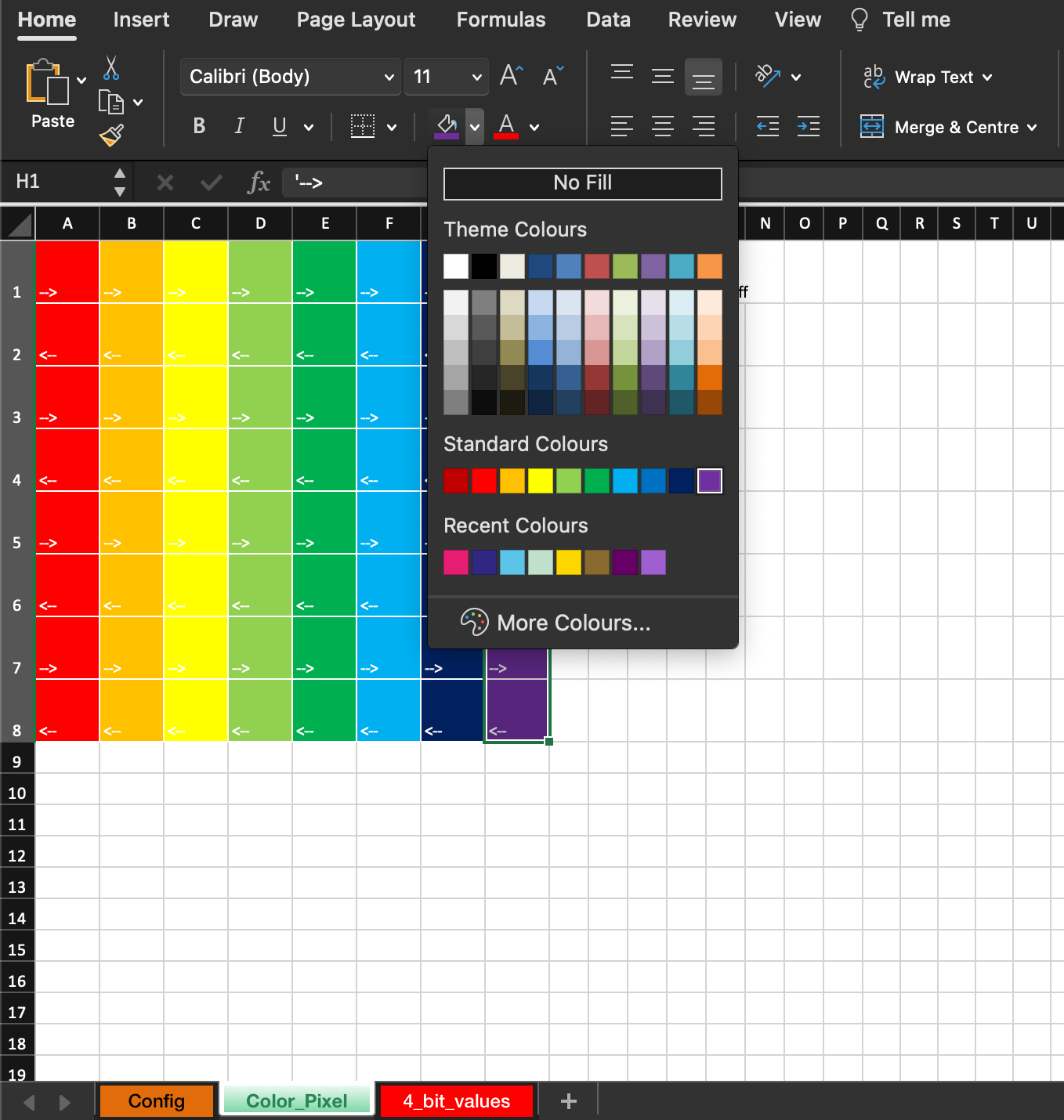
3. Create your Frame
Go to the Color_Pixel Tab, and start filling your Matrix with colours. Black means turning off that LED.
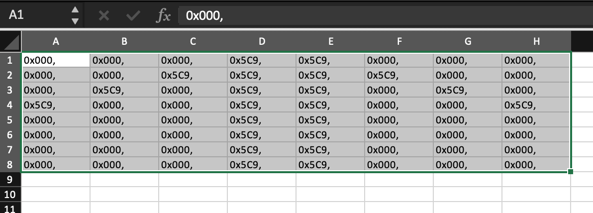
4. Convert your Frame to Code
When you are happy with your design, go to the Config Tab and press Update 4 Bit Values.

5. Copy your Code
Copy the Code in the 4_bit_values.
6. Paste your Code in Arduino IDE
The yellow highlighted part within {} will be the codefind to be replaced.quite Upload,artistic thenfor youmy are good to go!
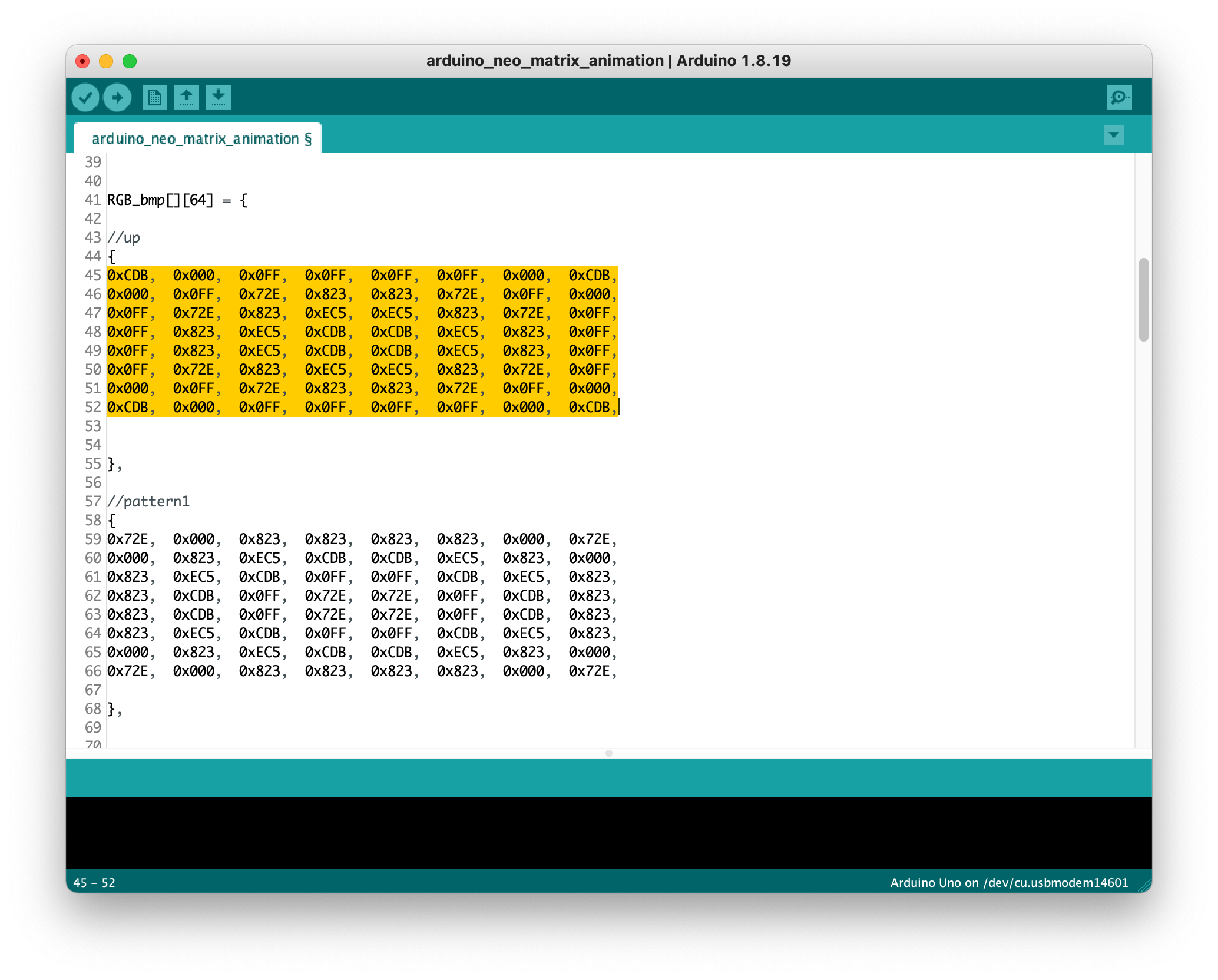
Have fun!