How to use a Rotary Encoder Button
What is a ServoRotary Motor?Encoder Button?
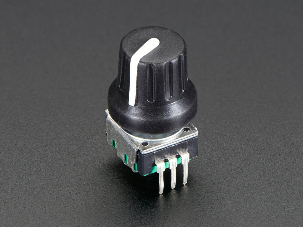
A servorotary motorencoder button is an input device that combines: a Rotary encoder — to detect rotational direction (clockwise/counterclockwise) and steps and a Push button — to detect when the knob is pressed down. This component is smaller in size and significantly cheaper than a regular rotary actuatorencoder.
This allowsrotary forencoder preciseis controluseful ofas angulara position,rotation velocity,sensor or selector and acceleration.looks Itsimilar isto commonlypotentiometers. usedThese inrotary robotics,encoders CNCrotate machinery,all conveyorthe belts,way around continuously and variousare automationdivided systems.up Ainto servo24 motor'segments'. worksEach bysegment receivinghas a controlclicky signalfeeling thatto represents a desired output position,it, and iteach usesmovement anclockwise internalor feedbackcounter-clockwise systemcauses the two switches to adjustopen theand motor’s movement accordingly. We often use RC (Radio-Controlled) Servo Motors in physical computing.close.
Types of Common RC Servo Motors
Using a PWM Driver
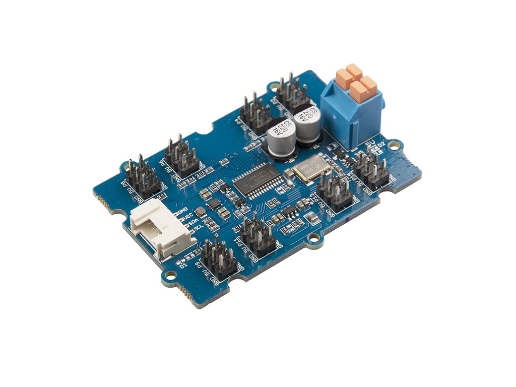
You may come across many online tutorials that show how to control servo motors directly without a PWM driver. While this method is possible, it’s not the most reliable—especially when working with multiple servos. Sooner or later, you’re likely to run into issues, often related to power management and signal stability.
For this reason, in this tutorial, we’ll be using the Seeed Studio 16-channel PWM driver for more stable and scalable control. You can also use other similar PWM driver boards depending on your needs.
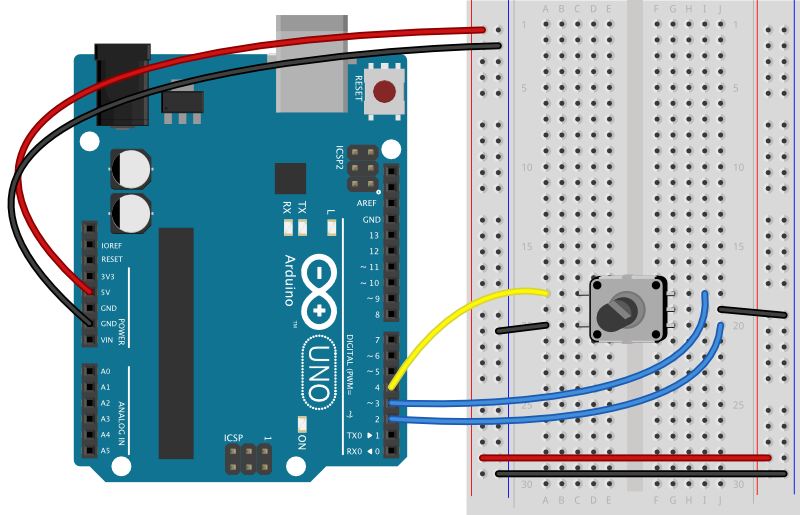
Wiring
-
5VTopPower2Supply on the Left:Pins:- one
+5VD4 - one
-
- one
-
i2CBottomto3Arduino on the Right:Pins:GNDRight Pin to D3- middle pin to GND
5VLeft Pin to5VSCL to SCLSDA to SDA
Servo to PWM Out:Plug in the servo, where the black wire goes to the GNDD2
Library
Grove-16-Channel_PWM_Driver-PCA9685EncoderStepCounter library will be used.
We have a tutorial on how to install a library here.
Getting started - Regular Servo
This code is getting the eight servo motors to rotate to 0 degrees and then 90 degrees, one by one.
#include "PCA9685.h"
#include <Wire.EncoderStepCounter.h>

ServoDriverconst servo;int pin1 = 2;
const int pin2 = 3;

// Create encoder instance:
EncoderStepCounter encoder(pin1, pin2);

// encoder previous position:
int oldPosition = 0;

const int buttonPin = 4;    // pushbutton pin
int lastButtonState = LOW;  // last button state
int debounceDelay = 5;      // debounce time for the button in ms


void setup() {
  // join I2C bus (I2Cdev library doesn't do this automatically)
    Wire.begin();
    Serial.begin(9600);
  servo.init(0x7f)// Initialize encoder
  encoder.begin();
  // Initialize interrupts
  attachInterrupt(digitalPinToInterrupt(pin1), interrupt, CHANGE);
  attachInterrupt(digitalPinToInterrupt(pin2), interrupt, CHANGE);
  // set the button pin as an input_pullup:
  pinMode(buttonPin, INPUT_PULLUP);
}

void loop() {
  // Driveif 8you're servosnot using interrupts, you need this in turnsthe forloop:
  (encoder.tick();

  // read encoder position:
  int iposition = 1;encoder.getPosition();
  i// <read 9;the i++)pushbutton:
  int buttonState = digitalRead(buttonPin);
  //  // if the button has changed:
  if (buttonState != lastButtonState) {
    servo.setAngle(i,// 0)debounce the button:
    delay(debounceDelay);
    delay(1000)// if button is pressed:
    if (buttonState == LOW) {
      Serial.print("you pressed on position: ");
      servo.setAngle(i, 90);
        delay(1000)Serial.println(position);
    }
  }
Gettingsave startedcurrent -button Continuousstate Servo
for Sincenext time through the loop:
lastButtonState = buttonState;
// reset the encoder after 24 steps:
if (position % 24 == 0) {
encoder.reset();
position = encoder.getPosition();
}
// if there's been a continuouschange, servoprint isit:
controlledif by(position a!= pulse,oldPosition) the{
‘degree’Serial.println(position);
valuesoldPosition work= differently.position;
Values}
like}
0,// 90,Call andtick 180on don’tevery representchange angles; instead, they typically control rotation direction and speed — for example, 0 means full speed clockwise, 90 means stop, and 180 means full speed counterclockwise.
The below code is getting the servo motor 1 rotates clockwise for 1 second and stop for 1 second.
#include "PCA9685.h"
#include <Wire.h>

ServoDriver servo;interrupt
void setup(interrupt() {
  // join I2C bus (I2Cdev library doesn't do this automatically)
    Wire.begin(encoder.tick();
    Serial.begin(9600);
    servo.init(0x7f);

    //Most continuous servo motors' pulse width is 900-2100
    servo.setServoPulseRange(900,2100,180);
}

void loop()
{
    // Drive 8 servos in turns
        servo.setAngle(1, 0);
        delay(1000);
        servo.setAngle(1, 90);
        delay(1000);
}