Position-based Tracking using a Webcam
Tracking the position of people or objects can be useful when creating interactive projection mapping projects. In TouchDesigner there are various methods to achieve this; This tutorial will introduce you to some common techniques to determine the position of an object. Let's dive in!
To begin, open the VideoDeviceIn TOP and select your DEVICE in the parameters window - you can read more about operators and the parameters window here. Connect this operator to a Null TOP and activate the Display option by clicking on the blue dot in your node, this will allow you to easily monitor any alterations to your original source.
Object Isolation
The first method focuses on isolating your object by combining various TOPs to eliminate its background. It's important to note that this process begins outside of TouchDesigner, during scene setup in real life; Ensure your background has a solid, contrasting colour to your object.
In Touchdesigner, right-click on the connection line to INSERT a node to your network, here select the Level TOP. This operator is useful to adjust the brightness and contrast of your image. Use the sliders available to create a strong contrast between your object and background. Next add a Threshold TOP and change the COMPARATOR to Greater, then alter the THRESHOLD value to adjust the intensity of this effect. At this point your object should be highlighted in white, while the rest of your image should be transparent.
Tracking
Now that we have isolated our object from it's background we want to look for the white pixels in the image, to determine it's location. To do that we first have to size down our input's resolution, this way we will have less data to analyse while keeping readings accurate. In your network, just before the Threshold TOP, add a Resolution TOP and in the sub-category "Common" select your OUPUT RESOLUTION to be Eighth.
Afterwards add a TopTo CHOP to your threshold and in the sub-category "Crop" select your CROP to be Full Image. This converts the pixels in our image into channels, containing RGBA informations.
Our aim is to determine the position of the coloured pixels, to do so we'll be turning our channels into a table. To your TopTo CHOP node add a ChopTo DAT, this will turn the information retained in our channels into a series of 0s, where the pixels are transparent, and 1s, where the pixels are coloured. You can check your process by covering your camera with your hand, now the table in ChopTo DAT should be showing mostly 1s.
Finally, we want to convert these 1s into X and Y co-ordinates within the image, which acts as our cartesian plane. Add a Constant CHOP and create two channels, let's name these X and Y.
Add an Execute DAT, this should not be connected to your network. Right-click on the node and select "Edit Contents in Textport", delete the current Python code and paste the following in. The comments, preceded by an hashtag, briefly explain the various sections of this script.
# Defining begining of execution
def onFrameStart(frame):
    if me.time.frame % 5 == 0:
        # Referencing operators in our network
        source = op('chopto1')
        output = op('constant1')

        # Initializing empty lists for rows and columns
        rows = []
        cols = []

        # Looping through the rows and columns of the 'chopto1' operator
        for x in range(source.numRows):
            for y in range(source.numCols):
                # Checking if the value at position (x, y) in 'chopto1' is equal to 1
                if source[x, y] == 1:
                    # If true, add the row and column indices to the respective lists
                    rows.append(x)
                    cols.append(y)

        # Calculating the center of the selected points
        centerx = (max(rows) - ((max(rows) - min(rows)) / 2)) / source.numRows
        centery = (max(cols) - ((max(cols) - min(cols)) / 2)) / source.numCols

        # Outputting new values to 'constant' operator
        output.par.value0 = centerx - 0.5
        output.par.value1 = centery - 0.5

        return
Close the textport and in the parameters window of Execute DAT, turn on the Frame Start to execute the above Python code at the start of every frame. Your object's x and y co-ordinates are now updated in real-time in the Constant CHOP.
You can now link these values to a TOP shape and composite this with your original webcam input to check out the tracking magic, read more about this process here.
Colour Tracking
If you're planning to track multiple objects within the same area, the object isolation method might not be ideal. Instead you can track by colour; To achieve this, make sure your objects are of contrasting colours, as well as your background.
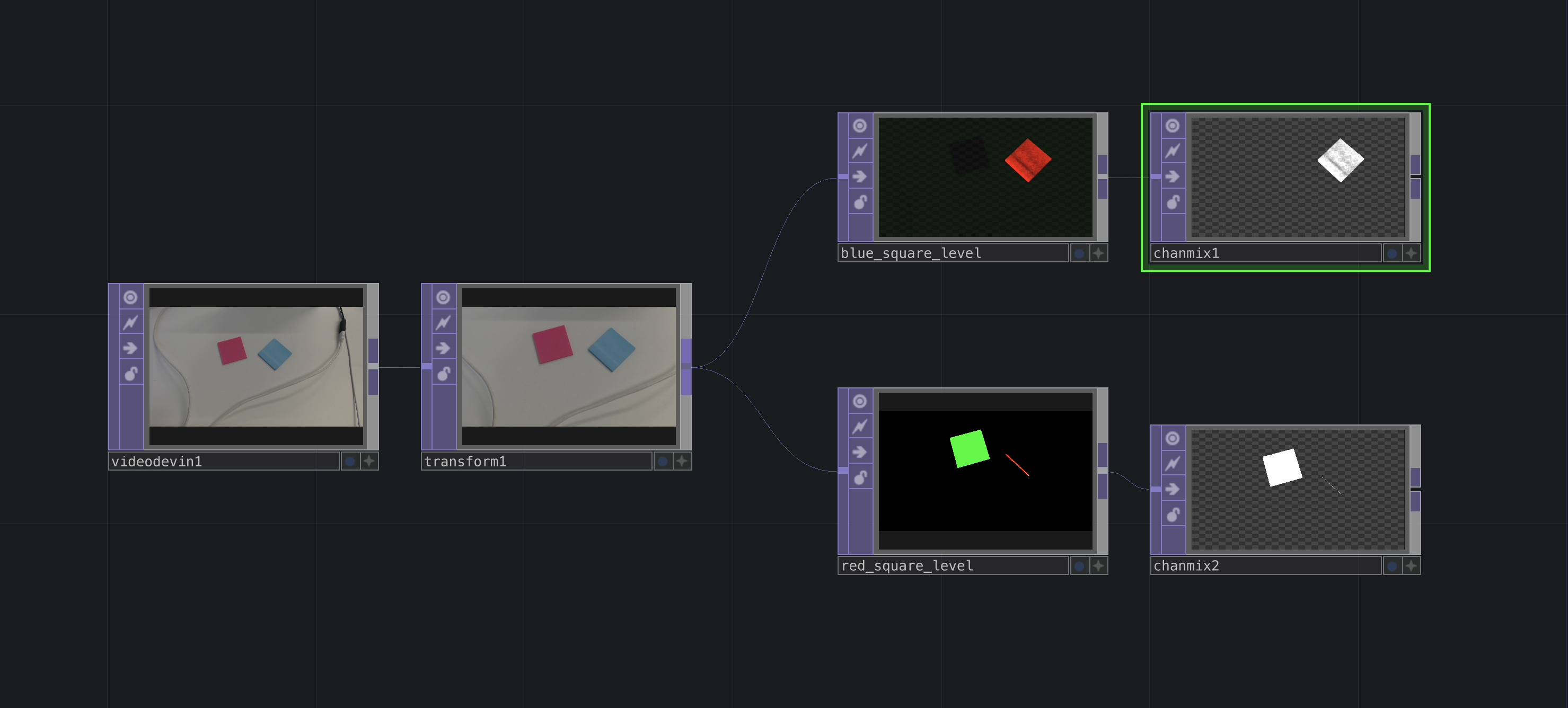
Our input will once again be our webcam in VideoDeviceIn TOP, this time we will connect to a Level TOP not only to adjust the brightness and contrast, within the sub-category "Pre", but to isolate a specific colour. Have a play with parameters in the sub-categories "Range" and "RGBA", the aim here is to make one colour prevail on all others.
Once your selected object is darker than all others, add a ChannelMix TOP to your network and change the RGBA values here to only display your object (values should be between 0 and 1). At this point your object should be the only item visible in the scene. From here we start tracking, refer to the section above.
Position-specific detection
If you wish to base your interaction on a specific position, you can use a Circle TOP to generate a placeholder. Assign it a specific colour, in my case I'll be using red, and Composite both your placeholder as well as your tracking shape using the Multiply method; This ensure that when the shape is right above the placeholder it will show up as red. Add an Analyze TOP and convert it into a CHOP to access a numerical trigger, use it to make a video start playing, to switch to another graphic, etc.
![]()