What are GPIO pins on Raspberry Pi?
What is GPIO?
GPIO stands for General-Purpose Input/Output. GPIOs have no predefined purpose and are unused by default. If used, the purpose and behaviour of a GPIO are defined and implemented by the user. You can find the GPIO pins on the top of most Raspberry Pi models or other microcontrollers such as Arduino.
GPIO pins are mostly used for connecting electronics with computers/microcontrollers. These components can then be programmed to perform different tasks using different languages, such as C++, Python and Scratch. In this tutorials, we will focus on the GPIO pins on Raspberry Pi.
Numbering of GPIO pins
GPIO pins on Raspberry Pi have two numbering systems, Board and Boardcom (BCM). For example, the board pin 8 and BCM pin 14 are referring the same pin. Numbering is important based on which programming languages and libraries you use.
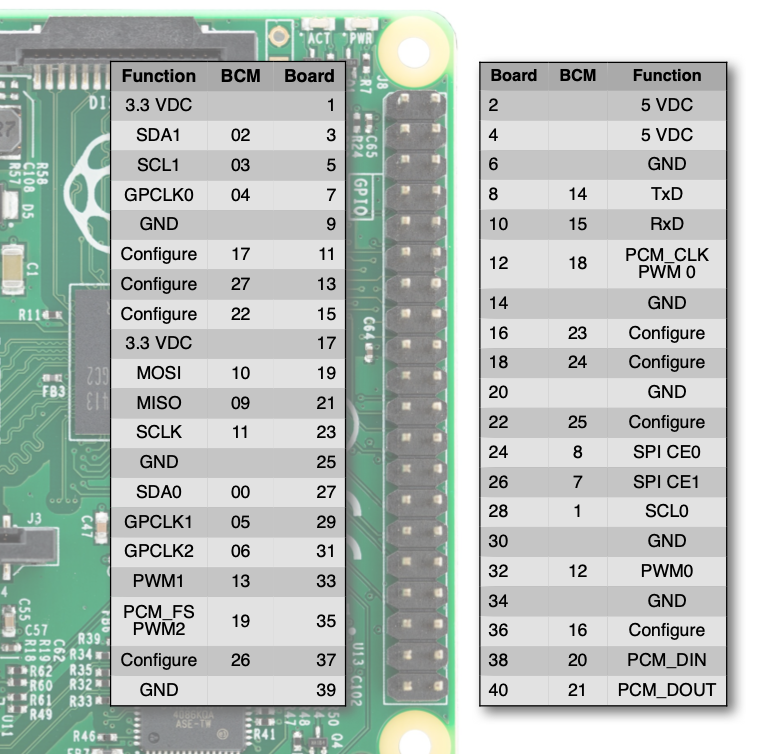
1. BCM numbering
BCM numbering matches up with the tiny labels printed on the Raspberry Pi, like GPIO14. It is used in most programming languages such as Python and Scratch.
2. Board numbering
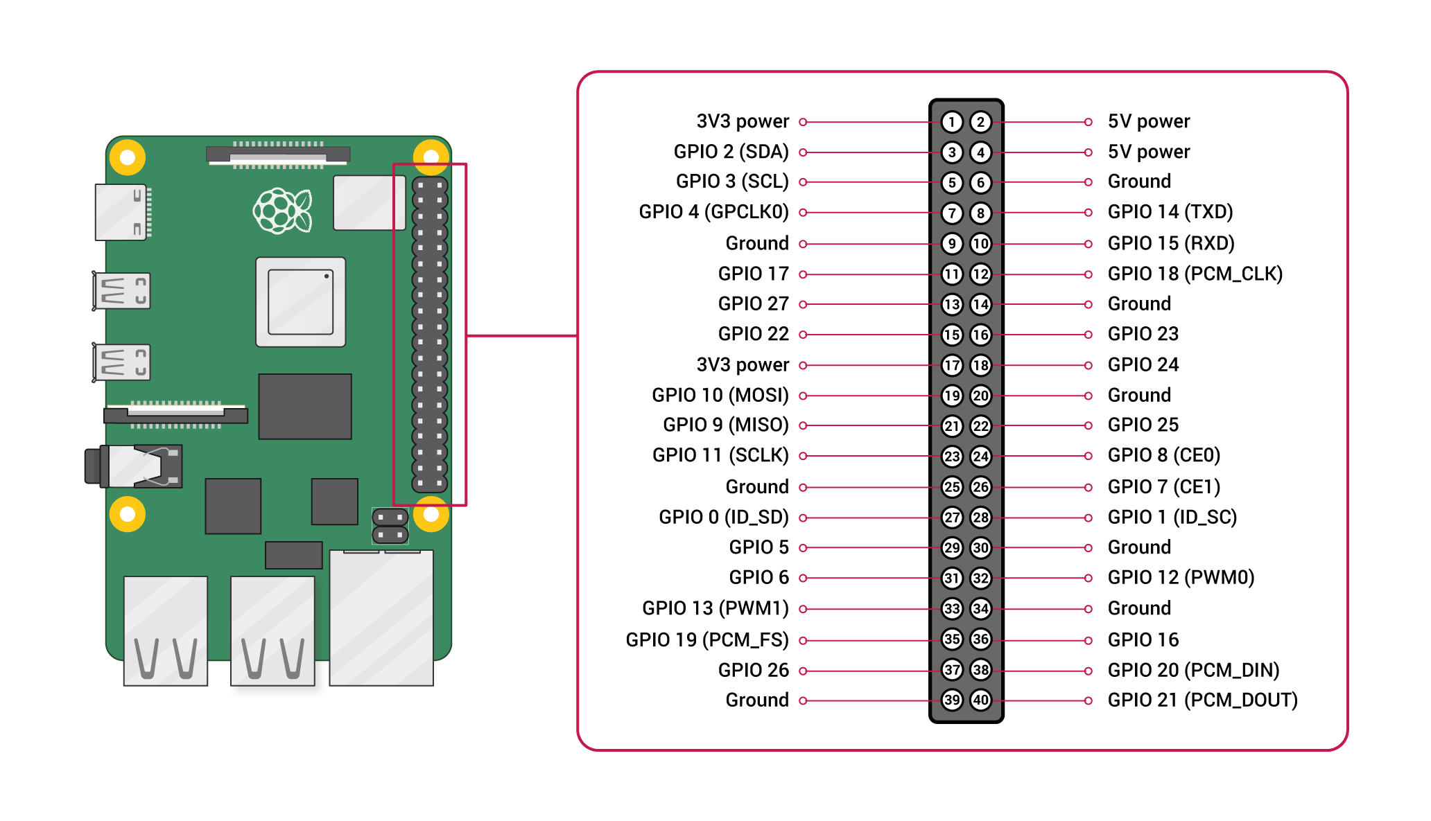
Board numbering is based on the physical locations of the pins on the Raspberry Pi. It starts from the top left corner as Pin 1, left to right then next line, and the bottom right will be the last pin, Pin 40. Board numbering is less common to be used, the only place you will see is probably in one or two Python libraries.
3. Functionalities of the Pins
Each pin on the pi has different functions and their physical locations may move from model to model. The pins without a BCM number are power output pins, such as GND and 5VDC. Pins with a BCM number are all PWM pins which can be used as input or output. Besides being a PWM pin, they also have other unique functions, such as GPIO 02 and GPIO 03 are also the pins of SDA and SCL for I²C communication. You can refer to the pinout of each model to find out more details of each pin.
Building Circuit with Raspberry Pi
UNPLUG your Pi when you are connecting electronics and DOUBLE CHECK your connections!Raspberry Pi is not short-circuit-proof as Arduino. If you have a short circuit or you give more power than it could take to the GPIO pins, it will break the Pi.
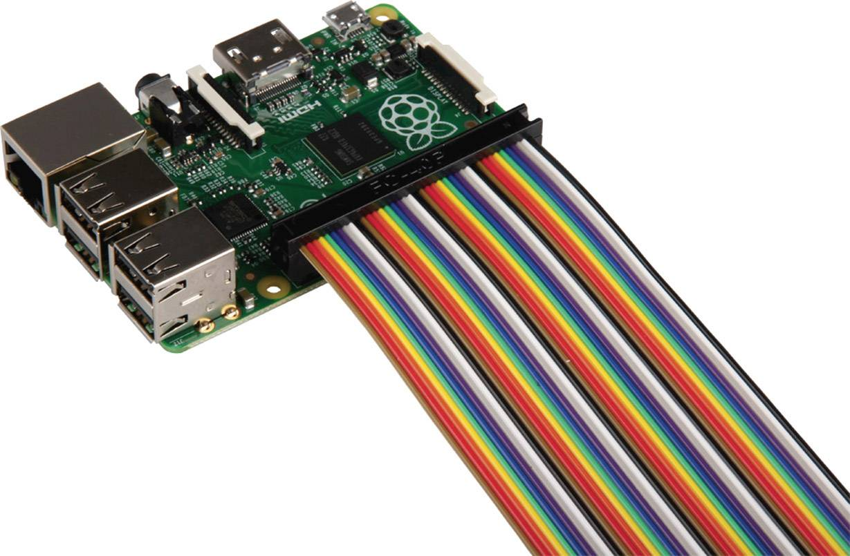
You will probably need a breadboard to make connections easier. In general, I will not suggest direct soldering on a Raspberry Pi, so it can be reused more easily. You can also use a jumper cable to extend all pins to a breadboard.
Popular GPIO libraries with Python
There are many options to program a Raspberry Pi with physical computing components, including Scratch, Bash, Node.js, C etc. We will focus on Python here. Below are two codes using two different libraries but doing the exact same thing.
1. gpiozero
The main thing to remember about gpiozero library is that it focuses on buttons and LED instead of the actual GPIO pins. i.e. LED = OUTPUT, button = INPUT. Some people may find the syntax easier to understand, like turning on the LED is literally leds.on(). gpiozero is simple and quick and it's a great place to start experimenting as a beginner. But if you are not actually using LEDs or buttons, it can be a bit confusing and it is not very compatible to merge with codes from other libraries as well. Find its documentation here.
# example of programming Raspberry Pi GPIO with gpiozero
# refer to gpiozero.readthedocs.io

import gpiozero as gpzero
from time import sleep

# set up pushbutton and bank of leds
resetbutton = gpzero.Button(3)
leds = gpzero.LEDBoard(26,16,20,21)

# functions to control behavior
def LightsOn ():
    while resetbutton.is_pressed:
        leds.on()

def ResetCounter ():
    global counter
    leds.off()
    counter = 0

def binary2lights(showThis):
    leds.value = (
        showThis & 0b1000,
        showThis & 0b0100,
        showThis & 0b0010,
        showThis & 0b0001)

# setup button handlers
resetbutton.when_pressed = LightsOn
resetbutton.when_released = ResetCounter

# send 0...15 to lights
while True:
    ResetCounter()
    while counter < 16:
        binary2lights(counter)
        counter += 1
        sleep(1)
2. RPi.GPIO
Borken Library!This library is currently not usable for Raspberry Pi 5. If you are using Pi 4 or older, it will be fine.
RPi.GPIO is a code library that allows Python to communicate with the GPIO. It is widely used and supported. In fact, gpiozero is developed based on RPi.GPIO. I find this library closer to C++ in Arduino IDE. For example, instead of on() and off(), it uses HIGH and LOW. Find its documentation here.
# example of programming Raspberry Pi GPIO with rpi.gpio
# refer to sourceforge.net/p/raspberry-gpio-python/wiki/Home

import RPi.GPIO as GPIO
from time import sleep

GPIO.setmode(GPIO.BCM) # declare BCM numbering scheme (vs GPIO.BOARD)

# set up pushbutton and bank of leds
resetbutton = 3
leds = [26, 16, 20, 21]
GPIO.setup(3, GPIO.IN)
GPIO.setup(leds, GPIO.OUT)

# function to handle reset button
def handleReset ():
    while not GPIO.input(resetbutton):
        GPIO.output(leds, GPIO.HIGH)
        print("waiting for button")
    resetLightsandCounter()


def resetLightsandCounter():
    global counter
    GPIO.output(leds, GPIO.LOW)
    counter = 0
    print("reset")


# setup button handlers
GPIO.add_event_detect(resetbutton, GPIO.FALLING)

# send 0...15 to lights
while True:
    resetLightsandCounter()
    while counter < 16:
        if GPIO.event_detected(resetbutton):
            handleReset()
        GPIO.output(leds, (
            GPIO.HIGH if counter & 0b1000 else GPIO.LOW,
            GPIO.HIGH if counter & 0b0100 else GPIO.LOW,
            GPIO.HIGH if counter & 0b0010 else GPIO.LOW,
            GPIO.HIGH if counter & 0b0001 else GPIO.LOW
        )
    )
        counter += 1
        sleep(1)