Using L293D IC for motors
What is L293D?
The L293D is a 16-pin Motor Driver IC which can control a set of two DC motors simultaneously in any direction. The L293D is designed to provide bidirectional drive currents of up to 600 mA (per channel) at voltages from 4.5 V to 36 V. It can be extremely hot. When they get overheated, they may not follow commands anymore.
It is cheap but may not have the easiest pinout to read for beginners.
DC motor
DC motor is very common to be found in toys. It usually comes with 2 wires, one red(+) and one black(-).
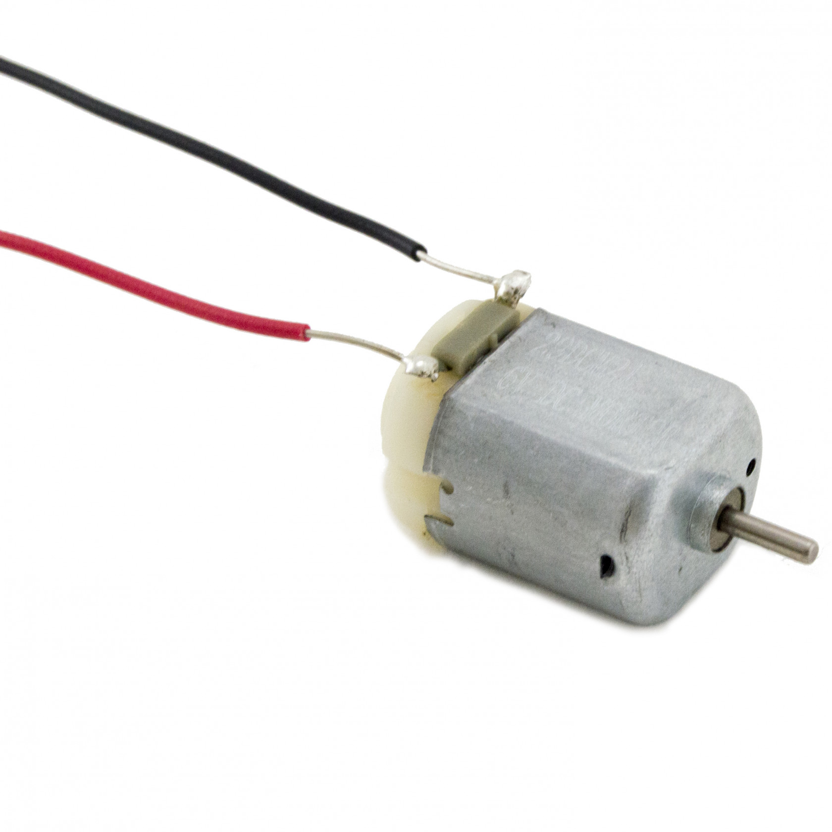
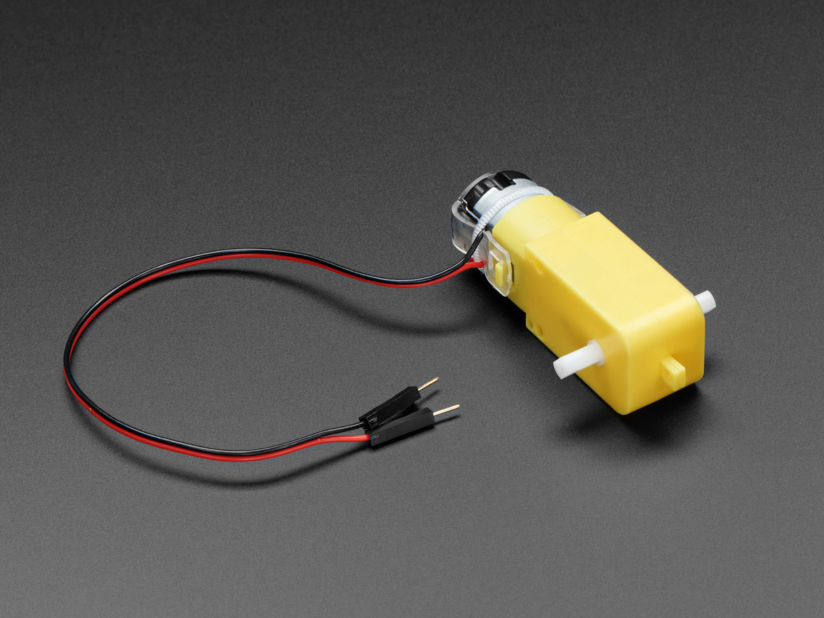
Although it can be small and cheap, it can be very fast. Therefore sometimes it comes with a gearbox which will slow down the speed of the motor.
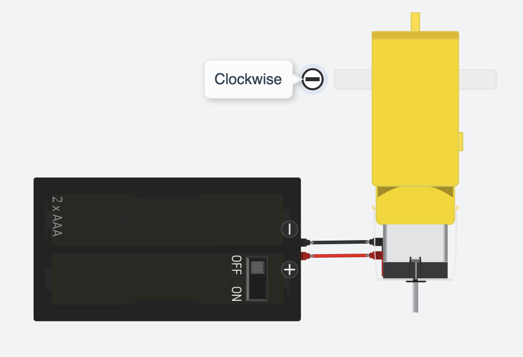
Taking a 12V DC motor for example, we connect the red wire of the motor to the positive wire of the power supply and the black wire of the motor to the negative wire of the power supply as normal practice. We will get a motor running clockwise at full speed.
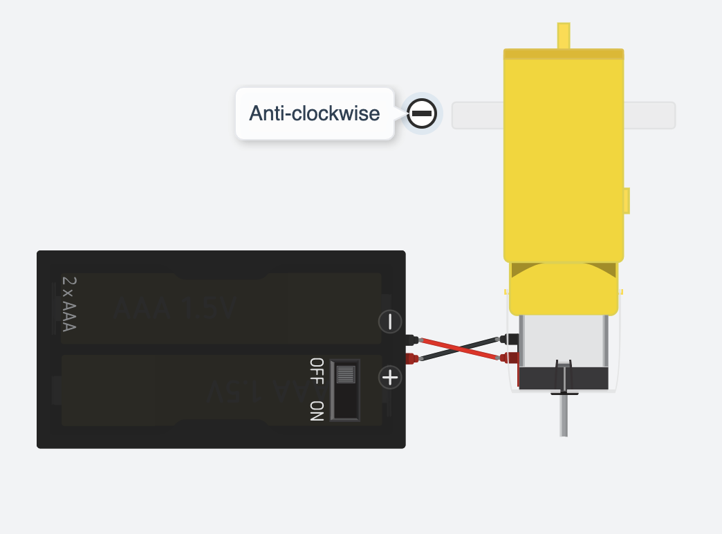
BUT if we reverse the red and black wires of the motor we connect the black wire of the motor to the positive wire of the power supply and the red wire of the motor to the negative wire of the power supply. We will get a motor running anti-clockwise at full speed.
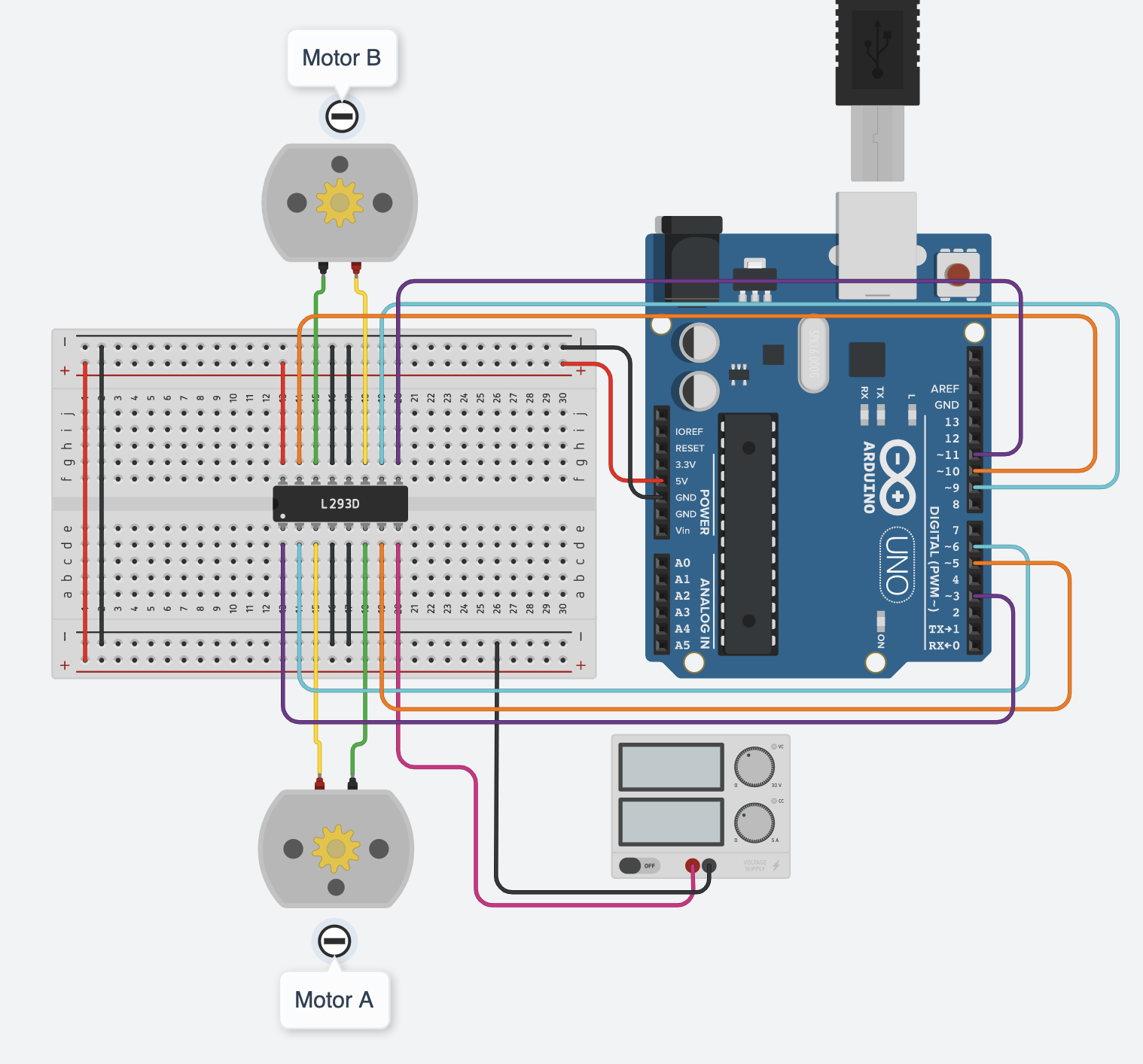
Wiring
Be careful with which pin on the IC to which pin on the Arduino as there are 16 pins you need to connect!
Pinout of L293D
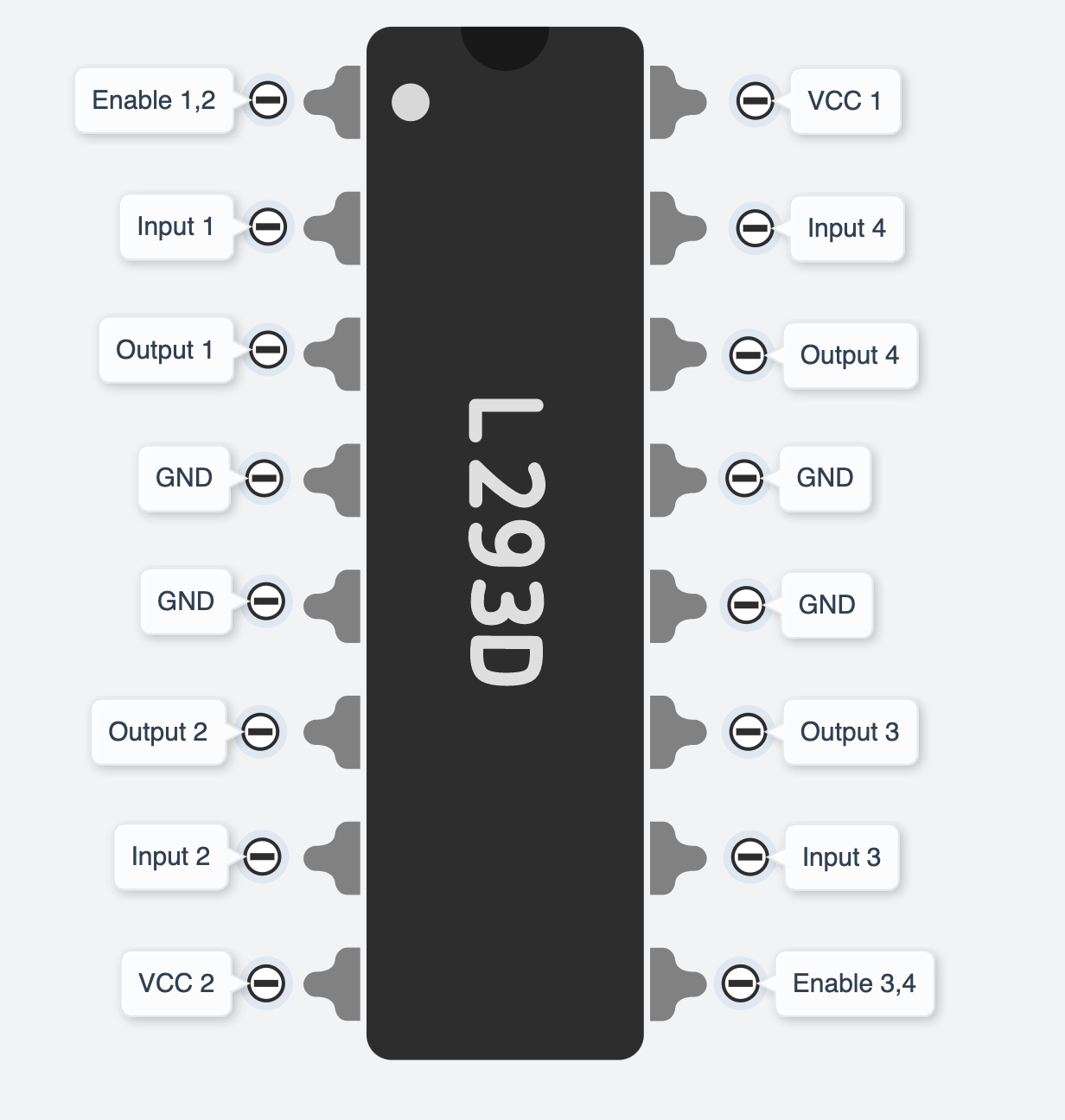
You may not understand what these labels stand for. Let's look at the below one, you can see where they are actually connected to and what they do.
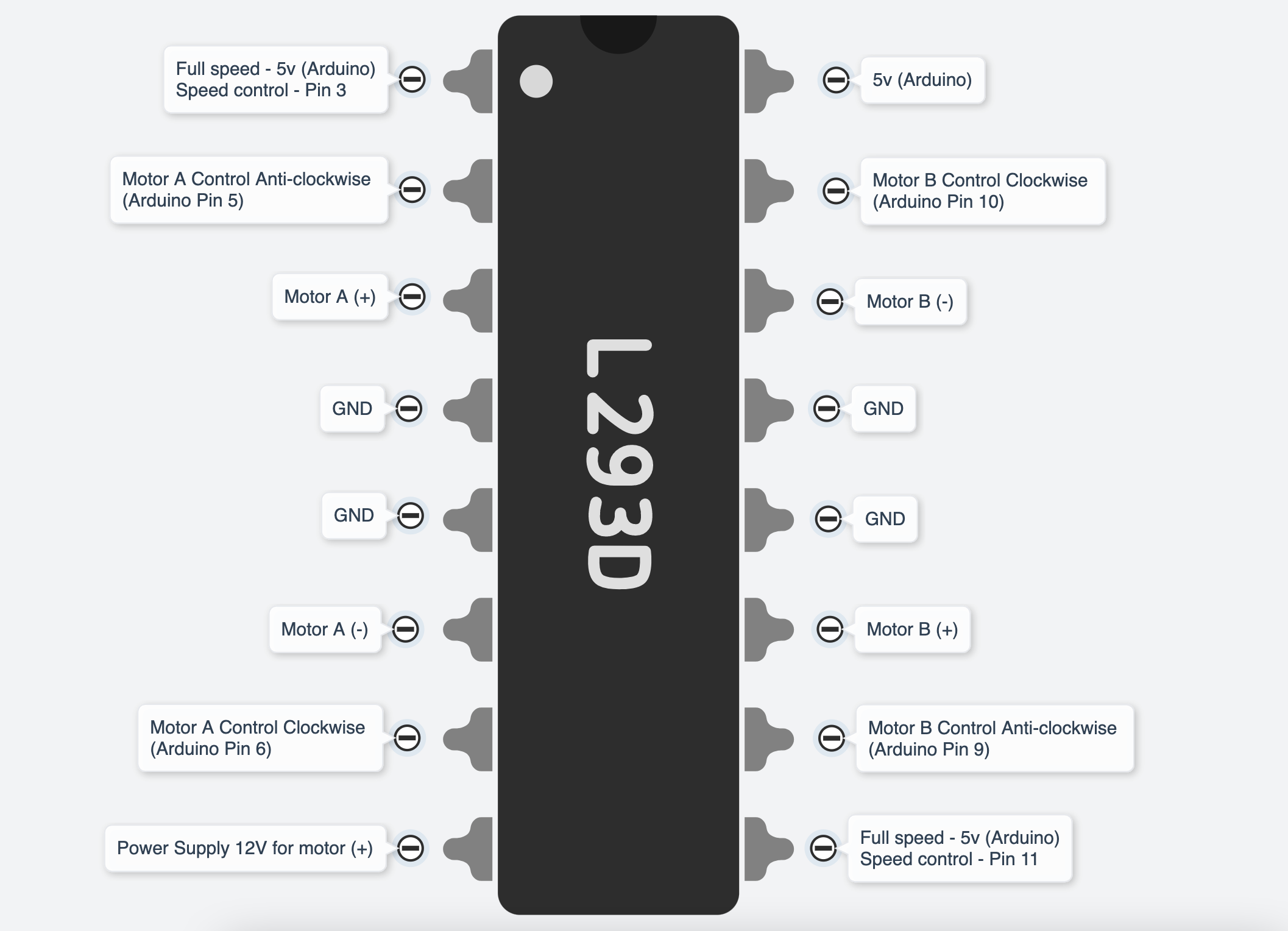
As said earlier, the DC motor changes direction by reversing the + wire and - wire. If you reverse Motor A (+) (Pin3 of IC) and Motor A (-)(Pin6 of IC), the Pin2 of IC (Arduino Pin 5) will be the Clockwise control and the Pin7 of IC (Arduino Pin 6) will be the Anti-clockwise control.
You do not have to strictly follow which digital pins on Arduino to be used, as long as you match the number of pins in the code. And you will need to use PWM(~) pins for both speed control pins on the IC (IC pin1 & 9).
Get started
This example code will let you test the directions of the motors and has custom functions for forward(), backward(), stop(), turnRight() and turnLeft().
//L293D
//Motor A
const int motorAspeed  = 3;
const int motorPin1  = 5;  // Pin 14 of L293
const int motorPin2  = 6;  // Pin 10 of L293
//Motor B
const int motorBspeed  = 11;
const int motorPin3  = 10; // Pin  7 of L293
const int motorPin4  = 9;  // Pin  2 of L293

//This will run only one time.
void setup(){

    //Set pins as outputs
    pinMode(motorPin1, OUTPUT);
    pinMode(motorPin2, OUTPUT);
    pinMode(motorPin3, OUTPUT);
    pinMode(motorPin4, OUTPUT);
    pinMode(motorAspeed, OUTPUT);
    pinMode(motorBspeed, OUTPUT);


    analogWrite(motorAspeed, 255); //set motor A speed 0-255
    analogWrite(motorBspeed, 255); //set motor B speed 0-255
  /*
    //Motor Control Testing - Motor A: motorPin1,motorpin2 & Motor B: motorpin3,motorpin4
    //This code  will turn Motor A clockwise for 2 sec.
    digitalWrite(motorPin1, HIGH); //5
    digitalWrite(motorPin2, LOW);
    digitalWrite(motorPin3, LOW);
    digitalWrite(motorPin4, LOW);
    delay(2000);
    //This code will turn Motor A counter-clockwise for 2 sec.
    digitalWrite(motorPin1, LOW);
    digitalWrite(motorPin2, HIGH); //6
    digitalWrite(motorPin3, LOW);
    digitalWrite(motorPin4, LOW);
    delay(2000);

    //This code will turn Motor B clockwise for 2 sec.
    digitalWrite(motorPin1, LOW);
    digitalWrite(motorPin2, LOW);
    digitalWrite(motorPin3, HIGH); //10
    digitalWrite(motorPin4, LOW);
    delay(2000);

    //This code will turn Motor B counter-clockwise for 2 sec.
    digitalWrite(motorPin1, LOW);
    digitalWrite(motorPin2, LOW);
    digitalWrite(motorPin3, LOW);
    digitalWrite(motorPin4, HIGH); //9
    delay(2000);

    //And this code will stop motors
    digitalWrite(motorPin1, LOW);
    digitalWrite(motorPin2, LOW);
    digitalWrite(motorPin3, LOW);
    digitalWrite(motorPin4, LOW);
  */
}


void loop(){

  forward();
  delay(5000);

  backward();
  delay(5000);

  stop();
  delay(5000);

  turnRight();
  delay(5000);

  turnLeft();
  delay(5000);
}

void forward(){
  digitalWrite(motorPin1, HIGH);
  digitalWrite(motorPin2, LOW);
  digitalWrite(motorPin3, HIGH);
  digitalWrite(motorPin4, LOW);
}


void backward(){
  digitalWrite(motorPin1, LOW);
  digitalWrite(motorPin2, HIGH);
  digitalWrite(motorPin3, LOW);
  digitalWrite(motorPin4, HIGH);
}

void stop(){
  digitalWrite(motorPin1, LOW);
  digitalWrite(motorPin2, LOW);
  digitalWrite(motorPin3, LOW);
  digitalWrite(motorPin4, LOW);
}

void turnRight(){
  digitalWrite(motorPin1, HIGH);
  digitalWrite(motorPin2, LOW);
  digitalWrite(motorPin3, LOW);
  digitalWrite(motorPin4, LOW);
}

void turnLeft(){
  digitalWrite(motorPin1, LOW);
  digitalWrite(motorPin2, LOW);
  digitalWrite(motorPin3, HIGH);
  digitalWrite(motorPin4, LOW);
}
There is a simulated circuit made in Tinkercad for you to try out!